EP1559651A2 - Verpackungsmaschine, insbesondere für Blumentöpfe - Google Patents
Verpackungsmaschine, insbesondere für Blumentöpfe Download PDFInfo
- Publication number
- EP1559651A2 EP1559651A2 EP04028321A EP04028321A EP1559651A2 EP 1559651 A2 EP1559651 A2 EP 1559651A2 EP 04028321 A EP04028321 A EP 04028321A EP 04028321 A EP04028321 A EP 04028321A EP 1559651 A2 EP1559651 A2 EP 1559651A2
- Authority
- EP
- European Patent Office
- Prior art keywords
- machine according
- drawplate
- sheet
- product
- worktop
- Prior art date
- Legal status (The legal status is an assumption and is not a legal conclusion. Google has not performed a legal analysis and makes no representation as to the accuracy of the status listed.)
- Withdrawn
Links
- 238000004806 packaging method and process Methods 0.000 title claims abstract description 15
- 239000000463 material Substances 0.000 claims abstract description 24
- 239000000853 adhesive Substances 0.000 claims abstract description 20
- 230000001070 adhesive effect Effects 0.000 claims abstract description 20
- 230000001681 protective effect Effects 0.000 claims abstract description 7
- 238000003860 storage Methods 0.000 claims description 10
- 239000012528 membrane Substances 0.000 claims description 4
- 239000007921 spray Substances 0.000 claims description 4
- 238000005520 cutting process Methods 0.000 claims description 3
- 230000010355 oscillation Effects 0.000 claims description 3
- 239000003292 glue Substances 0.000 claims description 2
- 239000012943 hotmelt Substances 0.000 claims description 2
- 241000252254 Catostomidae Species 0.000 claims 1
- 239000004033 plastic Substances 0.000 description 3
- 229920003023 plastic Polymers 0.000 description 3
- 230000000670 limiting effect Effects 0.000 description 2
- 238000000034 method Methods 0.000 description 2
- 230000000007 visual effect Effects 0.000 description 2
- 238000004026 adhesive bonding Methods 0.000 description 1
- 230000005540 biological transmission Effects 0.000 description 1
- 239000004927 clay Substances 0.000 description 1
- 230000006835 compression Effects 0.000 description 1
- 238000007906 compression Methods 0.000 description 1
- 238000004519 manufacturing process Methods 0.000 description 1
- 238000012986 modification Methods 0.000 description 1
- 230000004048 modification Effects 0.000 description 1
- 238000007493 shaping process Methods 0.000 description 1
Images


Classifications
-
- B—PERFORMING OPERATIONS; TRANSPORTING
- B65—CONVEYING; PACKING; STORING; HANDLING THIN OR FILAMENTARY MATERIAL
- B65B—MACHINES, APPARATUS OR DEVICES FOR, OR METHODS OF, PACKAGING ARTICLES OR MATERIALS; UNPACKING
- B65B51/00—Devices for, or methods of, sealing or securing package folds or closures; Devices for gathering or twisting wrappers, or necks of bags
- B65B51/02—Applying adhesives or sealing liquids
- B65B51/026—Applying adhesives or sealing liquids using rotating applicators
-
- B—PERFORMING OPERATIONS; TRANSPORTING
- B65—CONVEYING; PACKING; STORING; HANDLING THIN OR FILAMENTARY MATERIAL
- B65B—MACHINES, APPARATUS OR DEVICES FOR, OR METHODS OF, PACKAGING ARTICLES OR MATERIALS; UNPACKING
- B65B11/00—Wrapping, e.g. partially or wholly enclosing, articles or quantities of material, in strips, sheets or blanks, of flexible material
- B65B11/54—Wrapping by causing the wrapper to embrace one end and all sides of the contents, and closing the wrapper onto the opposite end by forming regular or irregular pleats
-
- B—PERFORMING OPERATIONS; TRANSPORTING
- B65—CONVEYING; PACKING; STORING; HANDLING THIN OR FILAMENTARY MATERIAL
- B65B—MACHINES, APPARATUS OR DEVICES FOR, OR METHODS OF, PACKAGING ARTICLES OR MATERIALS; UNPACKING
- B65B25/00—Packaging other articles presenting special problems
- B65B25/02—Packaging agricultural or horticultural products
- B65B25/026—Packaging flower pots
-
- B—PERFORMING OPERATIONS; TRANSPORTING
- B65—CONVEYING; PACKING; STORING; HANDLING THIN OR FILAMENTARY MATERIAL
- B65B—MACHINES, APPARATUS OR DEVICES FOR, OR METHODS OF, PACKAGING ARTICLES OR MATERIALS; UNPACKING
- B65B41/00—Supplying or feeding container-forming sheets or wrapping material
- B65B41/02—Feeding sheets or wrapper blanks
- B65B41/04—Feeding sheets or wrapper blanks by grippers
- B65B41/06—Feeding sheets or wrapper blanks by grippers by suction-operated grippers
Definitions
- the present invention relates to a machine for packaging products, particularly flowerpots.
- the package allows to facilitate the application of any adhesive labels or the like that bear bar codes or any other information related to the plants, which are unlikely to adhere firmly to the uneven and sometimes dirty surfaces of pots.
- These packages can be constituted for example by paper boxes, which are assembled on the pot so as to accommodate it inside them and from which the plant protrudes.
- Another type of package that is widely used as an alternative to the preceding one consists of a decorative sheet, which is closed around the pot and fixed to it by means of ribbons, laces, elastic bands or straps.
- Said sheet can be made for example of paper, plastics or other material or can be of the so-called multi-ply type, i.e., constituted by two superimposed layers of different materials that adhere to each other.
- the ribbon surrounds the decorative sheet above the rim of the pot to be packaged so as to avoid accidental opening of the resulting package.
- the central portion of the sheet is therefore arranged in contact with the pot while its perimetric band assumes a pleasant undulated shape and surrounds the plant contained in the pot.
- the placement of the pot on the sheet and the subsequent shaping of the sheet closed around said pot are in fact performed differently, obtaining in each instance more or less pleasant packages.
- the placement of the ribbon above the rim of the pot to be packaged entails the need to use large sheets in order to obtain a pleasant visual effect of the resulting package.
- the aim of the present invention is to eliminate the above-mentioned drawbacks of known packages, by providing a machine for packaging products, particularly flowerpots, that allows to reduce significantly the processing times and costs and uses rather low-cost materials.
- an object of the present invention is to obtain packages whose shape is as similar as possible and whose aesthetic value is constant over time.
- Another object of the present invention is to facilitate the application of any adhesive labels or the like and to ensure their durable adhesion.
- Another object of the present invention is to reduce significantly the consumption of material used to obtain the packages without however penalizing their aesthetic value.
- Another object of the present invention is to provide a machine that is simple, relatively easy to provide in practice, safe in use, effective in operation, and has a relatively low cost.
- the present machine for packaging products which comprises a frame for supporting a worktop that comprises at least one drawplate for the passage of a corresponding product to be packaged, means for feeding at least one decorative and/or protective sheet for packaging said product on said worktop at said drawplate, and means for releasing said product onto said sheet at said drawplate, adhesion means being associated with said sheet and with said product and being suitable to keep them in mutual contact following passage through said drawplate, characterized in that it comprises presser means, which are suitable to force the passage of said product and of said sheet through said drawplate and in that said adhesion means comprise at least one layer of adhesive material that is interposed between said product and said sheet.
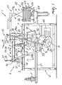
- the reference numeral 1 generally designates a machine for packaging products, particularly flowerpots.
- the machine 1 is suitable in particular to package flowerpots V which contain the corresponding plants, which are preferably small- and medium-sized.
- the machine 1 comprises a frame 2 for supporting a horizontal worktop 3, which comprises at least one drawplate 4 for the passage of a pot V to be packaged, means 5 for feeding a decorative and/or protective sheet F for packaging said pot on the worktop 3 at the drawplate 4, and means 6 for releasing a pot V onto the sheet F at said drawplate.
- Adhesion means are provided which are associated with the sheet F and with the pot V and are suitable to keep them in mutual contact following passage through the drawplate 4.
- said adhesion means comprise at least one layer of adhesive material M, which is interposed between the sheet F and the pot V and is preferably applied to the upper face of the sheet F.
- such layer may be applied externally to the pot V or both to the pot and to the sheet F.
- the sheet F is of the type traditionally used in the packaging of plants and can be constituted for example by paper, plastics, or other material, or can be of the so-called multi-ply type.
- it can be quadrangular or circular and can have a smooth or corrugated perimetric edge.
- the sheet F is arranged by the feeder means 5 so that the drawplate 4 is located at its central region.
- the sheet F In passing through the drawplate 4, the sheet F is folded onto the pot V and its central portion is arranged so that it adheres to the outer surface of the pot, while the perimetric portion of the sheet F is left protruding above the pot V so as to surround the plant contained therein.
- the layer of adhesive material M maintains the adhesion of the sheet F to the pot V after passage through the drawplate 4.
- the drawplate 4 is constituted by a substantially elastic membrane, which is provided with an opening 7 for the passage of the pot V, together with the corresponding sheet F, and is accommodated at a receptacle 8 formed on the worktop 3.
- the membrane is preferably provided with a plurality of radial notches 9 distributed along the opening 7.
- the machine 1 comprises presser means 10, which are suitable to force the passage of the pot V and of the sheet F through the drawplate 4.
- the machine 1 is provided with means 11 for gripping and removing the packaged pot V' from the drawplate 4, which are arranged below the worktop 3 proximate to the drawplate.
- the release means 6 comprise a first automatic and preferably self-centering clamp 12, which is supported by the frame 2 above the worktop 3 and can slide along a sliding direction S that is parallel to said worktop between a configuration for gripping the pot V and a configuration for releasing it at the drawplate 4, and first means 13 for actuating the sliding of the first clamp.
- the first clamp 12 may be for example of the pneumatic type.
- the release means 6 comprise a first continuous conveyor 14, such as for example a conventional conveyor belt, for feeding a plurality of pots V, which is arranged transversely to the direction S and so that its unloading side is arranged in a lower region proximate to the first clamp 12 in the grip configuration.
- a first continuous conveyor 14 such as for example a conventional conveyor belt
- the first conveyor 14 is arranged above the worktop 3.
- the presser means 10 comprise an oscillating lever 15, which is supported by the frame 2 above the drawplate 4, and second means 16 for actuating the oscillation of the lever.
- the oscillating lever 15 is pivoted proximate to the centerline to the frame 2, and its second end, which lies opposite the first end, is associated with the second actuation means 16.
- the grip and removal means 11 comprise a second automatic clamp 17, which is preferably self-centering, is supported by the frame 2 below the drawplate 4, and can slide in a vertical direction between a configuration for gripping the pot V' from the drawplate and a configuration for releasing the pot, and third means 18 for actuating the sliding of the second clamp 17.
- a second automatic clamp 17 which is preferably self-centering, is supported by the frame 2 below the drawplate 4, and can slide in a vertical direction between a configuration for gripping the pot V' from the drawplate and a configuration for releasing the pot, and third means 18 for actuating the sliding of the second clamp 17.
- the second clamp 17 may be for example of the pneumatic type.
- the frame 2 is provided with at least two profiled elements 19, which are arranged vertically and along which a sliding block 20 is slidingly associated, the sliding block supporting the second clamp 17 in a cantilever manner.
- the grip and removal means 11 have a second continuous conveyor 21, for transferring the pots V', which is arranged so that its loading side is in a lower region proximate to the second clamp 17 in the release configuration.
- the second conveyor 21 is constituted for example by a conventional conveyor belt.
- the second clamp 17 unloads the pots V' onto the second conveyor 21.
- the machine 1 comprises a unit 22 for storing a plurality of sheets F, the feeder means 5 being suitable to individually separate said sheets and pick them up one at a time.
- the storage unit 22 comprises a stack 23 of sheets F, which is arranged proximate to the worktop 3, and preferably comprises pusher means 24, which are suitable to keep the sheet F that is arranged at the top of said stack at a level that is proximate to the level of the worktop 3.
- the pusher means 24 are constituted for example by a fluid-operated actuator, which is supported by the frame 2 below the stack 23 and in which the piston presses from below against a pan 25 for supporting the stack, which is accommodated between a plurality of containment guides 26 that protrude vertically from the frame 2.
- the storage unit 22 might provide, for example, a reel for feeding a continuous strip of decorative and/or protective material, strip cutting means being interposed between the storage unit 22 and the drawplate 4 in order to obtain sheets F, having a suitable geometry and dimensions, to be fed toward said drawplate.
- the machine 1 comprises means 27 for applying the layer of adhesive material M, which are suitable to spread the layer on a portion 28 of the upward face of the sheet F arranged at the top of the stack.
- the portion 28 is constituted by a ring, which is arranged at the central portion of the sheet F which, in passing through the drawplate 4, is arranged so as to adhere to the pot V at its upper rim.
- the diameter of the ring is variable according to the dimensions of the pot V.
- the perimetric band of the sheet F in fact opens with an undulated shape directly above the rim of the pot V, without forming the narrower region that inevitably occurs at the ribbon that is used traditionally.
- the application means 27 may have, for example, a conventional spray dispenser 27a, which is arranged above the stack 23 and is associated with means for feeding the adhesive material M, which are not shown since they are of a known type.
- the application means 27 can be arranged directly on the worktop 3.
- the feeder means 5 comprise at least one grip element 29, which is supported by the frame 2 above the worktop 3 and can move along the direction S, and fourth means 30 for actuating the sliding of said element.
- the grip element 29 is preferably of the sucker or clamp type or the like.
- the machine 1 may be provided with means for applying an adhesive label E or the like to the sheet F taken from the stack 23, such means not being shown in the figures and being arranged below the worktop 3.
- the label E may have, for example, a bar code or any type of information related to the type of plant contained in the corresponding pot V.
- the label E is thus applied below the central portion of the sheet F, designed to be arranged at the bottom of the pot V, so as to facilitate its adhesion and subsequent reading for example by means of bar code readers.
- the feeder means 5 comprise two grip elements 29, which are mutually spaced and can move simultaneously along the direction S; one of said grip elements, designated by the reference numeral 29a, is suitable to take the first sheet F from the stack 23 and carry it to the applicator means, and the other grip element, designated by the reference numeral 29b, is suitable to transfer the previously taken sheet F, with the label E already applied thereto, from the applicator means to the drawplate 4.
- the applicator means are arranged in an intermediate position between the stack 23 and the drawplate 4 and at a distance from them that is on the same order of magnitude as the gap between the two grip elements 29.
- the two grip elements 29 might have respective fourth mutually independent actuation means 30.
- the first, second, third and fourth actuation means may be for example of the fluid-operated (pneumatic or hydraulic) type, of the mechanical type, or of the electromechanical type.
- each one can be provided with a respective rotating cam for actuating a corresponding lever system.
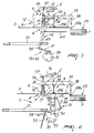
- first actuation means 13 and the fourth actuation means 30 are mutually integrated ( Figure 3) and comprise a first rotating cam 31, which is associated with a first lever system 32 for actuating the alternating sliding, along the direction S, of a carriage 33 that supports the first clamp 12 and the grip elements 29.
- the carriage 33 is arranged above the worktop 3 along the direction S and rests slidingly on a plurality of supporting wheels 34, which are freely associated with the frame 2.
- the first clamp 12 is associated with a vertical bar 35, which is inserted slidingly within a sleeve 36 that is rigidly coupled to the carriage 33, by interposing an elastic compression spring, not shown in the figures, which is pre-adjusted so as to keep the level of the first clamp fixed during sliding in the direction S.
- the downward thrust applied by the presser means 10 is such as to contrast the reaction of said spring, so as to allow the downward translational motion of the first clamp 12 in the release configuration.
- the rod 35 is associated in an upper region with a free wheel 37, on which the oscillating lever 15 rests when the first clamp 12 is in the release configuration.
- the grip elements 29 are also associated, so that they can move in a vertical direction, with the carriage 33 by interposing respective actuators 38.
- the first cam 31 is keyed to a rotating shaft 39 that is associated with a motor 40.
- the first lever system 32 is constituted by a first lever 41, which has an end that acts as a tappet and rests on the first cam 31, by a linkage 42, which is pivoted to the sleeve 36, and by a second lever 43, which is interposed between the preceding ones.
- the first lever 41 and the second lever 43 are mutually connected so as to form a single substantially L-shaped body.
- first elastic traction spring 44 which is interposed between the second lever 43 and the frame 2 and keeps the end of the first lever 41 in contact with the first cam 31.
- Figure 3 shows in solid lines the carriage 33, which is arranged so as to place the first clamp 12 at the release configuration, and shows in dashed lines the carriage in a position that is intermediate between the two end configurations.
- the second actuation means 16 ( Figure 5) comprise a second rotating cam 45, which is also keyed to the shaft 39 and is associated with a second lever system 46 for actuating the oscillation of the oscillating lever 15.
- the second lever system 46 is constituted by a third lever 47, which has an end that rests on the second cam 44 and acts as a tappet, and by a fourth lever 48, whose opposite ends are pivoted respectively along the third lever 47 and to the second end of the oscillating lever 15.
- the second lever system 46 is associated with a second elastic traction spring 49, which is interposed between the third lever 47 and the frame 2 and keeps the end of the third lever in contact with the second cam 45.
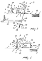
- Figure 5 illustrates the machine 1 with the first clamp 12 in the grip configuration and the oscillating lever 15 in the raised position
- Figure 6 illustrates the machine 1 with the first clamp 12 in the release configuration and the oscillating lever 15 in the lowered position.
- the third actuation means 18 ( Figure 4) comprise a third cam 50, which is also keyed on the shaft 39 and is associated with a third lever system 51 for actuating the alternating sliding in a vertical direction of the second clamp 17.
- the third lever system 51 is constituted by a fifth lever 52, which acts as a tappet and is kept tangent to the third cam 50 by means of a third elastic traction spring 53, which is interposed between the fifth lever and the frame 2, and by a sixth lever 54, the opposite ends of which are pivoted respectively to the fifth lever 52 and to the sliding block 20.
- the first lever system 32, the second lever system 46 and the third lever system 51 are interconnected, since the first lever 41, the third lever 47 and the fifth lever 52 are assembled so that they can rotate about a common pivot 55.
- the first cam 31, the second cam 45 and the third cam 50 are shaped so as to have appropriate profiles that provide the motion that one wishes to impart to the corresponding transmission elements.
- the applicator means 27 comprise at least one device 56 for dispensing the adhesive material M, such as a hot-melt glue gun, a spray dispenser or the like, which is fed by means of a flexible hose 56 and is supported in an upper region proximate to the stack 23 by a unit 58 for actuation along a substantially circular path that lies on a plane that is substantially parallel to the plane of arrangement of the sheets F arranged in the stack 23 and is therefore horizontal.
- a device 56 for dispensing the adhesive material M such as a hot-melt glue gun, a spray dispenser or the like, which is fed by means of a flexible hose 56 and is supported in an upper region proximate to the stack 23 by a unit 58 for actuation along a substantially circular path that lies on a plane that is substantially parallel to the plane of arrangement of the sheets F arranged in the stack 23 and is therefore horizontal.
- the actuation unit 58 comprises a shaft 59, which is actuated so as to rotate about an axis R, which is substantially perpendicular to the plane of arrangement of the sheets F in the stack 23 and is therefore vertical, by a gearmotor 60, which is supported by the frame 2; a pivot 61, which is associated with the shaft 59 and is arranged transversely thereto; a first ball joint 62, which is associated with an end of the pivot 61 and is interposed between said pivot and a first end of a bar 63 whose longitudinal axis A is inclined with respect to the axis R and is incident thereto, and supports at the second end, which is arranged opposite the first end, the dispensing device 56; and a second ball joint 64, which is supported by the frame 2 and is interposed between the frame and the bar 63 at a region where the axes R and A intersect.
- the dispenser 56 is provided with at least one outlet 56a for the outflow of the adhesive material, which is arranged proximate to the longitudinal axis A and is preferably arranged thereon.
- the actuation unit 58 is provided with means 65 for adjusting the angular position of the bar 63 with respect to the shaft 59, which comprise for example conventional screw means, not shown in detail, for stopping the pivot 61 that is inserted so as to pass through said shaft.
- operation is as follows: the first clamp 12, initially in the release configuration, moves toward the grip configuration; during the corresponding stroke of the carriage 33, the grip elements 29 entrain the corresponding sheets F, so that the grip element 29b feeds the corresponding sheet F at the drawplate 4.
- the applicator means 27 have applied beforehand a layer of adhesive material M to the sheet F taken by the grip element 29a from the stack 23.
- the first clamp 12 in the grip configuration takes a pot V from the first conveyor 14 and the carriage 33 thus begins the return stroke toward the release configuration; in this step, the grip elements 29a and 29b, which have already released the corresponding sheets F respectively at the applicator means and at the drawplate 4, are inactive.
- the carriage 33 begins to perform a translational motion along the direction S so as to move the first clamp 12 to the release configuration, while the applicator means 27 dispense a preset amount of adhesive material M onto the new first sheet F of the stack 23.
- the presser means 10 produce the translational motion of the first clamp 12 toward the drawplate 4, on which a sheet F is already arranged.
- the pot V with the corresponding sheet F interposed, is then pushed through the drawplate 4 so as to arrange said sheet so that it adheres to the outer surface of the pot V.
- the first clamp 12 releases the pot V; the lower portion of said pot, which protrudes below the worktop 3, is gripped, together with the covering sheet F, by the second clamp 17 arranged in the grip configuration.
- the portion 28 of the sheet F is arranged so as to adhere to the pot V, ensuring its adhesive bonding.
- the third actuation means 18 produce the downward translational motion of the second clamp 17, which once it has reached the release configuration unloads the packaged pot V' onto the second conveyor 21.
- the described invention achieves the proposed aim and objects and in particular the object of automating and thus improving the speed and reducing the cost of the process for packaging flowerpots.
Landscapes
- Engineering & Computer Science (AREA)
- Mechanical Engineering (AREA)
- Life Sciences & Earth Sciences (AREA)
- Agronomy & Crop Science (AREA)
- Packging For Living Organisms, Food Or Medicinal Products That Are Sensitive To Environmental Conditiond (AREA)
- Making Paper Articles (AREA)
Applications Claiming Priority (2)
| Application Number | Priority Date | Filing Date | Title |
|---|---|---|---|
| ITMO20030330 ITMO20030330A1 (it) | 2003-12-04 | 2003-12-04 | Macchina per la confezione di prodotti, particolarmente vasi da fiori. |
| ITMO20030330 | 2003-12-04 |
Publications (2)
| Publication Number | Publication Date |
|---|---|
| EP1559651A2 true EP1559651A2 (de) | 2005-08-03 |
| EP1559651A3 EP1559651A3 (de) | 2005-10-26 |
Family
ID=34640381
Family Applications (1)
| Application Number | Title | Priority Date | Filing Date |
|---|---|---|---|
| EP04028321A Withdrawn EP1559651A3 (de) | 2003-12-04 | 2004-11-30 | Verpackungsmaschine, insbesondere für Blumentöpfe |
Country Status (2)
| Country | Link |
|---|---|
| EP (1) | EP1559651A3 (de) |
| IT (1) | ITMO20030330A1 (de) |
Cited By (1)
| Publication number | Priority date | Publication date | Assignee | Title |
|---|---|---|---|---|
| EP3138667A1 (de) * | 2015-09-03 | 2017-03-08 | Spisa Holding AB | Robotische vorrichtung zur umhüllung von topfpflanzen und verfahren zur umhüllung von topfpflanzen mit der robotischen umhüllungsvorrichtung |
Family Cites Families (6)
| Publication number | Priority date | Publication date | Assignee | Title |
|---|---|---|---|---|
| GB162531A (en) * | 1920-04-20 | 1921-05-05 | Forgrove Mach | Improvements in or relating to tablet-wrapping machines |
| US5450707A (en) * | 1993-07-08 | 1995-09-19 | Highland Supply Corporation | Conveyable cover former and fastening system |
| CA2099438C (en) * | 1992-09-30 | 2000-02-22 | Donald E. Weder | Article packaging system |
| GB9424616D0 (en) * | 1994-12-07 | 1995-01-25 | Harper Robert I | Wrapping method and apparatus |
| US5611192A (en) * | 1995-06-07 | 1997-03-18 | Southpac Trust International, Inc. | Apparatus for dispensing and wrapping a sheet of material about a flower pot or floral grouping |
| ITBO20000685A1 (it) * | 2000-11-23 | 2002-05-23 | Gianluigi Gamberini | Dispositivo di traino per macchine per il confezionamento di articoliin rotoli e simili |
-
2003
- 2003-12-04 IT ITMO20030330 patent/ITMO20030330A1/it unknown
-
2004
- 2004-11-30 EP EP04028321A patent/EP1559651A3/de not_active Withdrawn
Cited By (1)
| Publication number | Priority date | Publication date | Assignee | Title |
|---|---|---|---|---|
| EP3138667A1 (de) * | 2015-09-03 | 2017-03-08 | Spisa Holding AB | Robotische vorrichtung zur umhüllung von topfpflanzen und verfahren zur umhüllung von topfpflanzen mit der robotischen umhüllungsvorrichtung |
Also Published As
| Publication number | Publication date |
|---|---|
| ITMO20030330A1 (it) | 2005-06-05 |
| EP1559651A3 (de) | 2005-10-26 |
Similar Documents
| Publication | Publication Date | Title |
|---|---|---|
| AU618353B2 (en) | Straight through labelling machine | |
| US5188696A (en) | Wrap around labeling machine | |
| RU2623986C2 (ru) | Устройство и способ нанесения этикетки на коробку | |
| IE47986B1 (en) | Improvements in and relating to the attachment of tubes to packaging containers | |
| US20010022065A1 (en) | Device for packaging products in containers sealed with stretchable plastic film | |
| JP4387853B2 (ja) | 取っ手を取り付けるための装置 | |
| US4767390A (en) | Apparatus for and method of applying handle to carton closure flap | |
| US3279146A (en) | Machine for banding counted stacks of flat, sheet-like objects | |
| US5389190A (en) | Apparatus and method for applying a twist-tie to a packaging container | |
| US6066223A (en) | Labeling machine and method | |
| US5657855A (en) | Indicia applicator for cigarette packages | |
| US4002003A (en) | Method for securing articles to a display board | |
| EP0057144A2 (de) | Maschine zum Verpacken von zylinderförmigen Artikeln in kreisförmigen Zuschnitten, geformt aus Bahnen von thermoplastischem Verpackungsmaterial | |
| IL32403A (en) | Carton closing and labelling method and apparatus | |
| US3885373A (en) | Apparatus for securing articles to a display board | |
| EP0792235B1 (de) | Verfahren und vorrichtung zum einwickeln von kugelförmigen gegenständen | |
| US2815626A (en) | Banding machine | |
| US2910205A (en) | Method and machine for taping | |
| CA2682280C (en) | Labeling machine | |
| JPS6229285B2 (de) | ||
| CN112644796A (zh) | 一种桶装水包装一次性封口成型机 | |
| US5468325A (en) | Process for applying an adhesive band having one adhesive side | |
| CN111673856A (zh) | 一种实木复合板点胶装置 | |
| WO2002006124A1 (en) | Machine for attaching sachets to articles | |
| JPH09505259A (ja) | 物品包装装置 |
Legal Events
| Date | Code | Title | Description |
|---|---|---|---|
| PUAI | Public reference made under article 153(3) epc to a published international application that has entered the european phase |
Free format text: ORIGINAL CODE: 0009012 |
|
| AK | Designated contracting states |
Kind code of ref document: A2 Designated state(s): AT BE BG CH CY CZ DE DK EE ES FI FR GB GR HU IE IS IT LI LU MC NL PL PT RO SE SI SK TR |
|
| AX | Request for extension of the european patent |
Extension state: AL HR LT LV MK YU |
|
| PUAL | Search report despatched |
Free format text: ORIGINAL CODE: 0009013 |
|
| AK | Designated contracting states |
Kind code of ref document: A3 Designated state(s): AT BE BG CH CY CZ DE DK EE ES FI FR GB GR HU IE IS IT LI LU MC NL PL PT RO SE SI SK TR |
|
| AX | Request for extension of the european patent |
Extension state: AL HR LT LV MK YU |
|
| 17P | Request for examination filed |
Effective date: 20060227 |
|
| AKX | Designation fees paid |
Designated state(s): AT BE BG CH CY CZ DE DK EE ES FI FR GB GR HU IE IS IT LI LU MC NL PL PT RO SE SI SK TR |
|
| 17Q | First examination report despatched |
Effective date: 20070308 |
|
| STAA | Information on the status of an ep patent application or granted ep patent |
Free format text: STATUS: THE APPLICATION IS DEEMED TO BE WITHDRAWN |
|
| 18D | Application deemed to be withdrawn |
Effective date: 20070719 |