EP1559835B1 - Dispositif et procédé pour enduire deux faces d'une bande de matériau en mouvement avec un medium fluide ou pâteux, en particulier du papier ou du carton, ainsi qu'un procédé adapté lié pour déterminer des enductions separées relatives à la surface - Google Patents
Dispositif et procédé pour enduire deux faces d'une bande de matériau en mouvement avec un medium fluide ou pâteux, en particulier du papier ou du carton, ainsi qu'un procédé adapté lié pour déterminer des enductions separées relatives à la surface Download PDFInfo
- Publication number
- EP1559835B1 EP1559835B1 EP05100081A EP05100081A EP1559835B1 EP 1559835 B1 EP1559835 B1 EP 1559835B1 EP 05100081 A EP05100081 A EP 05100081A EP 05100081 A EP05100081 A EP 05100081A EP 1559835 B1 EP1559835 B1 EP 1559835B1
- Authority
- EP
- European Patent Office
- Prior art keywords
- web
- area
- medium
- sides
- application
- Prior art date
- Legal status (The legal status is an assumption and is not a legal conclusion. Google has not performed a legal analysis and makes no representation as to the accuracy of the status listed.)
- Expired - Lifetime
Links
Images


Classifications
-
- D—TEXTILES; PAPER
- D21—PAPER-MAKING; PRODUCTION OF CELLULOSE
- D21H—PULP COMPOSITIONS; PREPARATION THEREOF NOT COVERED BY SUBCLASSES D21C OR D21D; IMPREGNATING OR COATING OF PAPER; TREATMENT OF FINISHED PAPER NOT COVERED BY CLASS B31 OR SUBCLASS D21G; PAPER NOT OTHERWISE PROVIDED FOR
- D21H23/00—Processes or apparatus for adding material to the pulp or to the paper
- D21H23/78—Controlling or regulating not limited to any particular process or apparatus
-
- D—TEXTILES; PAPER
- D21—PAPER-MAKING; PRODUCTION OF CELLULOSE
- D21H—PULP COMPOSITIONS; PREPARATION THEREOF NOT COVERED BY SUBCLASSES D21C OR D21D; IMPREGNATING OR COATING OF PAPER; TREATMENT OF FINISHED PAPER NOT COVERED BY CLASS B31 OR SUBCLASS D21G; PAPER NOT OTHERWISE PROVIDED FOR
- D21H23/00—Processes or apparatus for adding material to the pulp or to the paper
- D21H23/02—Processes or apparatus for adding material to the pulp or to the paper characterised by the manner in which substances are added
- D21H23/22—Addition to the formed paper
Definitions
- the invention relates, in one aspect, to a machine for application of a liquid or pasty application medium on both sides of a moving material web, in particular of paper or cardboard, with a sensor arrangement which responds to the total area-related application of application medium on both sides of the material web or / and at least one size dependent on the area-related total order of application medium on both sides of the material web.
- Such machines are known in many forms. It is particularly thought of so-called coating machines for the online painting or the offline coating of paper or cardboard on both sides, namely to such machines in which both sides are deleted simultaneously or quasi-simultaneously or immediately or in quick succession. It is particularly thought of such cases in which the web side has not dried before the other web page is deleted.
- the machine may be equipped with a film press coater which simultaneously applies to both sides of the web.
- coating units such as curtain applicators, spray applicators or so-called blade or blade applicators or applicators with corresponding doctor devices, which apply in each case only to one side of the material web.
- the coating weight on each side must be determined or at least taken into account when painting on both sides.
- line weight sensors that can reflectively measure the line weight for a web side according to a near-infrared absorption method.
- the total line weight that is, the sum of the individual line weights on both web pages, can be easily measured by means of known basis weight sensors by measured before application, the basis weight of the uncoated web and after application to both sides of the material web weight of the coated web coated on both sides becomes. The difference between these basis weights gives the total line weight.
- the US B1-6,171,642 discloses an operating method and a device for direct or indirect application of a liquid to pasty application medium on a moving material web, in particular of paper or cardboard, wherein the material web is coated with a layer of the application medium by means of a commissioned work and the widening result then by means of a measuring sensor for deviations from investigated in the event of such deviations either corrective measures or a warning is issued to the operating personnel visually or acoustically.
- a method and an apparatus for automatic sensor calibration is known, which in the manufacture of a fibrous web, in particular a paper or board web, to measure parameters needed for the manufacturing process.
- a laboratory measurement is performed based on a liquid sample from a hydrogen sulfide suspension filled with a valve, the result obtained in the laboratory measurement being used to determine the sensor whose measurement result deviates from the actual measured value. to be calibrated by means of an automatic procedure called online calibration.
- the EP-A-0 829 575 discloses a method and a device for direct or indirect application of a liquid or pasty medium on a moving material web, in particular of paper or cardboard, wherein during the application, the cross profile of the medium is influenced controlled and in the direction of flow thereafter affects the longitudinal profile of the previously applied medium controlled becomes.
- the control of the cross profile and the control of the longitudinal profile of the applied medium are carried out separately from each other in automatic control circuits due to measurements of the applied profile.
- the US-A-6,132,805 discloses a method for applying a liquid or pasty medium directly or indirectly to a moving material web, in particular of paper or cardboard, by means of an applicator with an applicator, a doctor element and a doctor element holder on which the doctor element is held. Furthermore, measuring stations are provided which supply values to a computing unit via the transverse and / or longitudinal profile of the uncoated material web and the coated material web in order to set a nozzle gap width of the application device in accordance with the acquired measurement results.
- An object of the invention is to allow the double-sided brushing a consideration of the line weight per web page (generally the surface-related single job on the respective web page) based on the total recorded line weight (generally the area-related total order of application medium on both sides of the web).
- the invention proposes according to an aspect related to the above-mentioned machine that this one at the Sensor arrangement having connected determination device which receives at least one of the area-related total order of application medium on both sides of the web or the size dependent or reflecting or indicative output from the sensor array and based on this issue and a distribution ratio of the area-related total order on the two sides of the Material web representing division value determines the area-related individual orders of application medium for both sides of the web.
- the invention further provides a method for determining area-related individual orders of application medium in two-sided application of a liquid or pasty application medium by means of at least one commissioned work on a moving material web, in particular of paper or cardboard, in which at least one area-related total order of application medium receive both sides of the web or a dependent size representing or reflecting or indicating output from a sensor array and based on this output and a division ratio of the area-related total order on the two sides of the web representing distribution value determines the area-related individual orders of application medium for both sides of the web becomes.
- the measurement of the area-related individual order, ie about the line weight per web page, by means of special sensors, such as the mentioned infrared reflection sensors dispensable and the associated, complex calibration can be omitted. It is possible to realize, for example, a line weight control per material web page from the measurement results for the overall line and the determined individual line weights or the line weight difference between the two sides.
- the line weight per material web page (in general, the area-related individual order of application medium per material web page) can enter, for example, as an actual value in the control of the page-related stroke order, together with a page-related target value and / or a target value for the overall stroke.
- a mathematical division of the surface-related overall order received on the application medium (of the overall line) onto the two material web pages is considered according to the distribution relation given by the division value.
- the division relation or the division value can be predetermined quantities, resulting for example from a calibration or adjustment of the line distribution at the beginning of the application, or - preferably - quantities resulting from additional measurements on the moving material web.
- the division value may be a quantity that indicates the distribution ratio of the area-related total order, which in this case is a distribution ratio, on the two sides of the material web in the sense of a quotient formation.
- the splitting value can then be conveniently called a splitting factor.
- the distribution value can also indicate the division of the area-related total order on the two sides of the material web in the sense of a difference and then expediently be referred to as a distribution difference value or distribution difference.
- the sensor arrangement comprises at least one of the sides of the material web associated sensor which responds to the surface-related single order of application medium on the associated side of the web or / and on at least one surface-related individual order of application medium on the associated side of the Material web dependent property of the material web. It is particularly preferred that the sensor arrangement in assignment to both sides of the material web in each case has at least one sensor which responds to the area-related individual order of application medium on the associated side of the material web and / or on at least one surface-related individual order of application medium on the associated side of the Material web dependent property of the material web. It is especially thought that this sensor or these sensors do not respond directly to the area-related individual order, but on a dependent, In contrast, easier and more reliable measurable size.
- the determination device or a further determination device of the control device receive the area-related individual order of application medium on the side of the material web assigned to the sensor or the size dependent on it, reflecting or indicating further output from the sensor arrangement and on the basis of this output the sensor Distribution ratio of the area-related total order on the two sides of the material web representing distribution value determined.
- the method it is proposed in this context that at least one further output representing the area-related individual order of application medium on one side of the material web or a size dependent thereon or received or reproduced from the sensor arrangement receive and on the basis of this output the distribution relation of the area-related overall order the two sides of the material web representing distribution value is determined.
- the machine can advantageously comprise at least one control device comprising the determining device which receives the output from the sensor arrangement representative of the area-related overall order of application medium on both sides of the material web or the size dependent thereon, and on the basis of this output the area-related total order of application medium on both sides of the web by driving the at least one applicator at least a predetermined or predetermined total target.
- the at least one applicator for each side of the web permits an individual adjustment of the area-specific order to order medium or that the two sides of the web in each case at least one own, the individual setting of the area-related individual order of application medium for the respective side of the material permitting Commissioned work is assigned, and that the Control device in association with the two sides of the web in each case comprises at least one controller, based on the determined by the determining unit area-related individual order for the respective side of the web by controlling the applicator or the page assigned applicator individually the surface-related single order to order medium a predetermined or predeterminable respective individual target at least approximates.
- the invention relates to a machine for two-sided application of a liquid or pasty application medium by means of at least one commissioned work on a moving material web, in particular of paper or cardboard, with a sensor arrangement responsive to the area-related total order of application medium on both sides of the web or / and at least one size dependent on the area-related overall order of the application medium on both sides of the material web, and with at least one control device having at least one output representing the surface-related total order of application medium on both sides of the material web or the size dependent thereon or reflecting Sensor arrangement receives and based on this edition the area-related total order of application medium on both sides of the web by controlling the at least one applicator a predetermined or vorg At least approximates the overall target.
- the at least one applicator permits individual adjustment of the surface-related individual application to application medium or that the two sides of the material web each have at least one own individual adjustment of the surface-related individual application to application medium the respective side of the material web permitting commissioned work is assigned
- the sensor arrangement has at least one of the sides of the material web associated sensor, which responds to the area-related single order of application medium on the associated side of the Material web and / or on at least one of the area-related order to order medium on the associated side of the material web dependent property of the material web
- the control device at least one surface-related single order to order medium on the sensor associated side of the web or the dependent property representing or reflecting or indicative of further output from the sensor array receives and based on this output in combination with the area-related total order of application medium on both sides of the web or the size dependent or reflecting or indicating output by driving the applicator or the commissioned works for both sides Material web individually individually the area-related single job to order medium at least a
- the invention further provides a method for two-sided application of a liquid or pasty application medium by means of at least one commissioned work on a moving web, in particular of paper or cardboard, in which at least one area-related total order of application medium on both sides of the web or a From this dependent output size representative or reflecting or indicating output received by a sensor array and based on this edition of the area-related total order of application medium on both sides of the web by driving the at least one applicator a predetermined or predetermined total target is at least approximated.
- At least one further output representing the area-related individual order to application medium on one side of the material web or a property dependent thereon be received by the sensor arrangement and based on this output in combination with the area-related total order of application medium on both sides the material web or the size dependent on this or reflecting or indicating output by controlling the applicator or commissioned works for both sides of the Material web each individually the area-related individual order to order medium a predetermined or predetermined individual target is at least approximated.
- a regulation of the area-related individual order of application medium is possible on the basis of the area-related total order of application medium on both sides, possibly of the total line measured by conventional means, in combination with the output of at least one further sensor. which responds to the area-related individual order to application medium on the associated side of the web or / and on at least one of the area-related single job order medium on the associated side of the material web dependent property of the web and provides a corresponding output.
- a dedicated line-weight sensor which measures the line weight in a reflective manner, for example in the infrared absorption method. You could possibly make do with a single sensor that determines the stroke weight only for one web page. Compared to the design of the machine with two line weight sensors, which are each assigned to a material web side, there would be the advantage that only one sensor is to calibrate. The individual line for the other material web side could then be determined from the total line determined on the basis of the measurement results of the sensor arrangement and the single line measured for one side. In contrast, however, it is preferred that the sensor responds to a surface-related individual order of application medium on the associated side of the material web-dependent property of the material web, which is easier to measure than the coating weight itself. For example, it is intended to measure the whiteness, gloss or color of the web.
- the sensor arrangement in association with both sides of the material web has in each case at least one sensor which responds to the surface-related one Individual order to application medium on the associated side of the web or / and on at least one of the area-related single order to order medium on the associated side of the material web dependent property of the web.
- the control device may advantageously comprise a determination device which receives the at least one output representing the area-related total order of application medium on the two sides of the material web or the size dependent or reflecting from the sensor arrangement and on the basis of this output and a distribution relation of the area-related total order on the two sides of the material web representing distribution value determined the area-related individual orders of application medium for both sides of the web.
- a determination device which receives the at least one output representing the area-related total order of application medium on the two sides of the material web or the size dependent or reflecting from the sensor arrangement and on the basis of this output and a distribution relation of the area-related total order on the two sides of the material web representing distribution value determined the area-related individual orders of application medium for both sides of the web.
- the distribution value may again be a distribution factor in the sense of a quotient indicating a "distribution factor", or a “distribution difference” indicating the division of the area-related total order on the two sides of the material web in the sense of a difference.
- a distribution value or "distribution factor” which indicates the distribution ratio in the sense of a quotient
- the option is also considered that the allocation ratio is kept constant in the event of a change in the area-related overall order to the two sides in the course of the order. This possibility or proposal relates both to intended and also intrinsically unintentional changes in the area-related total order on the two sides of the web.
- the control device comprises, in association with the two sides of the material web, at least one controller which, on the basis of the surface-related individual application determined by the determination unit, for the respective side of the material web by controlling the applicator or the side assigned to it Order work individually the surface-related individual order to order medium to the predetermined or specifiable respective individual target at least approximates.
- the method is proposed in this context that for both sides of the web on the basis of the specific area-specific order for the respective page by driving the order or the page assigned to the order individually the area-related single order to order medium the predetermined or predetermined individual target is at least approximated.
- the split value may be predetermined, for example, due to a calibration or adjustment at the beginning of the job.
- the determination device or a further determination device of the control device receives the surface-related individual application to the application medium on the side of the material web assigned to the sensor or the variable representing or reflecting or indicating it from the sensor arrangement, and on the basis of this output, determines the distribution value representing the distribution ratio of the area-related total order on the two sides of the material web.
- the machine can be designed so that the respective individual target for the area-related individual order to the application medium can be specified or predefined for both sides of the material web.
- the respective individual target for the area-related individual order is applied to the application medium for both sides of the material web.
- the machine is designed so that the total target for the area-related individual order to order medium is predetermined or can be specified.
- the procedure one can Accordingly, provide that the total target for the area-related individual order is given to order medium.
- the or a determination device of the control device determines the respective individual target for the area-related individual order of application medium on the basis of one or the distribution value representing a target distribution relation of the area-related total order on the two sides of the material web. Accordingly, in the method, the respective individual target for the area-related individual order to order medium can be determined on the basis of or a division value representing the target distribution ratio of the area-related total order on the two sides of the material web.
- the distribution value (possibly distribution factor or distribution difference) representing the desired distribution ratio is predetermined or can be predetermined or predetermined by the distribution value to be distinguished from the determined distributional value (determined in particular by the determination device) ,
- An expedient design of the machine is characterized in that with respect to at least one side of the material web for at least one of the area-related order to order medium dependent property of the material web to which the (respective) side of the material web associated sensor responds, a desired property or at least one desired relation to another property of the material web is predetermined or predefinable.
- a desired property or at least one Target relation to another property of the material web or a desired relation between the area-related individual order Order medium dependent property with respect to the one side of the material web and the surface-related individual order to application medium dependent property with respect to the other side of the material web is predetermined or predetermined.
- control device comprises in association with the two sides of the material web in each case at least one controller based on the predetermined desired property or desired relation and the area-related individual order to order medium respective side of Material web or the further property representing or reflecting or indicating further output by triggering the applicator or the applicator assigned to the page with respect to the surface-related individual order to application medium the property of the predetermined or specifiable desired property or a fulfillment detected by the respective sensor of the at least approximates predetermined or predefinable setpoint relation.
- the property of the predetermined or specifiable desired property or a fulfillment of the predetermined or predefinable desired relation detected by the respective sensor is at least approximated.
- this has in association with both sides of the material web at least a first and at least a second controller, which together or directly control the commissioned work or commissioned works. It is provided that the first controller on the basis of the total target for the area-specific order to order medium and the area-related total order to order medium on both sides of the web or the size dependent on or reflect or give output at least one approximation of the area-related total order Application medium on both sides of the material web to the predetermined or predetermined total target provides and that the second controller based on the desired property or desired properties or desired relation or desired relations and the area-related order single application medium of the relevant side of the web or the further output representing or reflecting or indicating this is at least an approximation of the property detected by the at least one sensor or the sensors to the predetermined or predefinable desired characteristic aft or to a fulfillment of the predetermined or specifiable setpoint relation provides.
- control device comprises a drive device, which is based on at least a first Control output (possibly command variable) of the first controller and at least a second control output (possibly reference variable) of the second controller controls the commissioned work or the commissioned works in the sense of a division of one provided by the first control output (reference variable), referring to both sides of the web Total order on two individual orders relating only to one side of the material web in accordance with the second standard edition (reference variable).
- first Control output possibly command variable
- second control output possibly reference variable
- the commissioned work or the commissioned works are / are controlled in the sense of a division of one provided by the first control output, to both Pages of the material web related total order on two only on one side of the material web related individual orders in accordance with the second rule edition.
- the sensor arrangement may comprise at least two basis weight sensors. It is especially contemplated in this regard that of the basis weight sensors of at least one, the basis weight of the web prior to application and at least one other the basis weight of the web after application to both sides, and that one of the determination means is adapted to the area weights before and after application to determine the area-related total order of application medium on both sides of the web, in particular the total weight. Accordingly, the method may comprise the step of determining the area-related overall order of application medium on both sides of the material web, in particular the total line weight, from the basis weights before and after application.
- the sensor arrangement in association with at least one of the sides of the material web, preferably in association with both sides of the material web (respectively) at least one in particular optically reflective on the area-related individual order of application medium on the associated side of the material web and / or on at least one of surface-related individual order to order medium on the associated side of the material web-dependent property of the material web responsive sensor, in particular gloss sensor or color sensor or white sensor include.
- the determination device may be designed to determine a relation, in particular a difference or ratio, between a property of the material web dependent on the surface-related individual application to application medium on this side of the material web Material representing web size and related to the other side of the web, depending on the area-related order to order medium on this side of the web dependent property of Determine material web representing sizes, optionally a white ratio or gloss ratio or a white difference or gloss difference.
- a relation in particular a difference or a ratio, between a quantity which relates to the one side of the material web and the property of the material web that depends on the area-related individual application to application medium on this side of the material web a reference to the other side of the web, which is determined by the area-related order to order medium on this side of the web dependent property of the web representing size, optionally a whiteness ratio or gloss ratio or a white difference or gloss difference.
- a set value-actual-value comparison for the line weight is carried out separately for each page.
- a deviation between the desired value and the actual value can serve as an input variable for a conventional control variable to be adjusted conventionally, for example by an operator, such as contact pressure, pumping quantity, flow rate.
- Preference is given to automated regulation, so that the desired coating weight is set automatically for each side.
- a paper web 10 is coated on both sides with application medium 11o or 11u, in particular coating color.
- the application takes place by means of an applicator 12 acting on both material web sides or alternatively by means of two applicators 12a and 12b assigned in each case to one material web side.
- the Coating amount to the respective material web side can be regulated by suitable adjustment parameters, for example via a doctor pressure P or a pumping quantity Q.
- the total coating amount on both sides of the web namely the so-called total line weight
- the first sensor 14 in front of the commissioned work 12 or the commissioned works 12a, 12b and the second sensor 16 after the commissioned work 12 or the commissioned works 12a, 12b.
- the first sensor detects the basis weight M raw in the raw state, ie in the non-coated state of the material web
- the second sensor detects the total basis weight M tot of the material web in the coated and preferably already dried state.
- the total coating quantity ie the total bar Ms
- the total line M S can be determined by a determination unit 20 of signals from the two sensors. This total line Ms corresponds to the sum of the present coating quantities (line weights) M S, O for the material web top side and M S, U for the material web underside, which are not directly detectable by the sensors 14 and 16.
- a further determination unit 22 determines the individual line weights M S, O and M S, U , based on a division or split value K, which is predetermined, for example stored in a memory unit 24, or by a determination unit 26 determining the split or split value is provided.
- K which is predetermined, for example stored in a memory unit 24, or by a determination unit 26 determining the split or split value is provided.
- the reference numerals 24 and 26 are to be understood as alternatives in this respect.
- the division or split factor K can be used in the calculation of the Individual order quantities, in particular individual line weights, take into account any asymmetrical division.
- the split factor can be useful via a correlation with other paper data, eg. Paper gloss or paper whiteness.
- Fig. 1 To represent the Fig. 1 is still nachzutragen that two dashed lines are to symbolize S that between the applicator 12 and the commissioned works 12a and 12b and the total basis weight after application detected sensor 16 quite a greater distance or a larger, of the material web 10
- Jardin Guide track can be provided.
- the web could pass through a drying assembly before reaching the sensor 16.
- Fig. 2 shows in combination with Fig. 3a a first embodiment and in combination with Fig. 3b a second embodiment of such a weight control.
- the labels B1 and B2 and A1 and A2 indicate the relationship between the Fig. 2 and the Fig. 3a or the relationship between the Fig. 2 and the Fig. 3b and may, for example, be regarded as designations of terminals or the like.
- a total line weight M S should be specified.
- a storage unit storing this desired value is designated 30.
- a target line weight value M S, O, soll for the upper material web side and M S, U, soll for the lower material web side is determined from the total desired value for both material web sides, in accordance with a split or split value K, also referred to below without restriction of generality as a split factor K. It is quite possible that it is the same division or split value K, which is the Determining the individual line weights M S, O and M S, U , the actual values on which the determination unit 22 is based.
- the determination unit 32 supplies the individual setpoint values M S, O, soll and M S, U, soll to a control device 40 or 42 associated with the material web upper side or the material web underside, which in FIG Fig. 3a each symbolized by the comparison or difference forming member 40 and 42, respectively.
- the control devices or the difference-forming member receives from the determination unit 22 the upper or lower coating weight actual value M S, O or M S, U.
- An output from a respective control element reference variable X is O or X U is supplied to the application unit 12 and to the respective application unit 12a and 12b to approach the respective coating weight to the desired value, in particular regulate the coating weight to the desired value.
- the embodiment according to Fig. 3b differs from the embodiment according to Fig. 3a in the illustrated embodiment alone in that not the total line weight M S, should and an associated desired division or split value K should be specified, but directly the target individual line weights M S, O, soll and M S, U , shall .
- the page weight control can also be done as follows.
- the difference of the measured basis weights M ges and M raw gives the total line weight as the actual value, ie the total line weight, which is currently being applied.
- This instantaneous value is in a computer program with the desired target value M S, should , ie the desired total line weight, compared.
- a possible deviation between the instantaneous actual value and the desired nominal value is calculated.
- the deviation between the actual and desired values with respect to the material web top and the web bottom side is calculated on the basis of the split or split value K, which ensures that adjustments in the metering dosage are always in the same ratio between material web top side and bottom side Material web base are made. It can be provided that an adaptation only follows if the calculated deviation exceeds a set tolerance value.
- a particularly preferred embodiment of the embodiments and generally the machine according to the invention or the method according to the invention provides that the division or split value K, which is included in the determination of the individual line weights for the two material web pages, is itself also based on the material web after Application-related measurement results is determined.
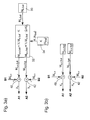
- Fig. 4 shows a corresponding embodiment, in addition to Fig. 1 respectively.
- Fig. 2 combined with Fig. 3 is referenced.
- the detection of such a specific material web properties of the respective material web side can be used to divide the total stroke actual value detected by the sensors 14 and 16 into the page-related individual line weights (actual values).
- the division or split value K supplied to the determination unit 22 is determined by the distribution or split value K supplied to the determination unit 22 Fig. 4 schematically shown arrangement 26 is determined.
- a gloss difference ⁇ G (t) is determined by a difference formation unit 54.
- an evaluation unit 56 receiving the gloss difference value an instantaneous split or split value K (t) is assigned to the gloss difference value, for example on the basis of a previously stored characteristic curve or a previously stored characteristic map or on the basis of a previously stored assignment function.
- the material web is passed after passing through the sensors 50 and 52, for example, a reel.
- a variant for the division or split value determination K on the basis of gloss measurements is in Fig. 5 shown.
- a difference-forming and normalizing unit 54 ' is provided which determines a normalized difference ⁇ (t), which is evaluated by the unit 56' in principle in the same way as by the unit 56. to provide the current split or split value K.
- a gloss measurement for example, by means of a reflectometer, the light reflected from the surface can be measured in terms of its intensity in an angular range bounded by diaphragms.
- a plurality of, for example, three angles of incidence and thus measuring ranges are used in order to eliminate or at least minimize a dependence of the reflectometer value on the angle of incidence.
- a white measurement may be based on a comparison of the light reflection between the surface to be measured and a whiteness plate serving as a white standard.
- Corresponding sensors and sensor arrangements are available from various suppliers, for example ABB Automation and Lehmann Mess-Systeme AG.
- Fig. 6 represents a generalization of the determination of the division or split value K based on the respective line weight-dependent properties of the material web.
- the material web 10 having coating application 11 O or 11 U on both sides passes through an upper sensor arrangement 50 'and a lower sensor arrangement 52', which provide measurement results S o, i and S U, i .
- a Determination unit 54 is at least one secondary size T i from at least one of the upper material web page related measurement result S O, i and at least one related to the lower material web page measurement result S U, i , for example, determines a ratio, or / and at least one secondary Size O i, J from at least two measurement results S O, i and S O, j or / and at least one secondary quantity U i, j relating to the upper material web side from at least two measurement results S U, i and S relating to the lower material web side U, j .
- i Based on one or more of the addressed secondary variables or - alternatively - on the basis of the measurement results S O, i and S U, i itself determines the evaluation unit 56 "based on stored characteristic curves or maps or a stored assignment function the currently applicable Division or split value K, which then, for example, the unit 22 according to Fig. 1 or Fig. 2 is supplied.
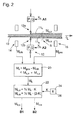
- Fig. 7 Figure 4 shows an overall system for page-wise bar weight control based on the total stroke detected and recorded gloss level of the coated web.
- the same reference numerals as used for the embodiments explained above, and only changes compared to the previously explained embodiments are explained. Otherwise, explicit reference is made to the comments above.
- the control device 60 receives the provided based on the measurement results from the sensors 14 and 16 by the difference forming unit 20 overall stroke value S M, is compared with a predetermined desired value S M, is intended.
- the desired value can be stored in a memory unit 64.
- the comparison results in a reference variable X S relating to the total line, which is provided by a control element of the control device 60.
- the control device 62 receives from the differentiating and normalizing unit 54 'the normalized gloss difference ⁇ , which is compared with a predetermined desired value ⁇ soll .
- the desired value can be stored in a memory unit 66. From the comparison results in a reference variable X ⁇ , which is provided by a control element of the control device 62.
- the reference variables X S and X ⁇ control the application unit 12 or the commissioned units 12 a and 12 b via a drive device 70 with regard to the page-related coating order.
- the control device 70, a relating to the order on the upper material web page reference variable X is O and one relating to the order on the lower material web page command value X U ready to be supplied to the application unit or on the applicators.
- the control elements and the actuating devices of the commissioned unit or the commissioned units controlled by them can be designed accordingly without further ado
- the reference variables X O and X U which directly determine the application on the upper or lower material web side are additive or subtractive from the reference variable X S relating to the overall order and the reference variable X relating to the division of the overall order onto the two material web pages ⁇ .
- page-weighted weight control there are still many forms of page-weighted weight control possible.
- a zone-by-zone rule for achieving or be provided at least to approximate a desired transverse profile of the respective stroke weight.
- gloss measurement it is also possible to provide a quotient formation instead of forming a difference (normalized or unnormalized).
- a quotient formation instead of forming a difference (normalized or unnormalized).
- the gloss measurement or whiteness measurement or other measurement with respect to the material web top and the material web underside can take place close to or at the tambour in the material web rewind station.
- Another possibility is a measurement online on the measuring frame, where, for example, the total basis weight M tot is measured.
Landscapes
- Application Of Or Painting With Fluid Materials (AREA)
- Coating Apparatus (AREA)
- Ink Jet (AREA)
- Making Paper Articles (AREA)
Claims (43)
- Machine destinée à appliquer un fluide appliqué liquide ou pâteux au moyen d'au moins un mécanisme d'application (12; 12a, 12b) sur les deux faces d'une nappe de matière (10) en déplacement, en particulier en papier ou en carton,
qui présente un ensemble de détecteurs (14, 16) qui réagit à l'application globale de fluide appliqué par unité de surface sur les deux faces de la nappe de matière (10) et/ou à au moins une grandeur qui dépend de l'application globale de fluide appliqué par unité de surface sur les deux faces de la nappe de matière,
caractérisée par
un dispositif de détermination (20, 22) raccordé à l'ensemble de détecteurs qui reçoit de l'ensemble (14, 16) de détecteurs une sortie (MRoh, Mges) qui représente, reflète ou indique une grandeur qui correspond à l'application globale de fluide appliqué par unité de surface sur les deux faces de la nappe de matière ou qui en dépend et qui, sur base de cette sortie et d'une valeur de répartition (K) qui représente une relation de répartition de l'application globale par unité de surface sur les deux faces de la nappe de matière, détermine les différentes quantités (MS,o, Ms,u) de fluide appliqué par unité de surface sur les deux faces de la nappe de matière. - Machine selon la revendication 1, caractérisée en ce que l'ensemble de détecteurs (14, 16, 50, 52; 14, 16, 50', 52') présente au moins un détecteur (50, 50; 50', 52') qui est associé à l'une des faces de la nappe de matière et qui répond à l'application séparée de fluide appliqué par unité de surface sur la face associée de la nappe de matière et/ou à une propriété de la nappe de matière qui dépend de l'application séparée de fluide appliqué par unité de surface sur la face associée de la nappe de matière.
- Machine selon la revendication 1, caractérisée en ce que l'ensemble de détecteurs (14, 16, 50, 52; 14, 16, 50', 52') présente en association à chacune des deux faces de la nappe de matière au moins un détecteur (50, 50; 50', 52') qui réagit à l'application séparée de fluide appliqué par unité de surface sur la face associée de la nappe de matière et/ou à au moins une propriété de la nappe de matière qui dépend de l'application séparée de fluide appliqué par unité de surface sur la face associée de la nappe de matière.
- Machine selon les revendications 2 ou 3, caractérisée en ce que le dispositif de détermination ou un autre dispositif de détermination (26) du dispositif de régulation reçoit de l'ensemble de détecteurs une autre sortie (Go, Gu, So,i, Su,i) qui représente, reflète ou indique l'application séparée de fluide appliqué par unité de surface sur la face de la nappe de matière associée au détecteur (50; 50; 50'; 52') ou la grandeur qui en dépend et détermine sur base de cette sortie la valeur de répartition (K) qui représente la relation de répartition de l'application globale par unité de surface sur les deux faces de la nappe de matière.
- Machine selon l'une des revendications 1 à 4, caractérisée par au moins un dispositif de régulation (20, 22, 40, 42) qui comprend le dispositif de détermination (20, 22) qui reçoit de l'ensemble de détecteurs (14, 16) la sortie (MRoh, Mges) qui représente, reflète ou indique l'application globale par unité de surface du fluide appliqué sur les deux faces de la nappe de matière ou la grandeur qui en dépend et, sur base de cette sortie, amène l'application globale (MS) de fluide appliqué par unité de surface sur les deux faces de la nappe de matière à au moins s'approcher d'une valeur globale de consigne prédéterminée ou prédéterminable, par commande du ou des mécanismes d'application.
- Machine selon la revendication 5, caractérisée en ce que la ou les machines d'application (12) permettent un réglage individuel de l'application séparée de fluide appliqué par unité de surface sur les deux faces de la nappe de matière ou en ce qu'au moins un mécanisme propre d'application (12a ou 12b) qui permet le réglage séparé des applications séparées de fluide appliqué par unité de surface sur chaque face de la nappe de matière est associé à chaque face de la nappe de matière et en ce que le dispositif de régulation (20, 22, 40, 42) comprend en association à chacune des deux faces de la nappe de matière au moins un régulateur (40 ou 42) qui, sur base de l'application séparée ((MS,o ou MS,u) par unité de surface sur chaque face de la nappe de matière déterminée par l'unité de détermination (20, 22) amène séparément les applications séparées de fluide appliqué par unité de surface au moins à s'approcher d'une valeur de consigne distincte respective, prédéterminée ou prédéterminable, par commande du mécanisme d'application ou du mécanisme d'application associé à la face concernée.
- Machine d'application d'un fluide liquide ou pâteux d'application au moyen d'au moins un mécanisme d'application (12; 12a, 12b) sur les deux faces d'une nappe de matière (10) en déplacement, en particulier en papier ou carton,
qui présente un ensemble de détecteurs (14, 16, 50, 52; 14, 16, 50', 52') qui répond à l'application globale de fluide appliqué par unité de surface sur les deux faces de la nappe de matière (10) et/ou à au moins une grandeur qui dépend de l'application globale de fluide appliqué par unité de surface sur les deux faces de la nappe de matière,
et qui présente au moins un dispositif de régulation (40, 42; 60, 62) qui reçoit de l'ensemble de détecteurs au moins une sortie (MRoh, Mges) qui représente, reflète ou indique l'application globale de fluide appliqué par unité de surface sur les deux faces de la nappe de matière ou la grandeur qui en dépend et qui, sur base de cette sortie, amène l'application globale (MS) de fluide appliqué par unité de surface sur les deux faces de la nappe de matière à au moins s'approcher d'une valeur globale de consigne prédéterminée ou prédéterminable, par commande du ou des mécanismes d'application,
caractérisée en ce que
le ou les mécanismes d'application (12) permettent un réglage individuel de l'application séparée de fluide appliqué par unité de surface sur les deux faces de la nappe de matière ou
en ce qu'un mécanisme propre d'application (12a ou 12b) qui permet le réglage individuel de l'application séparée de fluide appliqué par unité de surface sur chaque face de la nappe de matière est associé à chacune des deux faces de la nappe de matière,
en ce que l'ensemble de détecteurs présente au moins un détecteur (50, 52; 50', 52') associé à l'une des faces de la nappe de matière et qui répond à l'application séparée de fluide appliqué par unité de surface sur la face associée de la nappe de matière et/ou à au moins une propriété de la nappe de matière qui dépend de l'application séparée par unité de surface de fluide de matière sur la face associée de la nappe de matière et
en ce que le dispositif de régulation (40, 42; 60, 62) reçoit de l'ensemble de détecteurs une autre sortie (Go, Gu; So,i, Su,i) qui représente, reflète ou indique l'application séparée de fluide appliqué par unité de surface sur la face de la nappe de matière associée au détecteur ou la propriété qui en dépend et, sur base de cette sortie et en combinaison avec la sortie (MRoh, Mges) qui représente, reflète ou indique l'application globale de fluide appliqué par unité de surface sur les deux faces de la nappe de matière ou la grandeur qui en dépend, amène séparément l'application séparée de fluide appliqué par unité de surface à au moins s'approcher d'une valeur de consigne séparée respective prédéterminée ou prédéterminable par commande du mécanisme d'application ou des mécanismes d'application prévus pour les deux faces de la nappe de matière. - Machine selon la revendication 7, caractérisée en ce que l'ensemble de détecteurs présente en association à chacune des deux faces de la nappe de matière au moins un détecteur (50 ou 52; 50' ou 52') qui réagit à l'application séparée de fluide appliqué par unité de surface sur la face associée de la nappe de matière et/ou à au moins une propriété de la nappe de matière qui dépend de l'application séparée de fluide appliqué par unité de surface sur la face associée de la nappe de matière.
- Machine selon les revendications 7 ou 8, caractérisée en ce que le dispositif de régulation comporte un dispositif de détermination (20, 22) qui reçoit de l'ensemble de détecteurs au moins une sortie (MRoh, Mges) qui indique l'application globale de fluide appliqué par unité de surface sur les deux faces de la nappe de matière ou la grandeur qui en dépend et qui, sur base de cette sortie et d'une valeur de répartition (K) qui représente la relation de répartition de l'application globale par unité de surface entre les deux faces de la nappe de matière détermine les applications séparées (MS,o, MS,u) de fluide appliqué par unité de surface sur les deux faces de la nappe de matière.
- Machine selon la revendication 9, caractérisée en ce qu'en association à chacune des deux faces de la nappe de matière, le dispositif de régulation comprend au moins un régulateur (40 ou 42) qui, sur base des applications séparées (MS,o ou MS,u) par unité de surface sur chaque face de la nappe de matière déterminées par l'unité de détermination amène séparément l'application séparée de fluide appliqué par unité de surface sur chaque face de la nappe de matière à au moins s'approcher de la valeur de consigne séparée respective prédéterminée ou prédéterminable, par commande du mécanisme d'application ou des mécanismes d'application associés à chaque face.
- Machine selon les revendications 9 ou 10, caractérisée en ce que le dispositif de détermination ou un autre dispositif de détermination (26) du dispositif de régulation reçoivent de l'ensemble de détecteurs les autres sorties (Go, Gu; So,i, Su,i) qui représentent, reflètent ou indiquent l'application séparée de fluide appliqué par unité de surface sur la face de la nappe de matière associée au détecteur (50, 52; 50', 52') ou la grandeur qui en dépend et, sur base de cette sortie, détermine la valeur de répartition (K) qui représente la relation de répartition de l'application globale par unité de surface sur les deux faces de la nappe de matière.
- Machine selon l'une des revendications 7 à 11, caractérisée en ce que chaque valeur séparée de consigne (MS,o,soll, MS,u,soll) de l'application séparée de fluide appliqué par unité de surface sur les deux faces de la nappe de matière est prédéterminée ou peut l'être.
- Machine selon la revendication 12 avec référence à la revendication 10, caractérisée en ce que la commande du mécanisme d'application ou des mécanismes d'application associés à chacune des deux faces de la nappe de matière par les deux régulateurs (40, 42) en vue d'amener les applications séparées de fluide appliqué par unité de surface à s'approcher de la valeur de consigne séparée respective prédéterminée ou prédéterminable permet d'amener l'application globale de fluide appliqué par unité de surface sur les deux faces de la nappe de matière à s'approcher de la valeur de consigne globale qui correspond à la somme des valeurs de consigne séparées.
- Machine selon l'une des revendications 7 à 12, caractérisée en ce que la valeur de consigne globale (MS,soll) de l'application séparée de fluide appliqué par unité de surface est prédéterminée ou peut l'être.
- Machine selon la revendication 14, caractérisée en ce que le dispositif de détermination (32) ou un dispositif de détermination du dispositif de régulation déterminent la valeur de consigne séparée respective (MS,o,soll; MS,u,soll) des applications séparées de fluide appliqué par unité de surface sur base d'une valeur de répartition ou de la valeur de répartition (K; Ksoll) qui représente une relation de répartition de consigne de l'application globale par unité de surface sur les deux faces de la nappe de matière.
- Machine selon la revendication 15, caractérisée en ce que comme valeur de répartition qui représente la relation de répartition de consigne, une valeur de répartition de consigne (Ksoll) différente de la valeur de répartition déterminée par le dispositif de détermination est prédéterminée.
- Machine selon l'une des revendications 7 à 14, caractérisée en ce que sur au moins une face de la nappe de matière, pour au moins une propriété de la nappe de matière qui dépend de l'application séparée de fluide appliqué par unité de surface et à laquelle le détecteur associé à la face (respective) de la nappe de matière réagit, une propriété de consigne ou au moins une relation de consigne par rapport à une autre propriété de la nappe de matière sont prédéterminées ou peuvent être prédéterminées.
- Machine selon l'une des revendications 7 à 14 en référence à la revendication 8, caractérisée en ce que sur les deux faces de la nappe de matière, pour au moins une propriété de la nappe de matière qui dépend de l'application séparée de fluide appliqué par unité de surface sur la face concernée et à laquelle le détecteur (50, 52) associé à la face concernée de la nappe de matière réagit, une propriété de consigne ou au moins une relation de consigne par rapport à une autre propriété de la nappe de matière ou une relation de consigne (Δsoll) entre la propriété qui dépend de l'application séparée de fluide appliqué par unité de surface sur la face de la nappe de matière et la propriété qui dépend de l'application séparée de fluide appliqué par unité de surface de l'autre face de la nappe de matière est prédéterminée ou peut l'être.
- Machine selon les revendications 17 ou 18, caractérisée en ce que le dispositif de régulation comporte au moins un régulateur associé à chacune des deux faces de la nappe de matière et qui, sur base de la propriété de consigne ou de la relation de consigne prédéterminées et de l'autre sortie qui représente, reflète ou indique l'application séparée de fluide appliqué par unité de surface sur la face concernée de la nappe de matière ou la propriété qui en dépend, amène la propriété détectée par le détecteur concerné à au moins s'approcher de la propriété de consigne prédéterminée ou prédéterminable ou du respect de la relation de consigne prédéterminée ou prédéterminable, par commande du mécanisme d'application ou du mécanisme d'application associé à la face pour obtenir l'application séparée de fluide appliqué par unité de surface.
- Machine selon les revendications 17 ou 18 et en référence à la revendication 8, caractérisée en ce que le dispositif de régulation comprend au moins un premier régulateur (60) et au moins un deuxième régulateur (62) associés aux deux faces de la nappe de matière, lesquels régulateurs commandent conjointement, directement ou indirectement le mécanisme d'application (12) ou les mécanismes d'application (12a, 12b),
le premier régulateur (60) amenant, sur base de la valeur de consigne globale (MS,soll) de l'application séparée de fluide appliqué par unité de surface et de la sortie (MRoh, Mges) qui représente, reflète ou indique l'application globale de fluide appliqué par unité de surface sur les deux faces de la nappe de matière ou la valeur qui en dépend, de l'application globale (MS) de fluide appliqué par unité de surface sur les deux faces de la nappe de matière à au moins s'approcher de la valeur de consigne globale (MS,soll) prédéterminée ou prédéterminable,
le deuxième régulateur (62) amenant, sur base de la propriété de consigne, des propriétés de consigne, de la relation de consigne (Δsoll) ou des relations de consigne et de l'autre sortie (Go, Gu) qui représente, reflète ou indique l'application séparée de fluide appliqué par unité de surface sur la face concernée de la nappe de matière ou la propriété qui en dépend, la propriété détectée par le ou les détecteurs à au moins s'approcher de la propriété de consigne prédéterminée ou prédéterminable ou du respect de la relation de consigne (Δsoll) prédéterminée ou prédéterminable. - Machine selon la revendication 20, caractérisée en ce que le dispositif de régulation comprend un dispositif de commande (70) qui, sur base d'au moins une première sortie de régulation (XS) du premier régulateur (60) et d'au moins une deuxième sortie de régulation (XΔ) du deuxième régulateur (62), commande le mécanisme d'application ou les mécanismes d'application dans le sens d'une répartition d'une application globale prévue par la première sortie de régulation (XS) et concernant les deux faces de la nappe de matière pour obtenir deux applications séparées qui concernent chacune une seule face de la nappe de matière, et ce après formation de la deuxième sortie de régulation (XΔ).
- Machine selon l'une des revendications 1 à 21, caractérisée en ce que l'ensemble de détecteurs comprend au moins deux détecteurs (14, 16) de poids par unité de surface dont au moins l'un saisit le poids par unité de surface (MRoh) de la nappe de matière avant l'application et au moins un autre saisit le poids par unité de surface (Mges) de la nappe de matière après l'application sur les deux faces et en ce qu'un dispositif de détermination ou le dispositif de détermination (20) sont conçus de manière à déterminer en particulier le poids global enduit (MS) à partir des poids par unité de surface avant et après l'application globale de fluide appliqué par unité de surface sur les deux faces de la nappe de matière.
- Machine selon l'une des revendications 1 à 22, caractérisée en ce que l'ensemble de détecteurs comprend en association à au moins l'une des faces de la nappe de matière et de préférence en association aux deux faces de la nappe de matière au moins un détecteur (50, 52; 50', 52'), en particulier un détecteur de brillant (50, 52), un détecteur de couleur ou un détecteur de blanc, qui réagit en particulier optiquement par réflexion à l'application séparée de fluide appliqué par unité de surface sur la face associée de la nappe de matière et/ou à au moins une propriété de la nappe de matière qui dépend de l'application séparée de fluide appliqué par unité de surface sur la face associée de la nappe de matière.
- Machine selon l'une des revendications 1 à 23, en référence aux revendications 3 ou 8, caractérisée en ce qu'un dispositif de détermination ou le dispositif de détermination (54; 54'; 54'') sont conçus pour déterminer une relation, en particulier une différence ou un rapport, entre une grandeur qui concerne une face de la nappe de matière et qui représente une propriété de la nappe de matière qui dépend de l'application séparée de fluide appliqué par unité de surface sur cette face de la nappe de matière et une grandeur qui concerne l'autre face de la nappe de matière et qui représente une propriété de la nappe de matière qui dépend de l'application séparée de fluide appliqué par unité de surface sur cette face de la nappe de matière, éventuellement un rapport de blanc, un rapport de brillant, une différence de blanc ou une différence de brillant (ΔG; Δ).
- Procédé pour déterminer des applications séparées de fluide appliqué par unité de surface sur les deux faces d'une nappe de matière (10) en déplacement, en particulier en papier ou en carton, lors d'une application d'un fluide liquide ou pâteux appliqué au moyen d'au moins un mécanisme d'application (12; 12a, 12b),
dans lequel au moins une sortie (MRoh, Mges) qui représente, reflète ou indique l'application globale de fluide appliqué par unité de surface sur les deux faces de la nappe de matière ou une grandeur qui en dépend est reçue par un ensemble de détecteurs (14, 16) et dans lequel, sur base de cette sortie et d'une valeur de répartition (K) qui représente une relation de répartition de l'application globale par unité de surface sur les deux faces de la nappe de matière, les applications séparées (MS,o, MS,u) de fluide appliqué par unité de surface sur les deux faces de la nappe de matière sont déterminées. - Procédé selon la revendication 25, caractérisé en ce qu'au moins une autre sortie (Go, Gu; So,i, Su,i) qui représente, reflète ou indique l'application séparée de fluide appliqué par unité de surface sur une face de la nappe de matière ou une grandeur qui en dépend est reçue par l'ensemble de détecteurs, et sur base de cette sortie, la valeur de répartition (K) qui représente la relation de répartition de l'application globale par unité de surface sur les deux faces de la nappe de matière est déterminée.
- Procédé d'application sur les deux faces d'un fluide appliqué liquide ou pâteux au moyen d'un mécanisme d'application (12; 12a, 12b) sur une nappe de matière (10) en déplacement, en particulier en papier ou en carton,
dans lequel au moins une sortie qui représente, reflète ou indique l'application globale de fluide appliqué par unité de surface sur les deux faces de la nappe de matière ou une grandeur qui en dépend est reçue par un ensemble de détecteurs (14, 16, 50, 52; 14, 16, 50', 52') et, sur base de cette sortie, l'application globale (MS) de fluide appliqué par unité de surface sur les deux faces de la nappe de matière est au moins approchée d'une valeur de consigne globale prédéterminée ou prédéterminable, par commande du ou des mécanismes d'application,
caractérisé en ce que
au moins une autre sortie (Go, Gu; So,i, Su,i) qui représente, reflète ou indique l'application séparée de fluide appliqué par unité de surface sur une face de la nappe de matière ou une grandeur qui en dépend est reçue par l'ensemble de détecteurs, et sur base de cette sortie et en combinaison avec la sortie (MRoh, Mges) qui représente, reflète ou indique l'application globale de fluide appliqué par unité de surface sur les deux faces de la nappe de matière ou la grandeur qui en dépend, l'application séparée de fluide appliqué par unité de surface est au moins approchée individuellement d'une valeur de consigne séparée prédéterminée ou prédéterminable, par commande du mécanisme d'application ou des mécanismes d'application prévus pour les deux faces de la nappe de matière. - Procédé selon la revendication 27, caractérisé en ce que sur base de la sortie (MRoh, Mges) reçue par l'ensemble de détecteurs et qui représente, reflète ou indique l'application globale de fluide appliqué par unité de surface sur les deux faces de la nappe de matière ou la grandeur qui en dépend et d'une valeur de répartition (K) qui représente la relation de répartition de l'application globale par unité de surface sur les deux faces de la nappe de matière, les applications séparées (MS,o, MS,u) de fluide appliqué par unité de surface sont déterminées pour les deux faces de la nappe de matière.
- Procédé selon la revendication 28, caractérisé en ce que pour les deux faces de la nappe de matière, sur base des applications séparées (MS,o, MS,u) par unité de surface sur chaque face, l'application séparée de fluide appliqué par unité de surface est au moins approchée de la valeur de consigne prédéterminée ou prédéterminable respective par commande du mécanisme d'application ou du mécanisme d'application associé à la face.
- Procédé selon les revendications 28 ou 29, caractérisé en ce que sur base de l'autre sortie (Go, Gu; So,i, Su,i) qui représente, reflète ou indique l'application séparée de fluide appliqué par unité de surface sur la face concernée de la nappe de matière ou la grandeur qui en dépend, la valeur de répartition (K) qui représente la relation de répartition de l'application globale par unité de surface sur les deux faces de la nappe de matière est déterminée.
- Procédé selon l'une des revendications 27 à 30, caractérisé en ce que chaque valeur de consigne séparée (MS,o,soll, MS,u,soll) des applications séparées de fluide appliqué par unité de surface est prédéterminée pour les deux faces de la nappe de matière.
- Procédé selon la revendication 31, en référence à la revendication 29, caractérisé en ce que la commande du mécanisme d'application ou des mécanismes d'application associés à chacune des deux faces de la nappe de matière en vue de rapprocher les applications séparées de fluide appliqué par unité de surface de la valeur de consigne prédéterminée ou prédéterminable respective rapproche l'application globale de fluide appliqué par unité de surface sur les deux faces de la nappe de matière de la valeur de consigne globale qui correspond à la somme des valeurs de consigne séparées.
- Procédé selon l'une des revendications 27 à 31, caractérisé en ce que la valeur de consigne globale (MS,soll) de l'application séparée de fluide appliqué par unité de surface est prédéterminée.
- Procédé selon la revendication 33, caractérisé en ce que chaque valeur de consigne séparée (MS,o,soll, MS,u,soll) de l'application séparée de fluide appliqué par unité de surface est déterminée sur base d'une valeur de répartition ou de la valeur de répartition (K; Ksoll) qui représente une relation de répartition de consigne de l'application globale par unité de surface sur les deux faces de la nappe de matière.
- Procédé selon la revendication 34, caractérisé en ce qu'une valeur de répartition de consigne (Ksoll) différente de la valeur de répartition déterminée est prédéterminée comme valeur de répartition qui représente la relation de répartition de consigne.
- Procédé selon l'une des revendications 27 à 33, caractérisé en ce que sur au moins une face de la nappe de matière, pour au moins une propriété de la nappe de matière qui dépend de l'application individuelle de fluide appliqué par unité de surface et à laquelle au moins un détecteur de l'ensemble de détecteurs associé à la face concernée de la nappe de matière réagit, une propriété de consigne ou au moins une relation de consigne par rapport à une autre propriété de la nappe de matière sont prédéterminées.
- Procédé selon l'une des revendications 27 à 33, caractérisé en ce que sur les deux faces de la nappe de matière, pour au moins une propriété de la nappe de matière qui dépend de l'application séparée de fluide appliqué par unité de surface sur la face concernée et à laquelle le ou les détecteurs (50, 53) associés à la face concernée de la nappe de matière réagissent, une propriété de consigne ou au moins une relation de consigne par rapport à une autre propriété de la nappe de matière ou une relation de consigne (Δsoll) entre la propriété dépendant de l'application séparée de fluide appliqué par unité de surface sur une face de la nappe de matière et la propriété dépendant de l'application séparée de fluide appliqué par unité de surface sur l'autre face de la nappe de matière sont prédéterminées.
- Procédé selon les revendications 36 ou 37, caractérisé en ce que sur base de la propriété de consigne prédéterminée ou de la relation de consigne prédéterminée et de l'autre sortie qui représente, reflète ou indique l'application séparée de fluide appliqué par unité de surface sur la face concerné de la nappe de matière ou la propriété qui en dépend, la propriété saisie par le détecteur concerné est au moins approchée de la propriété de consigne prédéterminée ou prédéterminable ou du respect de la relation de consigne prédéterminée ou prédéterminable, par commande du mécanisme d'application ou du mécanisme d'application associé à la face.
- Procédé selon les revendications 36 ou 37, en référence à la revendication 33, caractérisé en ce que sur base de la valeur de consigne globale (MS,soll) de l'application séparée de fluide appliqué par unité de surface et de l'application globale de fluide appliqué par unité de surface sur les deux faces de la nappe de matière ou de la sortie (MRoh, Mges) qui représente, reflète ou indique la grandeur qui en dépend, on amène a l'application globale (MS) de fluide appliqué par unité de surface sur les deux faces de la nappe de matière à au moins s'approcher de la valeur de consigne globale prédéterminée ou prédéterminable, par émission d'au moins une sortie de régulation (XS), et en ce qu'en même temps, sur base de la propriété de consigne, des propriétés de consigne, de la relation de consigne (Δsoll) ou des relations de consigne et de l'autre sortie (Go, Gu) qui représente, reflète ou indique l'application séparée de fluide appliqué par unité de surface sur la face concerné de la nappe de matière ou la propriété qui en dépend, on amène la propriété saisie par le ou les détecteurs à au moins s'approcher de la propriété de consigne prédéterminée ou prédéterminable ou du respect de la relation de consigne (Δsoll) prédéterminée ou prédéterminable, par émission d'au moins une deuxième sortie de régulation (XΔ).
- Procédé selon la revendication 39, caractérisé en ce que sur base de la première sortie de régulation (XS) et de la deuxième sortie de régulation (XΔ), le mécanisme d'application (12) ou les mécanismes d'application (12a, 12b) sont commandés dans le sens d'une répartition de l'application globale prévue par la première sortie de régulation (XS) et qui concerne les deux faces de la nappe de matière entre deux applications séparées qui concernent chacune une face de la nappe de matière, après émission de la deuxième sortie de régulation (XΔ).
- Procédé selon l'une des revendications 25 à 40, caractérisé en ce que l'ensemble de détecteurs comprend au moins deux détecteurs (14, 16) de poids par unité de surface dont au moins l'un saisit le poids par unité de surface (MRoh) de la nappe de matière avant l'application et au moins un autre saisit le poids par unité de surface (Mges) de la nappe de matière après application sur ses deux faces et en ce qu'en particulier le poids total enduit (MS) est déterminé à partir des poids par unité de surface avant et après l'application de l'application globale de fluide appliqué par unité de surface sur les deux faces de la nappe de matière.
- Procédé selon l'une des revendications 25 à 41, caractérisé en ce que l'ensemble de détecteurs comprend en association à au moins l'une des faces de la nappe de matière et de préférence en association aux deux faces de la nappe de matière au moins un détecteur (50, 52; 50', 52'), en particulier un détecteur de brillant (50, 52), un détecteur de couleur ou un détecteur de blanc, qui réagit en particulier optiquement par réflexion à l'application séparée de fluide appliqué par unité de surface sur la face associée de la nappe de matière et/ou à au moins une propriété de la nappe de matière qui dépend de l'application séparée de fluide appliqué par unité de surface sur la face associée de la nappe de matière.
- Procédé selon l'une des revendications 25 à 42, caractérisé en ce qu'une relation, en particulier une différence ou un rapport, éventuellement un rapport de blanc, un rapport de brillant, une différence de blanc ou une différence de brillant (ΔG; Δ), entre une grandeur qui concerne une face de la nappe de matière et qui représente une propriété de la nappe de matière qui dépend de l'application séparée de fluide appliqué par unité de surface sur cette face de la nappe de matière et une grandeur qui concerne l'autre face de la nappe de matière et qui représente une propriété de la nappe de matière qui dépend de l'application séparée de fluide appliqué par unité de surface sur cette face de la nappe de matière est déterminée.
Applications Claiming Priority (2)
| Application Number | Priority Date | Filing Date | Title |
|---|---|---|---|
| DE102004003226 | 2004-01-22 | ||
| DE102004003226A DE102004003226A1 (de) | 2004-01-22 | 2004-01-22 | Maschine und Verfahren zum beidseitigen Auftragen eines flüssigen oder pastösen Auftragsmediums mittels wenigstens eines Auftragswerks auf eine laufende Materialbahn, insbesondere aus Papier oder Karton, sowie dabei verwendbares Verfahren zum Bestimmen von flächenbezogenen Einzelaufträgen |
Publications (2)
| Publication Number | Publication Date |
|---|---|
| EP1559835A1 EP1559835A1 (fr) | 2005-08-03 |
| EP1559835B1 true EP1559835B1 (fr) | 2009-04-08 |
Family
ID=34638747
Family Applications (1)
| Application Number | Title | Priority Date | Filing Date |
|---|---|---|---|
| EP05100081A Expired - Lifetime EP1559835B1 (fr) | 2004-01-22 | 2005-01-10 | Dispositif et procédé pour enduire deux faces d'une bande de matériau en mouvement avec un medium fluide ou pâteux, en particulier du papier ou du carton, ainsi qu'un procédé adapté lié pour déterminer des enductions separées relatives à la surface |
Country Status (3)
| Country | Link |
|---|---|
| EP (1) | EP1559835B1 (fr) |
| AT (1) | ATE428024T1 (fr) |
| DE (2) | DE102004003226A1 (fr) |
Families Citing this family (1)
| Publication number | Priority date | Publication date | Assignee | Title |
|---|---|---|---|---|
| FI118304B (fi) * | 2006-03-24 | 2007-09-28 | Metso Paper Inc | Menetelmä ja sovitelma päällystemäärän hallitsemiseksi kuiturainan päällystyksessä |
Family Cites Families (7)
| Publication number | Priority date | Publication date | Assignee | Title |
|---|---|---|---|---|
| DE19627456A1 (de) * | 1996-07-08 | 1998-01-15 | Voith Sulzer Papiermasch Gmbh | Auftragwerk zum direkten Auftragen eines flüssigen oder pastösen Mediums auf eine laufende Materialbahn, insbesondere aus Papier oder Karton |
| DE19637164A1 (de) * | 1996-09-12 | 1998-03-19 | Voith Sulzer Papiermasch Gmbh | Verfahren und Vorrichtung zum direkten oder indirekten Auftragen eines flüssigen oder pastösen Mediums auf eine laufende Materialbahn |
| DE19734262A1 (de) * | 1997-08-07 | 1999-02-11 | Voith Sulzer Papiermasch Gmbh | Verfahren zum direkten oder indirekten Auftragen eines flüssigen oder pastösen Mediums auf eine laufende Materialbahn, insbesondere aus Papier oder Karton |
| DE19801140A1 (de) * | 1998-01-14 | 1999-07-15 | Voith Sulzer Papiertech Patent | Vorrichtung zum direkten oder indirekten Auftrag eines flüssigen bis pastösen Auftragsmediums auf eine laufende Materialbahn sowie Betriebsverfahren für eine solche Vorrichtung |
| DE19803240A1 (de) * | 1998-01-28 | 1999-07-29 | Voith Sulzer Papiertech Patent | Farbvorhang-Auftragsvorrichtung |
| DE19831612A1 (de) * | 1998-07-14 | 2000-01-20 | Voith Sulzer Papiermasch Gmbh | Meßsystem |
| DE10253822A1 (de) * | 2002-11-18 | 2004-05-27 | Voith Paper Patent Gmbh | Verfahren und Vorrichtung zur automatischen Sensorkalibrierung |
-
2004
- 2004-01-22 DE DE102004003226A patent/DE102004003226A1/de not_active Withdrawn
-
2005
- 2005-01-10 DE DE502005007021T patent/DE502005007021D1/de not_active Expired - Lifetime
- 2005-01-10 AT AT05100081T patent/ATE428024T1/de not_active IP Right Cessation
- 2005-01-10 EP EP05100081A patent/EP1559835B1/fr not_active Expired - Lifetime
Also Published As
| Publication number | Publication date |
|---|---|
| DE102004003226A1 (de) | 2005-08-11 |
| DE502005007021D1 (de) | 2009-05-20 |
| EP1559835A1 (fr) | 2005-08-03 |
| ATE428024T1 (de) | 2009-04-15 |
Similar Documents
| Publication | Publication Date | Title |
|---|---|---|
| EP0933674B1 (fr) | Coucheuse à rideau | |
| DE19605183A1 (de) | Verfahren zur Regelung des Strichgewichtes-Querprofiles | |
| WO2020083540A1 (fr) | Procédé pour la commande et la régulation automatisées d'une machine pour l'application de lubrifiant ainsi que dispositif pour la commande et la régulation automatisées d'une machine pour l'application de lubrifiant | |
| DE3908386A1 (de) | Verfahren und vorrichtung zum beschichten von materialbahnen, insbesondere von papier- oder kartonbahnen | |
| DE202015009603U1 (de) | Auftragswerk für Papier-, Karton- oder Tissuebahn | |
| EP0482309B1 (fr) | Dispositif pour revêtir les deux faces d'un matériau en bande | |
| DE10211870B4 (de) | Verfahren zur Justierung zweier aneinander anlegbarer Walzen eines Druckwerks | |
| EP1559835B1 (fr) | Dispositif et procédé pour enduire deux faces d'une bande de matériau en mouvement avec un medium fluide ou pâteux, en particulier du papier ou du carton, ainsi qu'un procédé adapté lié pour déterminer des enductions separées relatives à la surface | |
| DE3638932C2 (fr) | ||
| WO2013037926A1 (fr) | Système de mesure et procédé de détermination et de régulation d'enduits relativement à des surfaces | |
| DE102008012072B3 (de) | Eine Vorrichtung und ein Verfahren zum formatmäßigen Auftragen von Leim bzw. Klebstoff auf Werkstücke | |
| DE8414413U1 (de) | Vorrichtung zum Auftragen einer Flüssigkeit auf eine laufende Bahn | |
| DE4436582C2 (de) | Verfahren zur Regelung einer Feuchtmittelmenge für eine Druckform einer laufenden Offsetrotationsdruckmaschine | |
| DE19756467A1 (de) | Verfahren und Vorrichtung zur Regelung der Qualität von Lackschichten | |
| DE19627456A1 (de) | Auftragwerk zum direkten Auftragen eines flüssigen oder pastösen Mediums auf eine laufende Materialbahn, insbesondere aus Papier oder Karton | |
| EP3960479B1 (fr) | Procédé d'impression de la surface d'une pièce dotée d'un décor et dispositif correspondant | |
| DE102019103703B4 (de) | Vorrichtung und Verfahren zur Beschichtung sowie Computerprogrammprodukt | |
| DE4235824A1 (de) | Verfahren zur Messung der Strichdicke beim Streichen von Papier, Vorrichtung zur Durchführung des Verfahrens und Verwendung der Vorrichtung | |
| DE102012016832A1 (de) | Farbregelung auf letzter Farbauftragswalze | |
| DE10145024A1 (de) | Verfahren und Einrichtung zum Messen der Dicke einer Flüssigkeitsschicht | |
| AT500687B1 (de) | Verfahren und vorrichtung zum beschichten von pappe | |
| AT11309U1 (de) | Vorrichtung zum ermitteln der menge an beschichtungsmittel in einzelnen beschichtungsmittelschichten beim mehrschichtigen vorhangbeschichten | |
| AT406491B (de) | Markiervorrichtung | |
| DE4307520A1 (de) | Verfahren und Vorrichtung zum Kaschieren von insbesondere Kartonagen | |
| DE102008055584B3 (de) | Verfahren und Vorrichtung zum Beschichten von bedruckten Papierbahnen |
Legal Events
| Date | Code | Title | Description |
|---|---|---|---|
| PUAI | Public reference made under article 153(3) epc to a published international application that has entered the european phase |
Free format text: ORIGINAL CODE: 0009012 |
|
| AK | Designated contracting states |
Kind code of ref document: A1 Designated state(s): AT BE BG CH CY CZ DE DK EE ES FI FR GB GR HU IE IS IT LI LT LU MC NL PL PT RO SE SI SK TR |
|
| AX | Request for extension of the european patent |
Extension state: AL BA HR LV MK YU |
|
| 17P | Request for examination filed |
Effective date: 20060203 |
|
| AKX | Designation fees paid |
Designated state(s): AT BE BG CH CY CZ DE DK EE ES FI FR GB GR HU IE IS IT LI LT LU MC NL PL PT RO SE SI SK TR |
|
| RAP1 | Party data changed (applicant data changed or rights of an application transferred) |
Owner name: VOITH PATENT GMBH |
|
| 17Q | First examination report despatched |
Effective date: 20070131 |
|
| GRAP | Despatch of communication of intention to grant a patent |
Free format text: ORIGINAL CODE: EPIDOSNIGR1 |
|
| GRAS | Grant fee paid |
Free format text: ORIGINAL CODE: EPIDOSNIGR3 |
|
| GRAA | (expected) grant |
Free format text: ORIGINAL CODE: 0009210 |
|
| AK | Designated contracting states |
Kind code of ref document: B1 Designated state(s): AT BE BG CH CY CZ DE DK EE ES FI FR GB GR HU IE IS IT LI LT LU MC NL PL PT RO SE SI SK TR |
|
| REG | Reference to a national code |
Ref country code: GB Ref legal event code: FG4D Free format text: NOT ENGLISH |
|
| REG | Reference to a national code |
Ref country code: CH Ref legal event code: EP |
|
| REG | Reference to a national code |
Ref country code: IE Ref legal event code: FG4D |
|
| REF | Corresponds to: |
Ref document number: 502005007021 Country of ref document: DE Date of ref document: 20090520 Kind code of ref document: P |
|
| REG | Reference to a national code |
Ref country code: SE Ref legal event code: TRGR |
|
| PG25 | Lapsed in a contracting state [announced via postgrant information from national office to epo] |
Ref country code: SI Free format text: LAPSE BECAUSE OF FAILURE TO SUBMIT A TRANSLATION OF THE DESCRIPTION OR TO PAY THE FEE WITHIN THE PRESCRIBED TIME-LIMIT Effective date: 20090408 |
|
| NLV1 | Nl: lapsed or annulled due to failure to fulfill the requirements of art. 29p and 29m of the patents act | ||
| REG | Reference to a national code |
Ref country code: IE Ref legal event code: FD4D |
|
| PG25 | Lapsed in a contracting state [announced via postgrant information from national office to epo] |
Ref country code: LT Free format text: LAPSE BECAUSE OF FAILURE TO SUBMIT A TRANSLATION OF THE DESCRIPTION OR TO PAY THE FEE WITHIN THE PRESCRIBED TIME-LIMIT Effective date: 20090408 Ref country code: PT Free format text: LAPSE BECAUSE OF FAILURE TO SUBMIT A TRANSLATION OF THE DESCRIPTION OR TO PAY THE FEE WITHIN THE PRESCRIBED TIME-LIMIT Effective date: 20090908 Ref country code: ES Free format text: LAPSE BECAUSE OF FAILURE TO SUBMIT A TRANSLATION OF THE DESCRIPTION OR TO PAY THE FEE WITHIN THE PRESCRIBED TIME-LIMIT Effective date: 20090719 |
|
| PG25 | Lapsed in a contracting state [announced via postgrant information from national office to epo] |
Ref country code: IS Free format text: LAPSE BECAUSE OF FAILURE TO SUBMIT A TRANSLATION OF THE DESCRIPTION OR TO PAY THE FEE WITHIN THE PRESCRIBED TIME-LIMIT Effective date: 20090808 Ref country code: PL Free format text: LAPSE BECAUSE OF FAILURE TO SUBMIT A TRANSLATION OF THE DESCRIPTION OR TO PAY THE FEE WITHIN THE PRESCRIBED TIME-LIMIT Effective date: 20090408 Ref country code: NL Free format text: LAPSE BECAUSE OF FAILURE TO SUBMIT A TRANSLATION OF THE DESCRIPTION OR TO PAY THE FEE WITHIN THE PRESCRIBED TIME-LIMIT Effective date: 20090408 |
|
| PG25 | Lapsed in a contracting state [announced via postgrant information from national office to epo] |
Ref country code: RO Free format text: LAPSE BECAUSE OF FAILURE TO SUBMIT A TRANSLATION OF THE DESCRIPTION OR TO PAY THE FEE WITHIN THE PRESCRIBED TIME-LIMIT Effective date: 20090408 Ref country code: DK Free format text: LAPSE BECAUSE OF FAILURE TO SUBMIT A TRANSLATION OF THE DESCRIPTION OR TO PAY THE FEE WITHIN THE PRESCRIBED TIME-LIMIT Effective date: 20090408 Ref country code: EE Free format text: LAPSE BECAUSE OF FAILURE TO SUBMIT A TRANSLATION OF THE DESCRIPTION OR TO PAY THE FEE WITHIN THE PRESCRIBED TIME-LIMIT Effective date: 20090408 Ref country code: IE Free format text: LAPSE BECAUSE OF FAILURE TO SUBMIT A TRANSLATION OF THE DESCRIPTION OR TO PAY THE FEE WITHIN THE PRESCRIBED TIME-LIMIT Effective date: 20090408 Ref country code: CZ Free format text: LAPSE BECAUSE OF FAILURE TO SUBMIT A TRANSLATION OF THE DESCRIPTION OR TO PAY THE FEE WITHIN THE PRESCRIBED TIME-LIMIT Effective date: 20090408 |
|
| PGFP | Annual fee paid to national office [announced via postgrant information from national office to epo] |
Ref country code: SE Payment date: 20091223 Year of fee payment: 6 |
|
| PLBE | No opposition filed within time limit |
Free format text: ORIGINAL CODE: 0009261 |
|
| STAA | Information on the status of an ep patent application or granted ep patent |
Free format text: STATUS: NO OPPOSITION FILED WITHIN TIME LIMIT |
|
| PG25 | Lapsed in a contracting state [announced via postgrant information from national office to epo] |
Ref country code: SK Free format text: LAPSE BECAUSE OF FAILURE TO SUBMIT A TRANSLATION OF THE DESCRIPTION OR TO PAY THE FEE WITHIN THE PRESCRIBED TIME-LIMIT Effective date: 20090408 |
|
| 26N | No opposition filed |
Effective date: 20100111 |
|
| PG25 | Lapsed in a contracting state [announced via postgrant information from national office to epo] |
Ref country code: BG Free format text: LAPSE BECAUSE OF FAILURE TO SUBMIT A TRANSLATION OF THE DESCRIPTION OR TO PAY THE FEE WITHIN THE PRESCRIBED TIME-LIMIT Effective date: 20090708 |
|
| PGFP | Annual fee paid to national office [announced via postgrant information from national office to epo] |
Ref country code: FI Payment date: 20100115 Year of fee payment: 6 |
|
| PGFP | Annual fee paid to national office [announced via postgrant information from national office to epo] |
Ref country code: AT Payment date: 20100114 Year of fee payment: 6 Ref country code: DE Payment date: 20100121 Year of fee payment: 6 |
|
| BERE | Be: lapsed |
Owner name: VOITH PATENT G.M.B.H. Effective date: 20100131 |
|
| PG25 | Lapsed in a contracting state [announced via postgrant information from national office to epo] |
Ref country code: MC Free format text: LAPSE BECAUSE OF NON-PAYMENT OF DUE FEES Effective date: 20100131 |
|
| REG | Reference to a national code |
Ref country code: CH Ref legal event code: PL |
|
| GBPC | Gb: european patent ceased through non-payment of renewal fee |
Effective date: 20100110 |
|
| REG | Reference to a national code |
Ref country code: FR Ref legal event code: ST Effective date: 20100930 |
|
| PG25 | Lapsed in a contracting state [announced via postgrant information from national office to epo] |
Ref country code: CH Free format text: LAPSE BECAUSE OF NON-PAYMENT OF DUE FEES Effective date: 20100131 Ref country code: LI Free format text: LAPSE BECAUSE OF NON-PAYMENT OF DUE FEES Effective date: 20100131 Ref country code: GR Free format text: LAPSE BECAUSE OF FAILURE TO SUBMIT A TRANSLATION OF THE DESCRIPTION OR TO PAY THE FEE WITHIN THE PRESCRIBED TIME-LIMIT Effective date: 20090709 Ref country code: FR Free format text: LAPSE BECAUSE OF NON-PAYMENT OF DUE FEES Effective date: 20100201 |
|
| PG25 | Lapsed in a contracting state [announced via postgrant information from national office to epo] |
Ref country code: GB Free format text: LAPSE BECAUSE OF NON-PAYMENT OF DUE FEES Effective date: 20100110 |
|
| PG25 | Lapsed in a contracting state [announced via postgrant information from national office to epo] |
Ref country code: BE Free format text: LAPSE BECAUSE OF NON-PAYMENT OF DUE FEES Effective date: 20100131 |
|
| PG25 | Lapsed in a contracting state [announced via postgrant information from national office to epo] |
Ref country code: IT Free format text: LAPSE BECAUSE OF FAILURE TO SUBMIT A TRANSLATION OF THE DESCRIPTION OR TO PAY THE FEE WITHIN THE PRESCRIBED TIME-LIMIT Effective date: 20090408 |
|
| REG | Reference to a national code |
Ref country code: SE Ref legal event code: EUG |
|
| PG25 | Lapsed in a contracting state [announced via postgrant information from national office to epo] |
Ref country code: AT Free format text: LAPSE BECAUSE OF NON-PAYMENT OF DUE FEES Effective date: 20110110 Ref country code: FI Free format text: LAPSE BECAUSE OF NON-PAYMENT OF DUE FEES Effective date: 20110110 |
|
| REG | Reference to a national code |
Ref country code: DE Ref legal event code: R119 Ref document number: 502005007021 Country of ref document: DE Effective date: 20110802 |
|
| PG25 | Lapsed in a contracting state [announced via postgrant information from national office to epo] |
Ref country code: CY Free format text: LAPSE BECAUSE OF FAILURE TO SUBMIT A TRANSLATION OF THE DESCRIPTION OR TO PAY THE FEE WITHIN THE PRESCRIBED TIME-LIMIT Effective date: 20090408 |
|
| PG25 | Lapsed in a contracting state [announced via postgrant information from national office to epo] |
Ref country code: HU Free format text: LAPSE BECAUSE OF FAILURE TO SUBMIT A TRANSLATION OF THE DESCRIPTION OR TO PAY THE FEE WITHIN THE PRESCRIBED TIME-LIMIT Effective date: 20091009 Ref country code: LU Free format text: LAPSE BECAUSE OF NON-PAYMENT OF DUE FEES Effective date: 20100110 |
|
| PG25 | Lapsed in a contracting state [announced via postgrant information from national office to epo] |
Ref country code: TR Free format text: LAPSE BECAUSE OF FAILURE TO SUBMIT A TRANSLATION OF THE DESCRIPTION OR TO PAY THE FEE WITHIN THE PRESCRIBED TIME-LIMIT Effective date: 20090408 |
|
| PG25 | Lapsed in a contracting state [announced via postgrant information from national office to epo] |
Ref country code: SE Free format text: LAPSE BECAUSE OF NON-PAYMENT OF DUE FEES Effective date: 20110111 |
|
| PG25 | Lapsed in a contracting state [announced via postgrant information from national office to epo] |
Ref country code: DE Free format text: LAPSE BECAUSE OF NON-PAYMENT OF DUE FEES Effective date: 20110802 |