EP1559910A1 - Eolienne à axe horizontal et procédé pour contrôller une éolienne à axe horizontal - Google Patents
Eolienne à axe horizontal et procédé pour contrôller une éolienne à axe horizontal Download PDFInfo
- Publication number
- EP1559910A1 EP1559910A1 EP05001820A EP05001820A EP1559910A1 EP 1559910 A1 EP1559910 A1 EP 1559910A1 EP 05001820 A EP05001820 A EP 05001820A EP 05001820 A EP05001820 A EP 05001820A EP 1559910 A1 EP1559910 A1 EP 1559910A1
- Authority
- EP
- European Patent Office
- Prior art keywords
- rotor
- wind
- yaw angle
- anemometers
- anemometer
- Prior art date
- Legal status (The legal status is an assumption and is not a legal conclusion. Google has not performed a legal analysis and makes no representation as to the accuracy of the status listed.)
- Granted
Links
- 238000000034 method Methods 0.000 title claims description 22
- 238000005259 measurement Methods 0.000 description 9
- 238000007664 blowing Methods 0.000 description 4
- 230000000694 effects Effects 0.000 description 3
- 230000006870 function Effects 0.000 description 3
- 238000013459 approach Methods 0.000 description 2
- 238000012423 maintenance Methods 0.000 description 2
- 238000004519 manufacturing process Methods 0.000 description 2
- 238000012876 topography Methods 0.000 description 2
- 238000002474 experimental method Methods 0.000 description 1
- 238000012360 testing method Methods 0.000 description 1
Images

Classifications
-
- F—MECHANICAL ENGINEERING; LIGHTING; HEATING; WEAPONS; BLASTING
- F03—MACHINES OR ENGINES FOR LIQUIDS; WIND, SPRING, OR WEIGHT MOTORS; PRODUCING MECHANICAL POWER OR A REACTIVE PROPULSIVE THRUST, NOT OTHERWISE PROVIDED FOR
- F03D—WIND MOTORS
- F03D7/00—Controlling wind motors
- F03D7/02—Controlling wind motors the wind motors having rotation axis substantially parallel to the air flow entering the rotor
- F03D7/0204—Controlling wind motors the wind motors having rotation axis substantially parallel to the air flow entering the rotor for orientation in relation to wind direction
-
- F—MECHANICAL ENGINEERING; LIGHTING; HEATING; WEAPONS; BLASTING
- F05—INDEXING SCHEMES RELATING TO ENGINES OR PUMPS IN VARIOUS SUBCLASSES OF CLASSES F01-F04
- F05B—INDEXING SCHEME RELATING TO WIND, SPRING, WEIGHT, INERTIA OR LIKE MOTORS, TO MACHINES OR ENGINES FOR LIQUIDS COVERED BY SUBCLASSES F03B, F03D AND F03G
- F05B2240/00—Components
- F05B2240/40—Use of a multiplicity of similar components
-
- F—MECHANICAL ENGINEERING; LIGHTING; HEATING; WEAPONS; BLASTING
- F05—INDEXING SCHEMES RELATING TO ENGINES OR PUMPS IN VARIOUS SUBCLASSES OF CLASSES F01-F04
- F05B—INDEXING SCHEME RELATING TO WIND, SPRING, WEIGHT, INERTIA OR LIKE MOTORS, TO MACHINES OR ENGINES FOR LIQUIDS COVERED BY SUBCLASSES F03B, F03D AND F03G
- F05B2260/00—Function
- F05B2260/82—Forecasts
- F05B2260/821—Parameter estimation or prediction
-
- F—MECHANICAL ENGINEERING; LIGHTING; HEATING; WEAPONS; BLASTING
- F05—INDEXING SCHEMES RELATING TO ENGINES OR PUMPS IN VARIOUS SUBCLASSES OF CLASSES F01-F04
- F05B—INDEXING SCHEME RELATING TO WIND, SPRING, WEIGHT, INERTIA OR LIKE MOTORS, TO MACHINES OR ENGINES FOR LIQUIDS COVERED BY SUBCLASSES F03B, F03D AND F03G
- F05B2270/00—Control
- F05B2270/30—Control parameters, e.g. input parameters
- F05B2270/32—Wind speeds
-
- F—MECHANICAL ENGINEERING; LIGHTING; HEATING; WEAPONS; BLASTING
- F05—INDEXING SCHEMES RELATING TO ENGINES OR PUMPS IN VARIOUS SUBCLASSES OF CLASSES F01-F04
- F05B—INDEXING SCHEME RELATING TO WIND, SPRING, WEIGHT, INERTIA OR LIKE MOTORS, TO MACHINES OR ENGINES FOR LIQUIDS COVERED BY SUBCLASSES F03B, F03D AND F03G
- F05B2270/00—Control
- F05B2270/30—Control parameters, e.g. input parameters
- F05B2270/329—Azimuth or yaw angle
-
- Y—GENERAL TAGGING OF NEW TECHNOLOGICAL DEVELOPMENTS; GENERAL TAGGING OF CROSS-SECTIONAL TECHNOLOGIES SPANNING OVER SEVERAL SECTIONS OF THE IPC; TECHNICAL SUBJECTS COVERED BY FORMER USPC CROSS-REFERENCE ART COLLECTIONS [XRACs] AND DIGESTS
- Y02—TECHNOLOGIES OR APPLICATIONS FOR MITIGATION OR ADAPTATION AGAINST CLIMATE CHANGE
- Y02E—REDUCTION OF GREENHOUSE GAS [GHG] EMISSIONS, RELATED TO ENERGY GENERATION, TRANSMISSION OR DISTRIBUTION
- Y02E10/00—Energy generation through renewable energy sources
- Y02E10/70—Wind energy
- Y02E10/72—Wind turbines with rotation axis in wind direction
Definitions
- the present invention relates to a horizontal axis wind turbine and a method for controlling a horizontal axis wind turbine.
- horizontal axis wind turbines have been proposed and in practical use in order to generate electric power from natural wind.
- a horizontal axis wind turbine is provided with a yaw sensor, such as a yaw vane, for measuring the direction of the wind blowing against the rotor (wind direction).
- a control device of the horizontal axis wind turbine performs "yaw control" of starting rotation of the rotor as well as rotates the rotor axis in a substantially horizontal plane in such a way that the rotor faces to the wind direction measured by the yaw sensor, i.e. the yaw angle (the angle between the direction of the rotor axis and the wind direction) is made to converge to about 0 degree.
- a yaw sensor 200 of the upwind turbine is generally located from a substantial central portion to a posterior portion of the rotor axis direction of the upper portion of a nacelle 300.
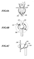
- FIG. 5 shows measurement errors of a yaw angle caused by such an upflow angle and is a graph showing results of a wind tunnel test of measurement values of the yaw angle in case of locating the yaw sensor 200 on the upper portion of the nacelle 300 as shown in FIGS. 4A to 4C.
- FIG. 5 shows measurement errors of a yaw angle caused by such an upflow angle and is a graph showing results of a wind tunnel test of measurement values of the yaw angle in case of locating the yaw sensor 200 on the upper portion of the nacelle 300 as shown in FIGS. 4A to 4C.
- the horizontal coordinate is a value of a yaw angle ⁇ in case of an upflow angle of 0 degree (hereinafter referred to as a "true yaw angle value”) and the vertical coordinate is a difference between a value of the yaw angle ⁇ measured by the yaw sensor 200 in case of an upflow angle of 0 degree to +30 degree and a value of the yaw angle ⁇ in case of an upflow angle of 0 degree (hereinafter referred as to a "yaw angle measurement error”.
- a yaw angle measurement error (the vertical coordinate) changes from about -30 degree to about +10 degree by about +40 degree corresponding to a true yaw angle value (the horizontal coordinate) changing from 0 degree to +10 degree by + 10 degree (see FIG. 5: curve E). That is, a value of the yaw angle ⁇ measured by the yaw sensor 200 is measured as changing by about +50 degree, corresponding to a value of the actual yaw angle ⁇ changing by +10 degree. Therefore yaw control of the rotor 100 is repeated although the change of the wind direction is slight.
- Such measurement errors of a yaw angle caused by an upflow angle can be reduced slightly by locating the yaw sensor 200 at a high position not to be affected by the nacelle 300.
- the yaw sensor 200 shakes easily, its durability is degraded and a more cost is required because this means makes a supporting rod 210 supporting the yaw sensor 200 very long.
- An object of the present invention is to achieve accurate yaw control in a horizontal axis wind turbine of an upwind type installed at a site where an upflow is often generated.
- a horizontal axis wind turbine of an upwind type comprises: a rotor for rotating around a rotor axis extending in a horizontal direction, the rotor being turned in a horizontal plane according to a wind direction; a nacelle having a symmetrical shape with respect to an imaginary plane including the rotor axis and extending a vertical direction; two anemometers disposed at positions of both side portions of the nacelle, the positions opposing each other across the imaginary plane; and a controller for controlling a yaw angle of the rotor based on wind speeds measured by the two anemometers.
- difference is generated in wind speeds measured by the two anemometers regardless of the presence or absence of an upflow when the rotor does not face opposite the wind direction because of comprising a nacelle having a symmetrical shape with respect to an imaginary plane including the rotor axis and extending a vertical direction and two anemometers disposed at positions of both side portions of the nacelle which oppose each other across the imaginary plane.
- the controller controls the yaw angle of the rotor based on the wind speeds measured by the two anemometers in this way.
- the yaw angle of the rotor based on the difference or ratio of the wind speed measured by the two anemometers and turn the rotor in the horizontal plane so that the estimated yaw angle converges to 0 degree (so that the rotor faces opposite the wind direction).
- the controller estimates the yaw angle of the rotor based on at least one of a difference and a ratio of the wind speeds measured by the two anemometer, and turns the rotor so that the estimated yaw angle converges to 0 degree.
- the yaw angle of the rotor is estimated based on the difference or ratio of the wind speed measured by the two anemometers. Then, it is possible to turn the rotor in the horizontal plane so that the estimated yaw angle converges to 0 degree (i.e. so as to make the rotor face opposite the wind direction).
- a method for controlling the wind turbine comprises: estimating the yaw angle of the rotor based on at least one of a difference and a ratio of the wind speeds measured by the two anemometers; and turning the rotor so that the estimated yaw converges to 0 degree.
- the yaw angle of the rotor is estimated based on the difference or ratio of the wind speed measured by the two anemometers. Then, it is possible to turn the rotor in the horizontal plane so that the estimated yaw angle converges to 0 degree (i.e. so as to make the rotor face opposite the wind direction).
- a method for controlling the wind turbine comprises: determining whether a difference of the wind speeds measured by the two anemometers is not more than a predetermined threshold; turning the rotor to one anemometer which measures a higher wind speed than other anemometer, when the difference of the wind speeds exceeds the threshold; and stopping the turning of the rotor when the difference of the wind speeds falls not more than the threshold.
- the rotor when the difference of the wind speeds measured by the two anemometers exceeds the threshold, the rotor is turned to the anemometer measuring a higher value than the other anemometer, and when the wind speed difference falls not more than the threshold, the turning of the rotor is stopped. Accordingly, it is possible to achieve the yaw control by an incredibly simple control logic using values of the wind speeds measured by the two anemometers.
- a method for controlling the wind turbine comprises turning the rotor to equalize the wind speeds measured by the two anemometers.
- the rotor can be made to face opposite the wind direction by turning the rotor to equalize values of the wind speeds measured by the two anemometers.
- a horizontal axis wind turbine comprises: a rotor for rotating around a rotor axis extending in a horizontal direction; a nacelle having a symmetrical shape with respect to an imaginary plane including the rotor axis and extending a vertical direction; two anemometers disposed at both side portions so that wind speeds measured by the anemometers are different except when a yaw angle of the rotor is 0 degree; and a controller for controlling the yaw angle of the rotor based on the wind speeds measured by the two anemometer.
- the wind turbine is a horizontal axis wind turbine of an upwind type.
- the controller controls the yaw angle based on at least one of a difference and a ratio between the wind speeds measured by the two anemometers.
- the controller compares the wind speeds measured by the two anemometers and turns the rotor to one anemometer which measures a higher wind speed than other anemometer.
- the controller calculates a control determination value from the wind speeds measured by the two anemometers; determines whether the control determination value is within a predetermined range or not; turns the rotor to an anemometer which measures a higher wind speed than other anemometer, when the control determination value is out of the predetermined range; and stops turning the rotor when the control determination value comes within the range.
- the controller determines whether a difference of the wind speeds measured by the two anemometers is not more than a predetermined threshold; turns the rotor to one anemometer which measures a higher wind speed than other anemometer, when the difference of the wind speeds exceeds the threshold; and stops turning the rotor when the difference of the wind speeds falls not more than the threshold.
- the controller estimates the yaw angle of the rotor based on the wind speeds measured by the two anemometers, and turns the rotor so that the estimated yaw angle converges to 0 degree.
- the controller turns the rotor to equalize the wind speeds measured by the two anemometers.
- a method for controlling the wind turbine comprises:
- a method for controlling the wind turbine comprises:
- a method for controlling the wind turbine comprises:
- a method for controlling the wind turbine comprises:
- a method for controlling the wind turbine comprises:
- a method for controlling the wind turbine comprises:
- difference is generated in wind speeds measured by the two anemometers regardless of the presence or absence of an upflow because respective anemometers are disposed in the both side portions.
- the yaw control of the rotor can be performed based on difference or ratio of the wind speeds measured by the two anemometers. Accordingly, it is possible to achieve accurate yaw control by using the two anemometers even in case of the horizontal axis wind turbine installed at a site where an upflow is often generate.
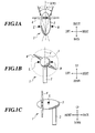
- FIGS. 1A to 1C a downwind horizontal axis wind turbine 1 shown in FIGS. 1A to 1C is adopted as an example of a horizontal axis wind turbine.
- the horizontal axis wind turbine 1 comprises: a tower 2 installed at a predetermined site; a nacelle 3 attached to the top of the tower 2 rotatably in a substantially horizontal plane; a main shaft (not shown) extending in a substantially horizontal direction inside the nacelle 3; a rotor 4 attached to the main shaft; an anemometer L and an anemometer R attached to both side portions of the nacelle 3; a control device (not shown) for integrating and controlling the whole of the horizontal axis wind turbine 1; and the like.
- the nacelle 3 has, as shown in FIGS. 1A to 1C, a symmetrical form with respect to an imaginary plane V including the rotor axis X of a rotor 4 and extending in the vertical direction.
- the anemometer L is disposed on the left-side portion of the nacelle 3 and the anemometer R is disposed on the right-side portion.
- the anemometer L and anemometer R are disposed at the positions that substantially oppose to each other with the imaginary plane V between them.
- rotation anemometers in which a plurality of cups catch the wind blowing against the rotor center of the horizontal axis wind turbine 1 and the wind speed is measured from the speed thereof are adopted as the anemometer L and the anemometer R.
- the type of the anemometer L and the anemometer R is not limited in particular. Therefore the type used conventionally (for example, the type of the anemometer manufactured by Vaisala or Thies) may be adopted.
- the control device performs a calculation process for calculating a difference (hereinafter, referred to as "wind speed difference”) or a ratio (hereinafter, referred to as “wind speed ratio”) between a value of the wind speed measured by the anemometer L and a value of the wind speed measured by the anemometer R, an estimation process for estimating the yaw angle ⁇ by using the wind speed difference correlation data or the wind speed ratio correlation data, which will be explained below, by executing the predetermined programs. Additionally, the control device controls the yaw angle ⁇ of the rotor 4 based on the wind speeds measured by the anemometer L and the anemometer R. That is, the control device is the controller of the present invention.
- the anemometer L and the anemometer R are disposed on the both side portions of the nacelle 3. Therefore a difference is generated between a value of the wind speed measured by the anemometer L and a value of the wind speed measured by the anemometer R in the case that the wind blows diagonally from the front of rotor 4. The same is true in the case that an upflow having an upflow angle blows against the rotor 4.
- the effect of the nacelle 3 makes a value of the wind speed measured by the anemometer L higher than a value the wind speed measured by the anemometer R in the case that the yaw angle ⁇ is plus (+), that is, the wind blows from the left side of the rotor axis X of the rotor 4.
- the effect of the nacelle 3 makes a value of the wind speed measured by the anemometer L lower than a value of the wind speed measured by the anemometer R in the case that the yaw angle ⁇ is minus (-), that is, the wind blows from the right side of the rotor axis X.
- data according to the relationship between the wind speed difference and the yaw angle ⁇ (wind speed difference correlation data) and data according to the relationship between the wind speed ratio and the yaw angle ⁇ (wind speed ratio correlation data) are obtained by means of ground-based experiments in advance.
- the wind speed difference correlation data and the wind speed ratio correlation data are stored in the memory in the nacelle 3.
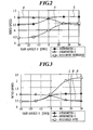
- the graph showing relationship between the difference in the wind speeds and the yaw angle ⁇ shown in FIG. 2 may be employed as the wind speed difference correlation data.
- the vertical coordinate is "wind speed” and the horizontal coordinate is “yaw angle ⁇ (degree)”.
- Values of "wind speed" of vertical coordinate in FIG. 2 are ratios (non-dimensional values) of measured values to the wind speed.
- a curve L in FIG. 2 is formed by plotting a point on a graph at the wind speed value measured by the anemometer L in each case that the yaw angle ⁇ is "-30 degree", “-15 degree”, “0 degree”, “15 degree”, and “30 degree” and by connecting these points with an approximating curve.
- the wind speed value measured by the anemometer L becomes the minimum at an yaw angle ⁇ of "-30 degree", increases gradually as the yaw angle ⁇ changes from a minus to a plus, and converges to "1" (an uniform flow) at the yaw angle ⁇ approaching about "15 degree”(see FIG. 2).
- the reason is that the wind is blocked because the anemometer L lies behind the nacelle 3 in the case that the yaw angle ⁇ is minus.
- a curve R in FIG. 2 is formed by plotting a point on a graph at the wind speed value measured by the anemometer R in each case that the yaw angle ⁇ is "-30 degree", “-15 degree”, “0 degree”, “15 degree”, and “30 degree” and by connecting these points with an approximating curve.
- the wind speed value measured by the anemometer R becomes the minimum at an yaw angle ⁇ of "30 degree", increases gradually as the yaw angle ⁇ changes from a plus to a minus, and converges to "1" (an uniform flow) at the yaw angle ⁇ approaching about "-15 degree”(see FIG. 2).
- the reason is that the wind is blocked because the anemometer R lies behind the nacelle 3 in the case that the yaw angle ⁇ is plus.
- a curve A in FIG. 2 is formed by plotting a point on a graph at a value that is the wind speed value measured by the anemometer L minus the wind speed value measured by the anemometer R (wind speed difference) in each case that the yaw angle ⁇ is "-30 degree", “-15 degree”, “0 degree”, “15 degree”, and “30 degree” and by connecting these points with an approximating curve.
- the wind speed difference corresponds to the yaw angle ⁇ due to the curve A.
- the yaw angle ⁇ may be estimated by using the curve A and the wind speed difference calculated from measurement of values of the wind speed by the anemometer L and the anemometer R. For example, if the wind speed difference is "0.5", the yaw angle ⁇ is estimated at "about 15 degree or more" (see FIG. 2).
- the value measured by the anemometer L or the anemometer R may be used as the wind speed.
- the control device is made to store data using the values measured by the anemometer L or the anemometer R as a wind speed.
- a greater value of the values measured by the anemometer L and the anemometer R may be also used as a substitute for the wind speed.
- the graph showing relationship between the ratio between the wind speeds and the yaw angle ⁇ shown in FIG. 3 may be employed as the wind speed ratio correlation data.
- the vertical coordinate is "wind speed” and the horizontal coordinate is "yaw angle ⁇ (degree)”.
- Values of "wind speed" of vertical coordinate in FIG. 3 are ratios (non-dimensional values) of measured values to wind speed undisturbed by the wind turbine.
- a curve L and a curve R in FIG. 3 are the same as the curve L and the curve R in FIG. 2 (only the scale of the vertical coordinate is changed).
- a curve B in FIG. 3 is formed by plotting a point on a graph at a value that equals the wind speed value measured by the anemometer L divided by the wind speed value measured by the anemometer R (wind speed ratio) in each case that the yaw angle ⁇ is "-30 degree", “-15 degree”, “0 degree”, “15 degree”, and “30 degree” and by connecting these points with an approximating curve.
- the wind speed ratio corresponds to the yaw angle ⁇ due to the curve B.
- the yaw angle ⁇ may be estimated by using the curve B and the wind speed ratio calculated from measurement of values of the wind speed by the anemometer L and the anemometer R. For example, if the wind speed ratio is "2", the yaw angle ⁇ is estimated at "about 15 degree"(see FIG. 3).
- the control device of the horizontal axis wind turbine 1 calculates the difference (wind speed difference) between a value of the wind speed measured by the anemometer L and a value of the wind speed measured by the anemometer R (step for calculating the wind speed difference). Then the control device estimates the yaw angle ⁇ by using the curve A of the graph showing relationship between the difference in the wind speeds and the yaw angle ⁇ (see FIG. 2) stored in the memory, and the wind speed difference calculated in the step for calculating a wind speed difference (step for estimating the yaw angle).
- the control device turns the rotor 4 in a substantially horizontal plane based on the yaw angle ⁇ estimated in the step for estimating the yaw angle.
- the yaw angle ⁇ is plus (+)
- the rotor axis X of the rotor 4 is rotated to the anemometer L in such a way that the yaw angle ⁇ becomes 0 degree.
- the rotor axis X of the rotor 4 is rotated to the anemometer L in such a way that the yaw angle ⁇ converges to 0 degree.
- the rotor is stopped (step for controlling the yaw angle).
- a step for calculating the ratio (wind speed ratio) between values of the wind speed measured by the anemometers L and R may be adopted instead of the step for calculating a wind speed difference.
- the control device estimates the yaw angle ⁇ with the curve B of the graph showing the relationship between the ratio between the wind speeds and the yaw angle ⁇ (see FIG. 3) stored in the memory, and with the wind speed ratio calculated in the step for calculating the wind speed ratio.
- the horizontal axis wind turbine 1 comprises the nacelle 3 having a symmetrical form with respect to an imaginary plane V including the rotor axis X of a rotor 4 and extending in the vertical direction, and the two anemometers (anemometer L and anemometer R) disposed at the positions of the both sides of the nacelle 3 which substantially oppose to each other with the imaginary plane V between them. Accordingly, difference is generated in wind speeds measured by the two anemometers regardless of the presence or absence of an upflow when the rotor does not face opposite the wind direction.
- the control device can estimate the yaw angle ⁇ based on the difference (or the ratio) between the wind speeds measured thus by the two anemometers (anemometer L and the anemometer R), and turn the rotor 4 in the substantially horizontal plane in such a way that the yaw angle ⁇ converges to 0 degree (the rotor 4 faces opposite the wind direction).
- the above-described embodiment adopts the control logic of estimating the yaw angle ⁇ by using the correlation data of the difference or the ratio between the wind speeds and rotating the rotor axis X in such a way that the yaw angle ⁇ converges to 0 degree. Meanwhile it is also possible to perform control of the yaw angle ⁇ of the rotor 4 referring only values of the wind speed measured by the anemometer L and the anemometer R.
- a predetermined threshold For example, whether the difference (wind speed difference) between a value measured by the anemometer L and a value measured by the anemometer R is not more than a predetermined threshold is determined (a step for determining the wind speed deference). If the wind speed difference is not more than the threshold, it is determined that the rotor 4 faces to the wind direction, and then the control finishes. Meanwhile if the wind speed difference is beyond said threshold, the rotor axis X is rotated to the anemometer measuring a higher value than the other anemometer. Then the wind speed difference falls not more than the threshold, it is determined that the rotor 4 faces to the wind direction, and then the rotor 4 is stopped (step for yaw control).
- a value for determining whether the rotor axis X is rotated or not is not limited to the wind speed difference or ratio.
- Adoption of the control logic makes it possible that yaw control with a very simple control logic using values of wind speeds measured by two anemometers (the anemometer L and the anemometer R), without using correlation data of the difference between wind speeds or correlation data of the ratio between wind speeds, and without a step for estimating the yaw angle.
- the rotor 4 can be made to face opposite the wind direction by turning the rotor 4 to equalize a value of the wind speed measured by the anemometer L and a value of the wind speed measured by the anemometer R.
- This control logic corresponds to the case that the above-described threshold of wind speed difference is set to "zero".
- the wind speed difference or ratio may be replaced by a value calculated from the wind speeds by such a suitable function as a logarithmic function or a suitable combination of functions.
Landscapes
- Engineering & Computer Science (AREA)
- Life Sciences & Earth Sciences (AREA)
- Sustainable Development (AREA)
- Sustainable Energy (AREA)
- Chemical & Material Sciences (AREA)
- Combustion & Propulsion (AREA)
- Mechanical Engineering (AREA)
- General Engineering & Computer Science (AREA)
- Wind Motors (AREA)
Applications Claiming Priority (2)
| Application Number | Priority Date | Filing Date | Title |
|---|---|---|---|
| JP2004021180A JP4589633B2 (ja) | 2004-01-29 | 2004-01-29 | 水平軸風車及び水平軸風車の制御方法 |
| JP2004021180 | 2004-01-29 |
Publications (2)
| Publication Number | Publication Date |
|---|---|
| EP1559910A1 true EP1559910A1 (fr) | 2005-08-03 |
| EP1559910B1 EP1559910B1 (fr) | 2010-11-03 |
Family
ID=34650813
Family Applications (1)
| Application Number | Title | Priority Date | Filing Date |
|---|---|---|---|
| EP05001820A Expired - Lifetime EP1559910B1 (fr) | 2004-01-29 | 2005-01-28 | Eolienne à axe horizontal et procédé pour contrôller une éolienne à axe horizontal |
Country Status (5)
| Country | Link |
|---|---|
| US (1) | US7244100B2 (fr) |
| EP (1) | EP1559910B1 (fr) |
| JP (1) | JP4589633B2 (fr) |
| DE (1) | DE602005024467D1 (fr) |
| ES (1) | ES2355804T3 (fr) |
Cited By (12)
| Publication number | Priority date | Publication date | Assignee | Title |
|---|---|---|---|---|
| EP2182205A1 (fr) | 2008-10-28 | 2010-05-05 | Siemens Aktiengesellschaft | Agencement d'éolienne et procédé d'alignement d'une éolienne avec la direction du vent |
| EP2202407A3 (fr) * | 2008-12-23 | 2011-12-28 | General Electric Company | Détermination de l'orientation en lacet d'une éolienne |
| CN101568721B (zh) * | 2007-05-25 | 2012-01-04 | 三菱重工业株式会社 | 风力发电装置、风力发电系统以及风力发电装置的发电控制方法 |
| GB2481789A (en) * | 2010-06-30 | 2012-01-11 | Vestas Wind Sys As | Reducing yaw error in wind turbines |
| EP2653722A1 (fr) * | 2012-04-17 | 2013-10-23 | Siemens Aktiengesellschaft | Détecteur d'erreur de lacet, éolienne et réglage d'angle de lacet |
| CN103867382A (zh) * | 2012-12-18 | 2014-06-18 | 苏州工业园区新宏博通讯科技有限公司 | 风力发电系统 |
| EP2295794A3 (fr) * | 2009-08-20 | 2014-07-30 | Hamilton Sundstrand Corporation | Éolienne en tant que capteur de la direction du vent |
| EP1959130B1 (fr) | 2007-02-02 | 2017-05-03 | General Electric Company | Procédé d'optimisation du fonctionnement d'une éolienne |
| CN107795439A (zh) * | 2016-08-31 | 2018-03-13 | 西门子公司 | 用于风力涡轮机的风传感器支撑组件 |
| CN108843492A (zh) * | 2018-06-19 | 2018-11-20 | 上海扩博智能技术有限公司 | 通过无人机进行风机偏航角测算方法及系统 |
| CN110475966A (zh) * | 2017-03-31 | 2019-11-19 | 西门子歌美飒可再生能源公司 | 确定风力涡轮机的转子平面的定向 |
| CN115189412A (zh) * | 2022-01-04 | 2022-10-14 | 上海电气风电集团股份有限公司 | 风力发电机组的测风控制方法和系统 |
Families Citing this family (25)
| Publication number | Priority date | Publication date | Assignee | Title |
|---|---|---|---|---|
| US7476985B2 (en) * | 2005-07-22 | 2009-01-13 | Gamesa Innovation & Technology, S.L. | Method of operating a wind turbine |
| US20070104934A1 (en) * | 2005-11-10 | 2007-05-10 | General Electric Company | Lightweight nacelle for turbines and methods for making same |
| US7487673B2 (en) * | 2006-12-13 | 2009-02-10 | General Electric Company | Ice detection based on anemometry |
| US7525211B2 (en) * | 2007-06-19 | 2009-04-28 | Marvin Russell H | Control system for twin turbine wind power generating system |
| EP2017468A1 (fr) * | 2007-07-20 | 2009-01-21 | Siemens Aktiengesellschaft | Procédé pour le contrôle de lacet d'éolienne |
| US7861583B2 (en) * | 2008-01-17 | 2011-01-04 | General Electric Company | Wind turbine anemometry compensation |
| DK2166223T3 (da) * | 2008-09-17 | 2012-01-16 | Siemens Ag | Fremgangsmåde til opretning af en komponent i en vindretning og sensor til bestemmelse af fejlagtig opretning af komponenten i forhold til en vindretning |
| US20100092289A1 (en) * | 2008-10-10 | 2010-04-15 | General Electric Wind Energy Gmbh | Systems and methods involving wind turbine bearing detection and operation |
| US20100111697A1 (en) * | 2008-11-05 | 2010-05-06 | Frontline Aerospace, Inc | Wind energy generation device |
| JP5385700B2 (ja) * | 2009-06-26 | 2014-01-08 | 株式会社日立製作所 | 水平軸風車 |
| EP2325484B1 (fr) * | 2009-11-24 | 2012-08-29 | Siemens Aktiengesellschaft | Agencement avec une nacelle d'une éolienne avec un instrument |
| WO2012118549A1 (fr) | 2010-12-09 | 2012-09-07 | Northern Power Systems, Inc. | Systèmes pour la réduction de charge dans une tour d'un module d'énergie éolienne inactif, et procédés associés |
| US8178989B2 (en) * | 2010-12-15 | 2012-05-15 | General Electric Company | System and methods for adjusting a yaw angle of a wind turbine |
| US20120263591A1 (en) * | 2011-04-17 | 2012-10-18 | Yat Wai Edwin Kwong | Systems and methods for enhancing performance of windmills |
| EP2520794B1 (fr) * | 2011-05-03 | 2019-09-18 | Siemens Gamesa Renewable Energy A/S | Appareil de surveillance de vérification de mauvais alignement de lacet d'une éolienne dans un parc éolien |
| US8890349B1 (en) * | 2012-01-19 | 2014-11-18 | Northern Power Systems, Inc. | Load reduction system and method for a wind power unit |
| CN103758700B (zh) * | 2014-02-24 | 2016-07-06 | 国电联合动力技术有限公司 | 一种校准风机对风偏差的方法 |
| WO2016042652A1 (fr) * | 2014-09-19 | 2016-03-24 | 株式会社日立製作所 | Installation de génération d'énergie éolienne et dispositif de diagnostic de degré de détérioration pour installation de génération d'énergie éolienne |
| WO2017178027A1 (fr) | 2016-04-13 | 2017-10-19 | Vestas Wind Systems A/S | Procédé de commande pour une éolienne |
| US10539116B2 (en) | 2016-07-13 | 2020-01-21 | General Electric Company | Systems and methods to correct induction for LIDAR-assisted wind turbine control |
| DE102018001269A1 (de) | 2018-02-19 | 2019-08-22 | Senvion Gmbh | Verfahren und System zum Ermitteln einer Ausrichtungskorrekturfunktion |
| DE102018001270A1 (de) * | 2018-02-19 | 2019-08-22 | Senvion Gmbh | Verfahren und System zur Kalibrierung eines Anemotropometers |
| EP3791062B1 (fr) * | 2018-09-17 | 2022-03-16 | American Superconductor Corporation | Auto-étalonnage de lacet pour un générateur éolien |
| CN113389684B (zh) * | 2021-08-18 | 2021-11-09 | 东方电气风电有限公司 | 一种风力发电机组偏航角度计数器的容错控制方法 |
| CN120367744A (zh) * | 2025-04-23 | 2025-07-25 | 龙源(北京)新能源工程技术有限公司 | 偏航控制方法及装置 |
Citations (5)
| Publication number | Priority date | Publication date | Assignee | Title |
|---|---|---|---|---|
| JPS5751966A (en) * | 1980-09-12 | 1982-03-27 | Mitsubishi Electric Corp | Wind power generation controlling apparatus |
| US5289041A (en) | 1991-09-19 | 1994-02-22 | U.S. Windpower, Inc. | Speed control system for a variable speed wind turbine |
| EP1429025A1 (fr) * | 2001-12-28 | 2004-06-16 | Mitsubishi Heavy Industries, Ltd. | Eolienne de type face au vent et procede de fonctionnement correspondant |
| JP2004190496A (ja) * | 2002-12-06 | 2004-07-08 | Meidensha Corp | 自家用風力発電設備 |
| EP1505299A1 (fr) | 2003-08-07 | 2005-02-09 | Fuji Jukogyo Kabushiki Kaisha | Système d'orientation pour une éolienne |
Family Cites Families (4)
| Publication number | Priority date | Publication date | Assignee | Title |
|---|---|---|---|---|
| DE3000678A1 (de) * | 1980-01-10 | 1981-07-16 | Erno Raumfahrttechnik Gmbh, 2800 Bremen | Vorrichtung zur bestimmung der windenergie zur regelung von windkraftwerken |
| JPS5846169U (ja) * | 1981-09-25 | 1983-03-28 | 三菱重工業株式会社 | 流れ測定器 |
| JPS61207273A (ja) * | 1985-03-11 | 1986-09-13 | Nippon Denso Co Ltd | 自動車の操舵装置 |
| JP4607450B2 (ja) * | 2003-12-26 | 2011-01-05 | 大和ハウス工業株式会社 | プロペラ型風力発電システム |
-
2004
- 2004-01-29 JP JP2004021180A patent/JP4589633B2/ja not_active Expired - Fee Related
-
2005
- 2005-01-27 US US11/051,633 patent/US7244100B2/en not_active Expired - Lifetime
- 2005-01-28 DE DE602005024467T patent/DE602005024467D1/de not_active Expired - Lifetime
- 2005-01-28 EP EP05001820A patent/EP1559910B1/fr not_active Expired - Lifetime
- 2005-01-28 ES ES05001820T patent/ES2355804T3/es not_active Expired - Lifetime
Patent Citations (5)
| Publication number | Priority date | Publication date | Assignee | Title |
|---|---|---|---|---|
| JPS5751966A (en) * | 1980-09-12 | 1982-03-27 | Mitsubishi Electric Corp | Wind power generation controlling apparatus |
| US5289041A (en) | 1991-09-19 | 1994-02-22 | U.S. Windpower, Inc. | Speed control system for a variable speed wind turbine |
| EP1429025A1 (fr) * | 2001-12-28 | 2004-06-16 | Mitsubishi Heavy Industries, Ltd. | Eolienne de type face au vent et procede de fonctionnement correspondant |
| JP2004190496A (ja) * | 2002-12-06 | 2004-07-08 | Meidensha Corp | 自家用風力発電設備 |
| EP1505299A1 (fr) | 2003-08-07 | 2005-02-09 | Fuji Jukogyo Kabushiki Kaisha | Système d'orientation pour une éolienne |
Non-Patent Citations (2)
| Title |
|---|
| PATENT ABSTRACTS OF JAPAN vol. 006, no. 126 (M - 142) 10 July 1982 (1982-07-10) * |
| PATENT ABSTRACTS OF JAPAN vol. 2003, no. 12 5 December 2003 (2003-12-05) * |
Cited By (19)
| Publication number | Priority date | Publication date | Assignee | Title |
|---|---|---|---|---|
| EP1959130B1 (fr) | 2007-02-02 | 2017-05-03 | General Electric Company | Procédé d'optimisation du fonctionnement d'une éolienne |
| CN101568721B (zh) * | 2007-05-25 | 2012-01-04 | 三菱重工业株式会社 | 风力发电装置、风力发电系统以及风力发电装置的发电控制方法 |
| EP2154362A4 (fr) * | 2007-05-25 | 2013-11-06 | Mitsubishi Heavy Ind Ltd | Générateur éolien, système de génération éolien et procédé de commande de génération de générateur éolien |
| EP2182205A1 (fr) | 2008-10-28 | 2010-05-05 | Siemens Aktiengesellschaft | Agencement d'éolienne et procédé d'alignement d'une éolienne avec la direction du vent |
| US8310073B2 (en) | 2008-10-28 | 2012-11-13 | Siemens Aktiengesellschaft | Wind turbine arrangement and method for aligning a wind turbine with the wind direction |
| CN101725468B (zh) * | 2008-10-28 | 2015-07-22 | 西门子公司 | 使风力涡轮机对准风向的方法和风力涡轮机装置 |
| EP2202407A3 (fr) * | 2008-12-23 | 2011-12-28 | General Electric Company | Détermination de l'orientation en lacet d'une éolienne |
| EP2295794A3 (fr) * | 2009-08-20 | 2014-07-30 | Hamilton Sundstrand Corporation | Éolienne en tant que capteur de la direction du vent |
| WO2012000513A3 (fr) * | 2010-06-30 | 2012-05-10 | Vestas Wind Systems A/S | Appareil et procédé permettant de réduire l'erreur d'orientation dans les éoliennes |
| US8901763B2 (en) | 2010-06-30 | 2014-12-02 | Vesta Wind Systems A/S | Apparatus and method for reducing yaw error in wind turbines |
| GB2481789A (en) * | 2010-06-30 | 2012-01-11 | Vestas Wind Sys As | Reducing yaw error in wind turbines |
| EP2653722A1 (fr) * | 2012-04-17 | 2013-10-23 | Siemens Aktiengesellschaft | Détecteur d'erreur de lacet, éolienne et réglage d'angle de lacet |
| CN103867382A (zh) * | 2012-12-18 | 2014-06-18 | 苏州工业园区新宏博通讯科技有限公司 | 风力发电系统 |
| CN107795439A (zh) * | 2016-08-31 | 2018-03-13 | 西门子公司 | 用于风力涡轮机的风传感器支撑组件 |
| CN110475966A (zh) * | 2017-03-31 | 2019-11-19 | 西门子歌美飒可再生能源公司 | 确定风力涡轮机的转子平面的定向 |
| CN110475966B (zh) * | 2017-03-31 | 2022-02-25 | 西门子歌美飒可再生能源公司 | 确定风力涡轮机的转子平面的定向 |
| US11384737B2 (en) | 2017-03-31 | 2022-07-12 | Siemens Gamesa Renewable Energy A/S | Determining an orientation of a rotor plane of a wind turbine |
| CN108843492A (zh) * | 2018-06-19 | 2018-11-20 | 上海扩博智能技术有限公司 | 通过无人机进行风机偏航角测算方法及系统 |
| CN115189412A (zh) * | 2022-01-04 | 2022-10-14 | 上海电气风电集团股份有限公司 | 风力发电机组的测风控制方法和系统 |
Also Published As
| Publication number | Publication date |
|---|---|
| US7244100B2 (en) | 2007-07-17 |
| JP4589633B2 (ja) | 2010-12-01 |
| EP1559910B1 (fr) | 2010-11-03 |
| JP2005214066A (ja) | 2005-08-11 |
| DE602005024467D1 (de) | 2010-12-16 |
| ES2355804T3 (es) | 2011-03-31 |
| US20050169755A1 (en) | 2005-08-04 |
Similar Documents
| Publication | Publication Date | Title |
|---|---|---|
| US7244100B2 (en) | Horizontal axis wind turbine and method for controlling horizontal axis wind turbine | |
| US7086835B2 (en) | Horizontal axis wind turbine and method for controlling horizontal axis wind turbine | |
| KR102311499B1 (ko) | 풍력 터빈의 적어도 하나의 요 각도를 재교정하기 위한 컴퓨터 구현 방법, 각각의 시스템, 윈드 파크 최적화를 위한 컴퓨터 구현 방법, 그리고 각각의 윈드 파크 | |
| EP3158191B1 (fr) | Commande d'éoliennes en réponse au cisaillement du vent | |
| CN109312718B (zh) | 风力涡轮机的控制方法 | |
| WO2020061061A1 (fr) | Auto-étalonnage de lacet pour un générateur éolien | |
| WO2016169964A1 (fr) | Procédé de correction de déséquilibre de rotor et éolienne associée | |
| AU2014210190B2 (en) | Method for measuring a rotor blade angle | |
| EP4179198A1 (fr) | Procédés et systèmes de commande avancée du lacet d'une éolienne | |
| US11136966B1 (en) | System and method for determining the wind yaw misalignment of a horizontal axis on-shore wind turbine | |
| EP3763939B1 (fr) | Système et procédé permettant de déterminer le désalignement de lacet d'une éolienne terrestre à axe horizontal | |
| EP3423709B1 (fr) | Procédé pour déterminer un décalage de position de lacet d'une éolienne | |
| JP2017089575A (ja) | 風力発電システム | |
| EP4165301B1 (fr) | Commande de pale d'éolienne pour état de dégradation de la pale | |
| CN113738594A (zh) | 风力发电机组的风向偏差诊断系统和方法 | |
| US12270377B2 (en) | Multi-rotor wind turbine yaw control | |
| US20220307467A1 (en) | Turbine alignment by use of light polarising compass | |
| EP4573283B1 (fr) | Détermination précise de la position angulaire d'une nacelle d'éolienne | |
| WO2026098759A1 (fr) | Correction de mesure d'anémomètre dans éoliennes | |
| CN119881948A (zh) | 一种风电场风速风向反演分析方法 |
Legal Events
| Date | Code | Title | Description |
|---|---|---|---|
| PUAI | Public reference made under article 153(3) epc to a published international application that has entered the european phase |
Free format text: ORIGINAL CODE: 0009012 |
|
| AK | Designated contracting states |
Kind code of ref document: A1 Designated state(s): AT BE BG CH CY CZ DE DK EE ES FI FR GB GR HU IE IS IT LI LT LU MC NL PL PT RO SE SI SK TR |
|
| AX | Request for extension of the european patent |
Extension state: AL BA HR LV MK YU |
|
| 17P | Request for examination filed |
Effective date: 20051027 |
|
| AKX | Designation fees paid |
Designated state(s): DE ES |
|
| 17Q | First examination report despatched |
Effective date: 20051201 |
|
| GRAP | Despatch of communication of intention to grant a patent |
Free format text: ORIGINAL CODE: EPIDOSNIGR1 |
|
| GRAS | Grant fee paid |
Free format text: ORIGINAL CODE: EPIDOSNIGR3 |
|
| GRAA | (expected) grant |
Free format text: ORIGINAL CODE: 0009210 |
|
| AK | Designated contracting states |
Kind code of ref document: B1 Designated state(s): DE ES |
|
| REF | Corresponds to: |
Ref document number: 602005024467 Country of ref document: DE Date of ref document: 20101216 Kind code of ref document: P |
|
| REG | Reference to a national code |
Ref country code: ES Ref legal event code: FG2A Ref document number: 2355804 Country of ref document: ES Kind code of ref document: T3 Effective date: 20110331 |
|
| PLBI | Opposition filed |
Free format text: ORIGINAL CODE: 0009260 |
|
| PLAX | Notice of opposition and request to file observation + time limit sent |
Free format text: ORIGINAL CODE: EPIDOSNOBS2 |
|
| REG | Reference to a national code |
Ref country code: DE Ref legal event code: R026 Ref document number: 602005024467 Country of ref document: DE Effective date: 20110722 |
|
| PLAF | Information modified related to communication of a notice of opposition and request to file observations + time limit |
Free format text: ORIGINAL CODE: EPIDOSCOBS2 |
|
| PLBB | Reply of patent proprietor to notice(s) of opposition received |
Free format text: ORIGINAL CODE: EPIDOSNOBS3 |
|
| REG | Reference to a national code |
Ref country code: DE Ref legal event code: R082 Ref document number: 602005024467 Country of ref document: DE Representative=s name: MERH-IP MATIAS ERNY REICHL HOFFMANN, DE Ref country code: DE Ref legal event code: R082 Ref document number: 602005024467 Country of ref document: DE |
|
| RAP2 | Party data changed (patent owner data changed or rights of a patent transferred) |
Owner name: HITACHI, LTD. |
|
| REG | Reference to a national code |
Ref country code: DE Ref legal event code: R081 Ref document number: 602005024467 Country of ref document: DE Owner name: HITACHI, LTD., JP Free format text: FORMER OWNER: FUJI JUKOGYO K.K., TOKIO/TOKYO, JP Effective date: 20121218 Ref country code: DE Ref legal event code: R082 Ref document number: 602005024467 Country of ref document: DE Representative=s name: MERH-IP MATIAS ERNY REICHL HOFFMANN, DE Effective date: 20121114 Ref country code: DE Ref legal event code: R082 Ref document number: 602005024467 Country of ref document: DE Representative=s name: MERH-IP MATIAS ERNY REICHL HOFFMANN PATENTANWA, DE Effective date: 20121114 |
|
| PLAB | Opposition data, opponent's data or that of the opponent's representative modified |
Free format text: ORIGINAL CODE: 0009299OPPO |
|
| R26 | Opposition filed (corrected) |
Opponent name: VESTAS WIND SYSTEMS A/S Effective date: 20110722 |
|
| REG | Reference to a national code |
Ref country code: DE Ref legal event code: R100 Ref document number: 602005024467 Country of ref document: DE |
|
| PLCK | Communication despatched that opposition was rejected |
Free format text: ORIGINAL CODE: EPIDOSNREJ1 |
|
| STAA | Information on the status of an ep patent application or granted ep patent |
Free format text: STATUS: THE PATENT HAS BEEN GRANTED |
|
| PLBN | Opposition rejected |
Free format text: ORIGINAL CODE: 0009273 |
|
| STAA | Information on the status of an ep patent application or granted ep patent |
Free format text: STATUS: OPPOSITION REJECTED |
|
| 27O | Opposition rejected |
Effective date: 20170215 |
|
| PGFP | Annual fee paid to national office [announced via postgrant information from national office to epo] |
Ref country code: DE Payment date: 20210112 Year of fee payment: 17 Ref country code: ES Payment date: 20210203 Year of fee payment: 17 |
|
| REG | Reference to a national code |
Ref country code: DE Ref legal event code: R119 Ref document number: 602005024467 Country of ref document: DE |
|
| PG25 | Lapsed in a contracting state [announced via postgrant information from national office to epo] |
Ref country code: DE Free format text: LAPSE BECAUSE OF NON-PAYMENT OF DUE FEES Effective date: 20220802 |
|
| REG | Reference to a national code |
Ref country code: ES Ref legal event code: FD2A Effective date: 20230302 |
|
| PG25 | Lapsed in a contracting state [announced via postgrant information from national office to epo] |
Ref country code: ES Free format text: LAPSE BECAUSE OF NON-PAYMENT OF DUE FEES Effective date: 20220129 |