EP1559929A2 - Vis à billes avec guide de transfer et son procédé de fabrication - Google Patents
Vis à billes avec guide de transfer et son procédé de fabrication Download PDFInfo
- Publication number
- EP1559929A2 EP1559929A2 EP05001415A EP05001415A EP1559929A2 EP 1559929 A2 EP1559929 A2 EP 1559929A2 EP 05001415 A EP05001415 A EP 05001415A EP 05001415 A EP05001415 A EP 05001415A EP 1559929 A2 EP1559929 A2 EP 1559929A2
- Authority
- EP
- European Patent Office
- Prior art keywords
- profile
- ball screw
- screw drive
- deflection
- transition
- Prior art date
- Legal status (The legal status is an assumption and is not a legal conclusion. Google has not performed a legal analysis and makes no representation as to the accuracy of the status listed.)
- Withdrawn
Links
- 238000004519 manufacturing process Methods 0.000 title claims description 7
- 230000007704 transition Effects 0.000 claims abstract description 38
- 238000000034 method Methods 0.000 claims abstract description 24
- 238000003801 milling Methods 0.000 claims abstract description 16
- 238000004804 winding Methods 0.000 claims abstract description 8
- 238000000227 grinding Methods 0.000 claims description 20
- 230000003628 erosive effect Effects 0.000 claims 2
- 230000010006 flight Effects 0.000 claims 1
- 238000003780 insertion Methods 0.000 claims 1
- 230000037431 insertion Effects 0.000 claims 1
- 230000008901 benefit Effects 0.000 description 3
- 239000000463 material Substances 0.000 description 3
- 238000002360 preparation method Methods 0.000 description 2
- 230000001154 acute effect Effects 0.000 description 1
- 230000001174 ascending effect Effects 0.000 description 1
- 238000006243 chemical reaction Methods 0.000 description 1
- 230000000295 complement effect Effects 0.000 description 1
- 235000009508 confectionery Nutrition 0.000 description 1
- 230000000694 effects Effects 0.000 description 1
- 238000001746 injection moulding Methods 0.000 description 1
- 230000036316 preload Effects 0.000 description 1
- 230000003134 recirculating effect Effects 0.000 description 1
- 238000005096 rolling process Methods 0.000 description 1
Images

Classifications
-
- F—MECHANICAL ENGINEERING; LIGHTING; HEATING; WEAPONS; BLASTING
- F16—ENGINEERING ELEMENTS AND UNITS; GENERAL MEASURES FOR PRODUCING AND MAINTAINING EFFECTIVE FUNCTIONING OF MACHINES OR INSTALLATIONS; THERMAL INSULATION IN GENERAL
- F16H—GEARING
- F16H25/00—Gearings comprising primarily only cams, cam-followers and screw-and-nut mechanisms
- F16H25/18—Gearings comprising primarily only cams, cam-followers and screw-and-nut mechanisms for conveying or interconverting oscillating or reciprocating motions
- F16H25/20—Screw mechanisms
- F16H25/22—Screw mechanisms with balls, rollers, or similar members between the co-operating parts; Elements essential to the use of such members
- F16H25/2204—Screw mechanisms with balls, rollers, or similar members between the co-operating parts; Elements essential to the use of such members with balls
- F16H25/2214—Screw mechanisms with balls, rollers, or similar members between the co-operating parts; Elements essential to the use of such members with balls with elements for guiding the circulating balls
- F16H25/2223—Cross over deflectors between adjacent thread turns, e.g. S-form deflectors connecting neighbouring threads
Definitions
- the invention relates to a process for the preparation a spindle nut with gear deflection for a ball screw. Moreover, the invention relates to such Spindle nut constructed ball screw.
- the deflection of balls or the transfer between different to the respective beginning and end of the turns is usually done by deflecting plastic parts, the have a deflection path.
- the deflection path connects to the threaded raceway of the threaded nut. To one as possible gradual or stepless transition is achieved this usually ground by hand. The people involved Individuals need considerable manual skills exhibit. The smoothness of the ball screw to his Motion required torque and its life depend on it decisively.
- Transition profiles the possibility of creating relative long threaded nuts with gear conversion. This means, that the balls each between adjacent beginning and End of a turn of a thread to be implemented.
- Another advantage of the method according to the invention lies in the fact that the geometry of the nut in uncured Condition of the same can be completed.
- the subsequent hardening process not only affects that Support profile but also the transition profile. This increases the quality of the spindle nut compared to manual grinding.
- the hardening process can be repeated Connect the grinding process, in which the material removal, however is low.
- the grinding process can be the supporting profile and / or the transitional profile.
- the preferred method for the preparation of the transition profile is a milling or grinding process in which after the production of the support profile, for example in a Turning or in a milling process, the transition profile in the areas of the previously milled radial openings is trained. This can be done with a Disc milling cutter or done with a grinding wheel, whose diameter is smaller than the inner diameter of the threaded nut is. The axis of rotation of this grinding wheel or of the corresponding side milling cutter is pointed in one Held angle to the longitudinal axis of the spindle nut, wherein the angle coincides with the pitch angle of the thread.
- the grinding wheel or the side milling cutter will be then guided so that the support profile is approximately tangential is cut, with the tool in question then on a straight or slightly curved track is led to to develop the transitional profile. It serves the appropriate Ball before entering the deflector to relieve a load-free and easy transition between the raceway and the deflector to allow.
- the transitional profile can also be eroded or rotated. When turning (non-circular turning), the turning tool becomes slower Rotation of the workpiece a radial feed adjustment movement granted.
- the side milling cutter or the grinding wheel can have one rounded cross section e.g. with an outside Thorus surface to produce a round arch. It It is also possible to create a flattened round arch. To has the side milling cutter or the grinding wheel rounded Front edges on. It is also possible to have a grinding wheel or a cutter with relatively sharp end edges too use, with the deflection pieces used then preferably fork-like extensions to fill in the profile exhibit.
- the steps mentioned in the claim are preferably according to their numbering in ascending order performed in succession. However, it is also possible to change the order of the steps. The claim 1 so far no determination.
- the ball screw according to the invention has individual axially and circumferentially spaced locations Turning on, which is an implementation of the balls between adjacent turns or beginning and end of a turn cause a thread.
- This transitional profile will machined with a positively driven tool and thus has a defined geometry. This can do that In this area, existing game of bullets so set be that the balls are relieved on the one hand and on the other do not have too much play. This leads to a uniform jerk-free run of the ball screw, the to effect with low drive torque. Furthermore this comes the life of the balls of the spindle nut and the threaded spindle benefits.
- the support profile is preferably an ogival profile while the deflection also an ogival profile or preferably may be a round arch profile. It joins the radial openings on both sides, which serve to receive deflecting pieces.
- the deflectors are preferably made of plastic.
- the radial openings have an advantageous Embodiment on a slot cross-section. This is excluded a rotation of the deflectors.
- the longitudinal direction the slot cross-section is preferably in one Angle of 45 ° inclined to the turn of the internal thread. This will on the one hand a relatively short transition area and on the other hand, a ball deflection with not too low Radii reached.
- the deflection piece is preferably made of two sections composed.
- the sections can each undercut be designed so that the production In the injection molding process simple, cost-effective and reliable is.
- Both sections are preferably at a Deflection channel composed longitudinally intersecting parting plane and by suitable fasteners to each other secured.
- a fastener for example Conical nubs and corresponding recesses are used.
- Both sections are line symmetric to each other formed, creating a single part type for manufacturing the deflection is sufficient. If necessary, the cuts be connected to each other via a movie hinge the handling when assembling, i. during assembly too facilitate.
- the deflectors are preferably from the inside in used the corresponding radial openings. stop surfaces then serve to secure the deflectors on their Space. This will on the one hand a simple and inexpensive Assembly and on the other hand, a secure fit the Reached deflecting pieces. A shift leading to transitional edges between the deflecting path and the raceway could, is largely excluded.
- the deflection path is preferably formed curvature-continuous, i.e. the path curvature does not change at any point by leaps and bounds. This will make a quiet ball run at transitions between the beginning and the end of the turns of the thread reached. Also the smoothness serves a V-shaped Edge between the transition profile and the supporting profile. This results if that of the support profiles formed thread is tangentially cut, which at Grinding or milling the transition profile of the case is.
- the transition profile of the spindle nut and the profile of the deflection path of the deflecting the same curvature so that the ball when crossing from the transition profile in the deflection path of the deflection no changed track profile finds. This is also the smooth running benefit.
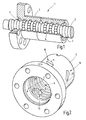
- FIG. 1 shows a ball screw drive 1 is illustrated, a threaded spindle 2 and a threaded nut. 3 having. While the threaded spindle 2 with an external thread 4 provided, the threaded nut 3 with an internal thread 5 provided. The external thread 4 and the internal thread 5 each form a career. Defining the raceways together a helically wound channel in which Balls 6 are arranged.
- the threaded nut 3 is illustrated separately in FIG.
- the internal thread 5 is in the present example a catchy thread.
- a deflection piece 9 is arranged between adjacent turns 7, 8, .
- This serves to implement of balls 6 between the turns 7, 8.
- Further deflecting pieces 11, 12 are at other locations of the thread fifth arranged, also each adjacent turns with each other connect to.
- the deflecting pieces 9, 11, 12 are spaced apart axially and circumferentially Arranged. They each close a recirculating ball (Circulation), which the balls by exactly 360 °, relative to the Longitudinal axis of the spindle nut leads.
- the deflecting pieces 9, 11, 12 are in radial openings 13, 14, 15 used, which is the main body of the threaded nut. 3 penetrate in the radial direction.
- the radial openings 13, 14, 15 are preferably formed as slots.
- the long holes are tilted.
- the longitudinal direction of these slots is preferably about 45 ° to the individual turns inclined.
- the deflecting pieces 9, 11, 12 preferably sit with slight preload, i. low backlash or backlash, in the radial openings 13, 14, 15.
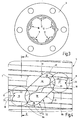
- FIG. 3 illustrates, Not only are the three of Figure 2 apparent Deflecting pieces 9, 11, 12 but, if necessary, more Deflecting pieces 16, 17 distributed around the circumference of the threaded nut 3 arranged. They each protrude over the inner surface the nut 3 inwards in order to with corresponding Sections balls out of the external thread of the threaded spindle 3 record.
- Figure 4 illustrates the same among themselves Deflection pieces 9, 11, 12, 16, 17 based on the example the deflecting piece 9 and the deflection point thus formed between the beginning and the end of the winding 8, which in 4 are designated 8a and 8b.
- the winding 8 has, as shown in particular in FIG. 5 is an ogive profile 18 on. This is too for all other turns, e.g. provided the winding 7.
- the ogival profile 18 forms the track for the load-bearing Area of the internal thread.
- transition profiles 19, 21 are provided, the opposite the pointed arch profile 18 radially outward are deepened.
- the transition profile 19, 21 is as out Figure 5 for the transition profile 19 can be seen, for example a round arch profile. It may, however, if necessary also about another profile, such as a flattened one Act round arch profile or an ogival profile.
- summit this V-shaped edge lies on the apex line 24th of the pointed arch profile 18. This is in particular also off Figure 6 can be seen.
- transition profile 19 or 21 is on Figure 7 referenced.
- the generation is the example of the transition profile 19 illustrated.
- a set up for defined material removal tool 25 such as a side milling cutter or a corresponding shaped grinding wheel, into which of the threaded nut 3 enclosed opening introduced.
- the diameter this tool 25 is smaller than the opening diameter the nut 3.
- the tool 25 is then activated for example, rotated, and on one Track 26 out. This path starts with respect to the axis of rotation 27 of the tool 25 at a position where the outer circumference of the tool 25 with a tangent T the track or the pointed arch profile 18 with an angle of zero or touched a very small acute angle.
- transition profile 19 This one is smaller as the rolling friction angle of the balls. From this point starting, the web 26 runs with a curvature outside, which is smaller than the other curvature of the thread.
- the transition path formed by the transition profile 19 therefore ends at a radius of a few tenths of a millimeter is greater than the radius at the transition point to the support profile 18. It can be straight or, as shown, slightly curved, leaving the tool 25 in course its advancing movement radially outwards into the material the spindle nut 3 is immersed.
- the radial component of motion can be in the range of a few tenths of a millimeter lie. In this way, the transitional profile 19 is created. This connects directly to a bypass channel 28, which is formed in the deflection piece 9.
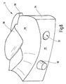
- the deflection piece is preferably constructed in two parts. Its sections 31, 32 are preferably made of plastic and mirror-symmetrical to each other. They adjoin one another at a parting plane 33. This parting plane runs longitudinally through the deflection channel 28.
- the section 31 is illustrated separately in FIG. It has a shaft adjacent to the parting plane 33 34, which is provided with a plane surface 35, the Dividing level 33 determines.
- the plane surface 35 is preferably frusto-conical nubs 36 forth, to corresponding location a complementary shaped recess 37 is assigned.
- the knobs 36 and the recess 37 are arranged and shaped so that two identical sections 31, 32 can be joined to the plane surface 35, wherein the nubs 36 in the recess 37 of the other Section engages and the sections 31, 32 on the deflection channel 28 match each other without offset.
- the dividing level 33 thus creates no level.
- the deflection channel 28 is, as in particular from FIG. 4 emerges, roughly S-shaped wound. He will be at both ends each covered by a pickup 38, the one-piece is formed with the respective section 31, 32 and in the manner of a candy bucket in the thread of the threaded spindle 2 sticks out. It serves to remove the balls from the thread out into the deflection channel 28 to guide.
- a ball screw 1 has a threaded nut 3rd on, which is provided with at least one deflection piece 9, the two ends 8a, 8b of a turn 8 of its internal thread. 5 connects with each other. In the immediate vicinity to the deflection piece 9 are at the ends 8a, 8b of the winding. 8 Transition profiles 19, 21 formed by machine in the Thread are incorporated.
- the transitional profile 19, 21 differs from the supporting profile of the rest of the thread in that the balls, when in the transitional profile 19, 21 are to have some play while within the remaining turn 8 under play Last stand. This is done by changing the profile and / or by a depression of the thread profile radially reached to the outside.
Landscapes
- Engineering & Computer Science (AREA)
- General Engineering & Computer Science (AREA)
- Mechanical Engineering (AREA)
- Transmission Devices (AREA)
Applications Claiming Priority (2)
| Application Number | Priority Date | Filing Date | Title |
|---|---|---|---|
| DE200410004145 DE102004004145B3 (de) | 2004-01-28 | 2004-01-28 | Verfahren zur Herstellung einer Spindelmutter mit Gangumlenkung für einen Kugelgewindetrieb und Kugelgewindetrieb mit Gangumlenkung |
| DE102004004145 | 2004-01-28 |
Publications (2)
| Publication Number | Publication Date |
|---|---|
| EP1559929A2 true EP1559929A2 (fr) | 2005-08-03 |
| EP1559929A3 EP1559929A3 (fr) | 2007-08-01 |
Family
ID=34638765
Family Applications (1)
| Application Number | Title | Priority Date | Filing Date |
|---|---|---|---|
| EP05001415A Withdrawn EP1559929A3 (fr) | 2004-01-28 | 2005-01-25 | Vis à billes avec guide de transfer et son procédé de fabrication |
Country Status (2)
| Country | Link |
|---|---|
| EP (1) | EP1559929A3 (fr) |
| DE (1) | DE102004004145B3 (fr) |
Cited By (5)
| Publication number | Priority date | Publication date | Assignee | Title |
|---|---|---|---|---|
| US7631572B2 (en) * | 2006-11-28 | 2009-12-15 | Showa Corporation | Ball circulating groove structure of ball nut |
| CN104662330B (zh) * | 2013-09-19 | 2017-05-17 | 日本精工株式会社 | 滚珠丝杠 |
| WO2018099516A1 (fr) * | 2016-11-29 | 2018-06-07 | Schaeffler Technologies AG & Co. KG | Écrou fileté pour vis à billes |
| CN113441911A (zh) * | 2021-06-23 | 2021-09-28 | 陕西万方汽车零部件有限公司 | 一种内循环转向螺母一体加工方法 |
| FR3160441A1 (fr) | 2024-03-22 | 2025-09-26 | Ntn Europe | Organe fileté à recirculation et mécanisme de vis à billes |
Families Citing this family (3)
| Publication number | Priority date | Publication date | Assignee | Title |
|---|---|---|---|---|
| DE102011055416B4 (de) | 2011-11-16 | 2022-09-29 | Paul Hettich Gmbh & Co. Kg | Teleskopierbare Hubsäule eines Möbelteils |
| DE102017105732A1 (de) * | 2017-03-17 | 2018-04-26 | Schaeffler Technologies AG & Co. KG | Kugelgewindemutter für einen Kugelgewindetrieb und Verfahren zur Herstellung einer Kugelgewindemutter |
| DE102023107595B4 (de) | 2023-03-27 | 2025-10-02 | Schaeffler Technologies AG & Co. KG | Verfahren zum Herstellen einer Gewindemutter eines Wälzkörpergewindetriebes. |
Family Cites Families (8)
| Publication number | Priority date | Publication date | Assignee | Title |
|---|---|---|---|---|
| US3161073A (en) * | 1961-10-02 | 1964-12-15 | Scully Jones & Co | Ball screw mechanism |
| DE3100349A1 (de) * | 1981-01-08 | 1982-08-05 | Siegmund H. Ing.(grad.) 7440 Nürtingen Kaiser | Kugelgewindetrieb mit interner rohr-umlenkung |
| JP4230020B2 (ja) * | 1998-09-11 | 2009-02-25 | Thk株式会社 | ボールねじナット、該ボールねじナットを使用した直線案内装置及びステアリング用ボールねじ並びにボールねじナットの製造方法 |
| DE10042610B4 (de) * | 1999-09-03 | 2005-01-13 | Nsk Ltd. | "Kugelumlaufspindelvorrichtung" |
| DE19944875A1 (de) * | 1999-09-18 | 2001-03-22 | Schaeffler Waelzlager Ohg | Kugelgewindetrieb |
| JP4729821B2 (ja) * | 2001-08-03 | 2011-07-20 | 日本精工株式会社 | ボールねじ |
| DE10236281A1 (de) * | 2002-08-08 | 2004-02-19 | Ina-Schaeffler Kg | Verfahren zum Herstellen einer Spindelmutter eines Kugelgewindetriebes |
| DE10243020A1 (de) * | 2002-09-17 | 2004-03-25 | Ina-Schaeffler Kg | Kugelgewindetrieb und Verfahren zum Herstellen einer Spindelmutter, insbesondere eines Kugelgewindetriebes |
-
2004
- 2004-01-28 DE DE200410004145 patent/DE102004004145B3/de not_active Expired - Fee Related
-
2005
- 2005-01-25 EP EP05001415A patent/EP1559929A3/fr not_active Withdrawn
Non-Patent Citations (1)
| Title |
|---|
| None |
Cited By (6)
| Publication number | Priority date | Publication date | Assignee | Title |
|---|---|---|---|---|
| US7631572B2 (en) * | 2006-11-28 | 2009-12-15 | Showa Corporation | Ball circulating groove structure of ball nut |
| CN104662330B (zh) * | 2013-09-19 | 2017-05-17 | 日本精工株式会社 | 滚珠丝杠 |
| WO2018099516A1 (fr) * | 2016-11-29 | 2018-06-07 | Schaeffler Technologies AG & Co. KG | Écrou fileté pour vis à billes |
| US11668377B2 (en) | 2016-11-29 | 2023-06-06 | Schaeffler Technologies AG & Co. KG | Threaded nut for a ball screw drive |
| CN113441911A (zh) * | 2021-06-23 | 2021-09-28 | 陕西万方汽车零部件有限公司 | 一种内循环转向螺母一体加工方法 |
| FR3160441A1 (fr) | 2024-03-22 | 2025-09-26 | Ntn Europe | Organe fileté à recirculation et mécanisme de vis à billes |
Also Published As
| Publication number | Publication date |
|---|---|
| EP1559929A3 (fr) | 2007-08-01 |
| DE102004004145B3 (de) | 2005-09-29 |
Similar Documents
| Publication | Publication Date | Title |
|---|---|---|
| DE60007190T2 (de) | Elektrisch angetriebene Lenkeinrichtung | |
| DE3249692C2 (fr) | ||
| DE2805141C2 (de) | Kugelschraubtrieb | |
| DE102012213856B4 (de) | Spindelmutter für einen Kugelgewindetrieb und Elektromechanischer Bremskraftverstärker | |
| DE3032955C2 (de) | Wälzkörperschraubgetriebe | |
| DE19749137B4 (de) | Kugelumlaufspindelvorrichtung des Typs mit eingebettetem Kugelumlaufteil | |
| DE19526727B4 (de) | Kugelumlaufvorrichtung mit externem Umlauf | |
| DE2423299A1 (de) | Mutter fuer kugelumlaufschraubgetriebe | |
| DE2355844A1 (de) | Schraubverbindung | |
| DE102007031078A1 (de) | Drehmomentübertragungseinrichtung, wie Kugelgleichlauffestgelenk als Gegenbahngelenk und Verfahren sowie Werkzeuge zur Herstellung | |
| DE1089607B (de) | Schraubengetriebe | |
| DE10003619A1 (de) | Mutterneinheit | |
| EP0343549B1 (fr) | Boîtier de direction | |
| WO1993006387A1 (fr) | Vis a billes | |
| EP1749158B1 (fr) | Ecrou de vissage pour vis d'entrainement a billes | |
| DE102005061179A1 (de) | Wälzlager und Verfahren zu dessen Herstellung | |
| DE102004004145B3 (de) | Verfahren zur Herstellung einer Spindelmutter mit Gangumlenkung für einen Kugelgewindetrieb und Kugelgewindetrieb mit Gangumlenkung | |
| DE10032578B4 (de) | Getriebeschnecke und Verfahren zum Herstellen einer Getriebeschnecke | |
| DE2833239C2 (de) | Lagerungselement aus nachgiebigem, polymerem Werkstoff | |
| DE102008030100A1 (de) | Gewindefräser | |
| DE19903612A1 (de) | Maschinentisch-Zustellvorrichtung des Einspindeltyps | |
| DE19936837C2 (de) | Mutter für Kugelumlaufgewinde | |
| EP0852168A1 (fr) | Fraise à fileter | |
| EP4025369B1 (fr) | Procédé pour générer un trou taraudé dans une pièce | |
| DE102012212311B4 (de) | Planetengewindetrieb mit Schmiermittelverteilausnehmung |
Legal Events
| Date | Code | Title | Description |
|---|---|---|---|
| PUAI | Public reference made under article 153(3) epc to a published international application that has entered the european phase |
Free format text: ORIGINAL CODE: 0009012 |
|
| AK | Designated contracting states |
Kind code of ref document: A2 Designated state(s): AT BE BG CH CY CZ DE DK EE ES FI FR GB GR HU IE IS IT LI LT LU MC NL PL PT RO SE SI SK TR |
|
| AX | Request for extension of the european patent |
Extension state: AL BA HR LV MK YU |
|
| PUAL | Search report despatched |
Free format text: ORIGINAL CODE: 0009013 |
|
| AK | Designated contracting states |
Kind code of ref document: A3 Designated state(s): AT BE BG CH CY CZ DE DK EE ES FI FR GB GR HU IE IS IT LI LT LU MC NL PL PT RO SE SI SK TR |
|
| AX | Request for extension of the european patent |
Extension state: AL BA HR LV MK YU |
|
| 17P | Request for examination filed |
Effective date: 20070815 |
|
| 17Q | First examination report despatched |
Effective date: 20071017 |
|
| AKX | Designation fees paid |
Designated state(s): AT BE BG CH CY CZ DE DK EE ES FI FR GB GR HU IE IS IT LI LT LU MC NL PL PT RO SE SI SK TR |
|
| STAA | Information on the status of an ep patent application or granted ep patent |
Free format text: STATUS: THE APPLICATION IS DEEMED TO BE WITHDRAWN |
|
| 18D | Application deemed to be withdrawn |
Effective date: 20080429 |