EP1559997B1 - Niveau à bulle - Google Patents
Niveau à bulle Download PDFInfo
- Publication number
- EP1559997B1 EP1559997B1 EP04029421A EP04029421A EP1559997B1 EP 1559997 B1 EP1559997 B1 EP 1559997B1 EP 04029421 A EP04029421 A EP 04029421A EP 04029421 A EP04029421 A EP 04029421A EP 1559997 B1 EP1559997 B1 EP 1559997B1
- Authority
- EP
- European Patent Office
- Prior art keywords
- level
- spirit
- mounting
- clamping part
- holding apparatus
- Prior art date
- Legal status (The legal status is an assumption and is not a legal conclusion. Google has not performed a legal analysis and makes no representation as to the accuracy of the status listed.)
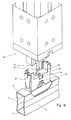
- Expired - Lifetime
Links
- 238000000034 method Methods 0.000 claims abstract 4
- 238000005259 measurement Methods 0.000 claims description 12
- 238000003780 insertion Methods 0.000 claims description 3
- 230000037431 insertion Effects 0.000 claims description 3
- 238000006073 displacement reaction Methods 0.000 claims description 2
- 241000238633 Odonata Species 0.000 description 20
- 238000001514 detection method Methods 0.000 description 9
- 210000003128 head Anatomy 0.000 description 4
- 238000009434 installation Methods 0.000 description 3
- 238000013461 design Methods 0.000 description 2
- 210000001331 nose Anatomy 0.000 description 2
- 230000004308 accommodation Effects 0.000 description 1
- 230000015572 biosynthetic process Effects 0.000 description 1
- 230000003750 conditioning effect Effects 0.000 description 1
- 210000003746 feather Anatomy 0.000 description 1
- 238000007373 indentation Methods 0.000 description 1
- 239000007788 liquid Substances 0.000 description 1
- 238000012986 modification Methods 0.000 description 1
- 230000004048 modification Effects 0.000 description 1
- 238000012549 training Methods 0.000 description 1
- 230000007704 transition Effects 0.000 description 1
- 210000003462 vein Anatomy 0.000 description 1
- XLYOFNOQVPJJNP-UHFFFAOYSA-N water Substances O XLYOFNOQVPJJNP-UHFFFAOYSA-N 0.000 description 1
Images


Classifications
-
- G—PHYSICS
- G01—MEASURING; TESTING
- G01C—MEASURING DISTANCES, LEVELS OR BEARINGS; SURVEYING; NAVIGATION; GYROSCOPIC INSTRUMENTS; PHOTOGRAMMETRY OR VIDEOGRAMMETRY
- G01C9/00—Measuring inclination, e.g. by clinometers, by levels
- G01C9/18—Measuring inclination, e.g. by clinometers, by levels by using liquids
- G01C9/24—Measuring inclination, e.g. by clinometers, by levels by using liquids in closed containers partially filled with liquid so as to leave a gas bubble
- G01C9/26—Details
- G01C9/28—Mountings
-
- G—PHYSICS
- G01—MEASURING; TESTING
- G01C—MEASURING DISTANCES, LEVELS OR BEARINGS; SURVEYING; NAVIGATION; GYROSCOPIC INSTRUMENTS; PHOTOGRAMMETRY OR VIDEOGRAMMETRY
- G01C25/00—Manufacturing, calibrating, cleaning, or repairing instruments or devices referred to in the other groups of this subclass
Definitions
- the invention relates to a spirit level with a consisting of a hollow profile spirit level body having a bottom wall whose underside forms a measuring surface, a top wall and the bottom wall and the top wall connecting side walls, and having a horizontal vial for a horizontal measurement, which is arranged in a window recess of the spirit level body is and is fixed in the spirit level body by means of a holding device, which has a dragonfly socket, in which the horizontal vial is fixed, and at least one clamping part, which is displaceable for clamping the holding device in spirit level body relative to the level detection.
- a spirit level of the type mentioned is from the DE 36 06 774 C2 known.
- the dragonfly socket has expansion cams, which cooperate with expansion bodies, which form clamping parts. By moving the spreader, starting from its passive position in its active position, the expansion cams are pressed against the inner sides of the side walls of the spirit level body, whereby the holding device for the horizontal vial is braced in spirit level body.
- the DE 36 06 774 C2 a simple installation of the holder for the horizontal vial in spirit level body, however, it has been shown that in temperature fluctuations, the adjustment of the vial relative to the measuring surface of the spirit level body is not optimally maintained. Also, tolerances of the profile cross section of the spirit level body and the parts of the holding device can only be taken very limited.
- the object of the invention is to provide a spirit level, in the temperature fluctuations affect the accuracy of the horizontal vein as little as possible. According to the invention, this is achieved by a spirit level with the features of patent claim 1.
- the at least one clamping part presses the level of the dragonfly on the inside of the bottom wall, the underside forms the measuring surface, despite varying coefficients of expansion of the various parts (spirit level body, level detection, clamping part and dragonfly), the influence on the accuracy of measurement can be kept extremely small.
- Different expansion values of water body, level detection and clamping part can be compensated advantageously by an elastically bendable design of the clamping part.
- cross-sectional tolerances of the spirit-level body and tolerances of the built-in parts (level detection and clamping part) can be advantageously absorbed by an elastically bendable design of the clamping part.
- the clamping part is formed as a U-shaped bracket and has two arms connected via a connecting leg, whose ends remote from the connecting leg are supported on both sides (based on the longitudinal extent of the spirit level body) of the window opening on the inside of the top wall.
- the connecting leg can in this case be connected in the mounted state of the holding device with the level of dragonflies (for example, by a snap connection) and be elastically bent, wherein it exerts a pressing force on the level detection, with which it is pressed against the bottom wall of the spirit level body.
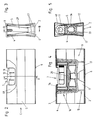
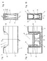
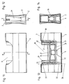
- FIGS. 1 to 15 A first embodiment of the invention is shown in FIGS. 1 to 15.
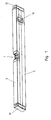
- the spirit level has a spirit level body 1, which is formed by a hollow profile, which has a bottom wall 2, a top wall 3 and side walls 4, 5, which connect the bottom wall and the top wall together.
- the bottom of the bottom wall 2 forms a measuring surface 6.
- the spirit level has to carry out a horizontal measurement, a horizontal vial 7, which is arranged in a window recess 8 of the spirit level body 1, for which purpose a holding device 9 is used.
- the spirit level further has to carry out a vertical measurement a vertical vial 10. This is also set in a window recess in the spirit level body by means of a holding device.
- This holding device of the vertical vial is irrelevant in connection with the present invention and therefore need not be explained further.
- This holding device for the vertical vial can in conventional Be formed manner. In principle, a vertical vial could also be omitted.
- end caps 50 may be inserted in the ends of the spirit level body 1 in the ends of the spirit level body 1 in the ends of the spirit level body 1 end caps 50 may be inserted.
- the horizontal vial 7 may be formed in a conventional manner and have a vial body 11 with a barrel-shaped cavity into which a vial liquid containing a bubble 12 is filled. To mark the horizontal position of the dragonfly body 11 is provided with marking rings 13. The vial body 11 is glued into a frame 14 which surrounds this end face and on the underside, which is thus U-shaped in a side view.
- the vial body 11 is formed in the embodiment shown as a so-called relatively thick-walled "block vial” in which the vial body is first injected with a cylindrical or to its opening side (which is closed later) slightly conical cavity, which is turned out barrel-shaped in the episode.
- a training as a so-called “dragonfly” would be conceivable and possible, in which a relatively thin-walled dragonfly body is injected from the outset with a barrel-shaped cavity and forced demoulded.
- the holding device 9 for the horizontal vial 7 comprises a vial holder 15 and a clamping part 16.
- the vial holder 15 has support legs 17, the free ends of which are pressed in the assembled state of the holding device 9 to the inside of the bottom wall 2.
- the dragonfly socket 15 has a receiving space 18 for the horizontal vial 7. This is bounded by a bottom part 19 and on the longitudinal direction of the spirit level at both ends of the bottom part 19 mounted frontal parts 20, 21.
- At the side edges of the frontal parts 20, 21 are respectively from flange webs 22, which overlap vertical portions of the frame 14 in the inserted state of the horizontal vial.
- the two support feet 17 on a respective longitudinal side of the dragonfly socket 15 are connected to each other by a bridge portion 23, in which first and second recesses 24, 25 are arranged.
- bottom part 19 further comprises a through hole 26 and a transverse groove 27 are formed.
- this groove 27 is in the mounted state of the horizontal vial 7, a pivot web 28 which is formed on the underside of the frame 14, wherein the height of the pivot web 28 is greater than the depth of the groove 27.
- the clamping part 16 is formed as seen in side view U-shaped bracket and has two arms 29, 30, which in the assembled state of the holding device 9 with a normal 31st on the measuring surface 6 include an angle 32 of less than 45 °, said angle 32 is preferably less than 20 °, with a value of less than 10 ° is particularly preferred.
- the arms 29, 30 are interconnected by a connecting leg 33 running in the longitudinal direction of the spirit level body 1. At their remote from the connecting leg 33 free ends 34, 35, the arms 29, 30 are supported in the assembled state of the holding device 9 on the inside of the top wall 3 from.
- two hook parts 36 are arranged in the illustrated embodiment in the central region of its longitudinal extent.
- the two hook parts 36 are snapped into the two first recesses 24 of the bridge sections 23.
- the hook portions 36 are snapped into the second recesses 25, said second recesses 25 have a smaller height than the first recesses 24 so that the hook parts 36 can not snap over the entire length I (shown in FIG. 6) of their wedge-shaped latching noses but only over part of their length I (see, for example, FIG.
- the connecting leg 33 is elastically bendable and elastically bent in the assembled state of the holding device 9, as is apparent from FIGS. 4 and 13.
- the connecting leg 33 is located between the arranged on the two longitudinal sides of the bottom part 19 support legs 17.
- the arms 29, 30 extend in vertical longitudinal section (Fig. 4 and 13) seen on both sides of the level detection.
- Further guide bevels 37, 38 are arranged on the end-face parts 20, 21 of the leveling frame 15, which interact with the arms 29, 30 and which, when the tensioning part 16 is displaced into the mounted position of the holding device 9, the free ends 34, 35 of the arms 29, 30 slightly deflect in the direction of the front ends 39, 40 of the spirit level body 1 to bring the free ends 34, 35 of the arms 29, 30 on the top wall 3 in areas laterally of the window recess 8 for conditioning.
- the guide slopes 37, 38 are attached to the mutually remote outer sides of the frontal parts 20, 22, in the region of their ends remote from the bottom part 19.
- the connecting leg 33 has a passage opening 43, which is aligned in the assembled state of the holding device 9 with the passage opening 26 in the bottom part 19.
- the clamping part 16 is inserted with its hook parts 36 in the second recesses 25, as shown in Fig. 15.
- the so interconnected parts 15, 16 are inserted into the window recess 8 until the support legs 17 of the level bracket 15 rise on the bottom wall 2 (see Fig .. 7 to 10).
- the clamping part 16 is pulled in the direction of the top wall 3 until the hook parts 36 engage in the first recesses 24.
- the clamping member 16 is supported thereafter with the free ends 34, 35 of its arms 29, 30 on the inside of the top wall 3 and is elastically tensioned, whereby it presses the dragonfly socket 15 against the bottom wall 2.
- the holding device 9 is thus clamped between the top wall 3 and the bottom wall 2 (cf., FIGS. 11 to 14).
- the horizontal vial 7 is inserted into the receiving space 18 of the dragonfly socket 15, wherein it is rocker-like about the support line or partially cylindrical bearing surface of the pivot web 28 in the groove 27 is pivotable.
- the horizontal vial 7 is set in the vial holder 15 by making a rigid connection between these two parts, for example glued or welded.
- a cover 49 is attached and possibly glued, which covers the transition region between the Horizontalallelle 7 and the edge of the window recess 8.
- FIG. 15 An assembly tool 44 for mounting the level detection is shown in Fig. 15 by way of example.
- the shaft 45 In a rotational position of the shaft 45, which is shown in Fig. 15, the head 46 through the through holes 26, 43 in the bottom part 19 and in the Connecting leg 33 feasible.
- the shaft 45 is rotated by 90 ° about its longitudinal axis, so that the head 46 engages behind the edge of the through hole 43 in the connecting leg 33.
- the shaft 45 is retracted axially (so that the head 46 moves in the direction of the top wall 3) until the hook parts 36 engage in the first latching recesses 24.
- FIG. 1 For bracing the holder 9 in spirit level body 1 here is a clamping screw 47 is present.
- the clamping screw 47 By means of the clamping screw 47, the clamping part 16 after insertion of the holding device in the window recess 8 is displaced in the direction of the top wall 3 and under the support of the free ends of its arms 29, 30 stretched on the inside of the top wall 3, whereby the dragonfly socket 15 is pressed against the bottom wall 2.
- FIG. 17 shows a further exemplary embodiment of the invention.
- a spring 48 acting between the bottom part 19 of the level detection frame 15 and the connecting leg 33 of the tensioning part 16 is present, which is designed here as a tension spring.
- the spring 48 is stretched so far that the free ends of the arms 29, 30 are below the guide slopes 37, 38.
- a suitable tool can be used which distances the connecting leg 33 correspondingly far from the bottom part 19.
- the tool After insertion into the window recess 8, the tool releases the parts, causing the spring 48 pulls the connecting leg 33 in the direction of the top wall, so that the free ends of the arms 29, 30 are pressed under bias of the spring 48 to the inside of the top wall 3 and the dragonfly socket 15 is pressed in response to the bottom wall 2.
- the clamping member 16 and the connecting leg 33 of the clamping member 16 may be formed inelastic in this embodiment.
- the clamping part 16 is displaceable parallel to the normal 31 on the measuring surface 6 with respect to the level of dragonflies 15. Also, a displacement at an angle to the normal 31 would be conceivable and possible, this angle is preferably less than 45 °.
Landscapes
- Engineering & Computer Science (AREA)
- Physics & Mathematics (AREA)
- General Physics & Mathematics (AREA)
- Radar, Positioning & Navigation (AREA)
- Remote Sensing (AREA)
- Manufacturing & Machinery (AREA)
- Medical Preparation Storing Or Oral Administration Devices (AREA)
- Details Of Rigid Or Semi-Rigid Containers (AREA)
- Measurement Of Levels Of Liquids Or Fluent Solid Materials (AREA)
- Control Of Motors That Do Not Use Commutators (AREA)
- Clamps And Clips (AREA)
- Sampling And Sample Adjustment (AREA)
- Force Measurement Appropriate To Specific Purposes (AREA)
Claims (19)
- Niveau à bulle comportant un corps formé d'un profil creux ayant un fond (2) dont la face inférieure constitue une surface de mesure (6), une paroi supérieure (3) et des parois latérales (4, 5) reliant le fond (2) et la paroi supérieure (3) ainsi qu'une cellule horizontale (7) pour mesurer le niveau horizontal, cette cellule étant logée dans un encadrement de fenêtre (8) du corps (1) du niveau en étant fixé par un dispositif de retenue (9) dans le corps (1), ce dispositif de retenue est enserré dans le corps (1) et il fixe un entourage de cellule (15) dans lequel est bloqué la cellule horizontale (7) et au moins une pièce de serrage (16) coulissant par rapport à l'encadrement de cellule (15) pour serrer le dispositif de retenue (9) dans le corps (1) du niveau,
au moins l'unique pièce de serrage (16) coulisse dans une direction par rapport à l'encadrement de cellule (15) qui fait un angle inférieur à 45° par rapport à la normale (31) à la surface de mesure (6)
caractérisé en ce que
à l'état serré du dispositif de fixation (9) au moins l'unique pièce de serrage (16) s'appuie contre le côté intérieur de la paroi supérieure (3) et pousse l'encadrement de cellule (15) par la pièce de serrage (16) contre le côté intérieur du fond (2). - Niveau à bulle selon la revendication 1,
caractérisé en ce que
la pièce de serrage (16) comporte deux bras (29, 30) qui font entre eux un angle et sont reliés par une branche de liaison (33)
les extrémités (34, 35) non situées du côté de la branche de liaison (33) s'appuient de part et d'autre de la cavité de fenêtre (8) contre le côté intérieur de la paroi supérieure (3) lorsqu'on regarde le corps (1) du niveau à bulle en coupe verticale longitudinale. - Niveau à bulle selon la revendication 2,
caractérisé en ce que
les bras (29, 30) s'étendent de part et d'autre de l'encadrement de cellule (15) pour une coupe longitudinale verticale du corps de niveau (1). - Niveau à bulle selon la revendication 2 ou la revendication 3,
caractérisé en ce que
la branche de liaison (33) se situe entre les pieds (17) de l'encadrement de cellule (15) qui viennent dans une section du corps du niveau (1), lorsqu'on regarde de part et d'autre de la branche de liaison (33) et dont les extrémités libres sont poussées contre le côté intérieur du fond (2). - Niveau à bulle selon l'une des revendications 1 à 4,
caractérisé en ce qu'
à l'état serré du dispositif de fixation (9) au moins une pièce de serrage (16) est accrochée par une liaison par enclipsage à l'encadrement de cellule (15). - Niveau à bulle selon l'une des revendications 2 à 5,
caractérisé en ce que
la branche de liaison (33) comporte de préférence dans sa zone médiane de sa longueur, au moins une pièce formant crochet (36), qui à l'état tendu du dispositif de retenue, est enclipsée dans une cavité d'enclipsage (24) de l'encadrement de cellule (15). - Niveau à bulle selon la revendication 6
caractérisé en ce qu'
en vue en coupe du corps de niveau, sur les grands côtés opposés de la branche de liaison (33) il y a des pièces formant crochet (36) enclipsées dans les cavités d'enclipsage (34). - Niveau à bulle selon la revendication 6 ou la revendication 7,
caractérisé en ce que
pour chaque pièce en forme de crochet (36), en plus d'une première cavité d'enclipsage (24), il y a une seconde cavité d'enclipsage (25) de l'encadrement de cellule (15) dans laquelle s'accroche la pièce en forme de crochet (36) en position de pré-enclipsage de la pièce de serrage (16) lorsqu'on place le dispositif de retenue (9) dans la cavité de fenêtre (8). - Niveau à bulle selon l'une des revendications 1 à 5,
caractérisé en ce que
pour serrer le dispositif de fixation (9) dans le corps (1) du niveau, il est prévu au moins une vis de serrage (47) coopérant entre l'encadrement de cellule (15) et au moins la pièce de serrage (16). - Niveau à bulle selon l'une des revendications 1 à 5,
caractérisé en ce que
pour serrer le dispositif de fixation (9), le corps (1) du niveau comporte au moins un ressort (48) agissant entre l'encadrement de niveau (15) et au moins une pièce de serrage (16). - Niveau à bulle selon l'une des revendications 1 à 10,
caractérisé en ce qu'
au moins la pièce de serrage (16) peut coulisser dans une direction parallèle à la normale (31) à la surface de mesure (6). - Niveau à bulle selon l'une des revendications 2 à 11,
caractérisé en ce que
l'encadrement de cellule (15) comporte des rampes de guidage (37, 38) coopérant avec les bras (29, 30) de la pièce de serrage (16), au coulissement de la pièce de serrage (16) en direction de la paroi supérieure (3), ces rampes écartent les extrémités libres (34, 35) des bras (29,30) pour leur appui contre les zones du plafond (13) situés à côté de la cavité de fenêtre (8), en direction des extrémités côté frontal (39, 40) du corps de cellule (1). - Niveau à bulle selon la revendication 12,
caractérisé en ce que
la rampe de guidage comporte sur les côtés extérieurs non tournés l'un vers l'autre, deux pièces, côté frontal (20, 21) de l'encadrement de cellule (15), au niveau des extrémités tournées vers la paroi supérieure (3), des pièces (20, 21) dont la face frontale est tournée vers ces extrémités. - Niveau à bulle selon l'une des revendications 1 à 13,
caractérisé en ce que
l'encadrement de cellule (15) comporte un logement (18) pour la cellule horizontale (7) qui est délimite en direction de la paroi du fond (2) du corps de niveau par une partie de fond (19) et en direction des extrémités (39, 40) côté frontal du corps (1) de niveau, par des parties frontales (20, 21). - Niveau à bulle selon la revendication 4,
caractérisé en ce que
les pieds (17) de l'encadrement de cellule (15) sont en saillie de la partie de fond (19) en direction du fond (2) du corps de niveau, et de préférence les deux bords côté longitudinal de la partie de fond (19) comportent des pieds d'appui (17). - Niveau à bulle selon l'une des revendications 2 à 15,
caractérisé en ce que
la branche de liaison (33) est déformable élastiquement et elle est cintrée élastiquement à l'état tendu du dispositif de fixation (9). - Procédé de montage d'une cellule horizontale (7) dans une cavité de fenêtre (8) d'un corps (1) de niveau à bulle, formé par un profil creux et ayant un fond (2) dont la face inférieure constitue une surface de mesure (6), une paroi supérieure (3) et des parois latérales (4, 5) reliant le fond (2) et la paroi supérieure (3), un dispositif de retenue (9), ayant un encadrement de cellule (15) auquel est fixé la cellule horizontale (7) et au moins une pièce de serrage (16) est logée dans la cavité de fenêtre (8) du corps de niveau (1) et ensuite on coulisse au moins la pièce de serrage (16) par rapport à l'encadrement de cellule (15) dans une direction faisant avec une normale (31) et la surface de mesure (6), un angle inférieur à 45°, pour bloquer ainsi le dispositif de retenue (9) dans le corps de niveau (1),
caractérisé en ce que
pour serrer le dispositif de retenue (9) dans le corps de niveau (1), la pièce de serrage (16) est coulissée d'une position écartée de la paroi supérieure (3) dans une position appliquée contre le côté intérieur de la paroi supérieure (3),
l'encadrement de cellule (15) étant poussé contre le côté intérieur du fond (2) par la pièce de serrage (16) qui s'appuie contre la paroi supérieure (3) et le dispositif de retenue (9) est tendu entre la paroi supérieure (3) et le fond (2). - Procédé selon la revendication 17,
caractérisé en ce qu'
on accroche l'un à l'autre une pièce de serrage (16) et un encadrement de cellule (15) pour réaliser le serrage entre la paroi supérieure (3) et le fond (2). - procédé selon la revendication 18,
caractérisé en ce que
l'encadrement de cellule (15) et au moins une pièce de serrage (16) sont placés à l'état pré-engagé dans la cavité de fenêtre (8) et ensuite, à l'aide d'un outil de montage (44) ayant une tête (46) sur une tige (45) réglable dans la direction axiale et pivotant autour de son axe longitudinal, par passage de la tête (46) à travers des orifices de passage (26) dans l'encadrement de cellule (15) et des orifices de passage (43) dans la partie de serrage (16) puis prise par derrière des bords de l'orifice de passage (43), dans la pièce de serrage (16) en tournant l'axe (45) autour de son axe géométrique longitudinal et ensuite en retirant la tête (46) on bloque et le blocage reste maintenu.
Applications Claiming Priority (2)
| Application Number | Priority Date | Filing Date | Title |
|---|---|---|---|
| AT1122004 | 2004-01-28 | ||
| AT0011204A AT414044B (de) | 2004-01-28 | 2004-01-28 | Wasserwaage |
Publications (2)
| Publication Number | Publication Date |
|---|---|
| EP1559997A1 EP1559997A1 (fr) | 2005-08-03 |
| EP1559997B1 true EP1559997B1 (fr) | 2008-01-23 |
Family
ID=34637609
Family Applications (1)
| Application Number | Title | Priority Date | Filing Date |
|---|---|---|---|
| EP04029421A Expired - Lifetime EP1559997B1 (fr) | 2004-01-28 | 2004-12-13 | Niveau à bulle |
Country Status (6)
| Country | Link |
|---|---|
| US (1) | US7765706B2 (fr) |
| EP (1) | EP1559997B1 (fr) |
| CN (1) | CN100554881C (fr) |
| AT (2) | AT414044B (fr) |
| DE (1) | DE502004006038D1 (fr) |
| ES (1) | ES2300698T3 (fr) |
Families Citing this family (25)
| Publication number | Priority date | Publication date | Assignee | Title |
|---|---|---|---|---|
| IL149274A0 (en) * | 2002-04-22 | 2002-11-10 | Kapro Ind Ltd | Bubble vial assembly and method therefor |
| JP4275112B2 (ja) * | 2005-07-20 | 2009-06-10 | 株式会社エビス | 水準器 |
| US7464479B2 (en) * | 2006-05-18 | 2008-12-16 | The Stanley Works | Level vial and manufacturing method therefor |
| US7472486B2 (en) * | 2006-05-19 | 2009-01-06 | The Stanley Works | Level with vial and manufacturing method therefor |
| US7472487B2 (en) | 2006-05-26 | 2009-01-06 | The Stanley Works | Level |
| US7832112B2 (en) * | 2008-11-10 | 2010-11-16 | Empire Level Mfg. Co. | Vial-mounting structure |
| GB2541819B (en) * | 2009-10-29 | 2017-07-05 | Empire Level Mfg Corp | Box level |
| AU2015261620B2 (en) * | 2009-10-29 | 2017-01-12 | Empire Level Mfg. Corp. | Box level |
| AT509146B1 (de) | 2009-11-16 | 2011-10-15 | Sola Messwerkzeuge Gmbh | Wasserwaage |
| CA2797106C (fr) * | 2010-05-03 | 2016-11-08 | James S. Allemand | Niveau eclaire |
| CN102445215B (zh) * | 2011-09-26 | 2013-06-12 | 中国航空工业第六一八研究所 | 用于挠性陀螺信号器测试的升降装置 |
| US8914987B2 (en) | 2012-01-31 | 2014-12-23 | Stanley Black & Decker, Inc. | I-beam level |
| US9625260B2 (en) | 2014-04-16 | 2017-04-18 | Stanley Black & Decker, Inc. | Carbon fiber composite level and method of manufacturing same |
| WO2016077737A1 (fr) | 2014-11-13 | 2016-05-19 | Milwaukee Electric Tool Corporation | Niveau comprenant des couvercles d'extrémité amovibles |
| AT517233B1 (de) | 2015-07-07 | 2016-12-15 | Sola-Messwerkzeuge Gmbh | Wasserwaage |
| TWM523092U (zh) * | 2015-11-09 | 2016-06-01 | Woodson Company Ltd | 水平尺改良結構 |
| US20170343347A1 (en) * | 2016-05-26 | 2017-11-30 | Ching Lin Plastic Industry Co., Ltd. | Easy assembly level |
| WO2018119075A1 (fr) * | 2016-12-21 | 2018-06-28 | Milwaukee Electric Tool Corporation | Niveau à capuchon d'extrémité amovible |
| US10845193B2 (en) | 2016-12-21 | 2020-11-24 | Milwaukee Electric Tool Corporation | Level with removable end cap |
| CN111989542B (zh) | 2018-04-27 | 2022-10-25 | 米沃奇电动工具公司 | 具有带有壁卡持部的可移除端盖的水平仪 |
| US11085762B2 (en) | 2018-04-27 | 2021-08-10 | Milwaukee Electric Tool Corporation | Level with removable end cap with wall grip |
| US11193764B2 (en) | 2019-01-17 | 2021-12-07 | Milwaukee Electric Tool Corporation | Two datum vial mounting system and method |
| WO2020150484A1 (fr) | 2019-01-17 | 2020-07-23 | Milwaukee Electric Tool Corporation | Système et procédé de montage de flacons à deux repères |
| US10928197B2 (en) * | 2019-02-07 | 2021-02-23 | Diamond Tech LLC | Level vial mounting system for a box beam level |
| CN116295534B (zh) * | 2023-04-23 | 2023-08-18 | 河北省科学院应用数学研究所 | 水准泡温漂检测方法及系统 |
Family Cites Families (10)
| Publication number | Priority date | Publication date | Assignee | Title |
|---|---|---|---|---|
| US1393328A (en) * | 1920-03-25 | 1921-10-11 | Fred Ohde | Level device |
| US1624161A (en) * | 1926-03-01 | 1927-04-12 | Day Jacob | Spirit level |
| DE3127399A1 (de) * | 1981-07-10 | 1983-01-27 | Stabila-Messgeräte Gustav Ullrich GmbH & Co KG, 6747 Annweiler | Wasserwaage |
| DE3432911A1 (de) * | 1984-09-07 | 1986-03-20 | Scheyer, Guido, Ing., Götzis | Wasserwaage |
| DE3606774A1 (de) * | 1986-03-01 | 1987-09-03 | Keller Bayer Mass Ind | Vorrichtung zum befestigen der libelle einer wasserwaage |
| CH690200A5 (de) * | 1995-09-29 | 2000-05-31 | Mapo Ag | Wasserwaage mit Magnethaftung |
| JP3748681B2 (ja) * | 1997-08-29 | 2006-02-22 | 株式会社ガスター | 一缶二水路風呂給湯器 |
| JP3754537B2 (ja) * | 1997-09-17 | 2006-03-15 | 株式会社ガスター | 一缶二水路給湯器 |
| JP3073950B2 (ja) * | 1997-12-24 | 2000-08-07 | 株式会社エビス | 水準器 |
| JP3073951B2 (ja) * | 1997-12-25 | 2000-08-07 | 株式会社エビス | 水準器 |
-
2004
- 2004-01-28 AT AT0011204A patent/AT414044B/de not_active IP Right Cessation
- 2004-12-13 EP EP04029421A patent/EP1559997B1/fr not_active Expired - Lifetime
- 2004-12-13 DE DE502004006038T patent/DE502004006038D1/de not_active Expired - Lifetime
- 2004-12-13 ES ES04029421T patent/ES2300698T3/es not_active Expired - Lifetime
- 2004-12-13 AT AT04029421T patent/ATE384932T1/de active
-
2005
- 2005-01-26 US US11/043,421 patent/US7765706B2/en not_active Expired - Fee Related
- 2005-01-27 CN CNB2005100677338A patent/CN100554881C/zh not_active Expired - Fee Related
Also Published As
| Publication number | Publication date |
|---|---|
| DE502004006038D1 (de) | 2008-03-13 |
| ATE384932T1 (de) | 2008-02-15 |
| EP1559997A1 (fr) | 2005-08-03 |
| US20050160610A1 (en) | 2005-07-28 |
| AT414044B (de) | 2006-08-15 |
| ES2300698T3 (es) | 2008-06-16 |
| CN1664503A (zh) | 2005-09-07 |
| US7765706B2 (en) | 2010-08-03 |
| CN100554881C (zh) | 2009-10-28 |
| ATA1122004A (de) | 2005-11-15 |
Similar Documents
| Publication | Publication Date | Title |
|---|---|---|
| EP1559997B1 (fr) | Niveau à bulle | |
| DE102013112645B3 (de) | Türband | |
| EP0226785A2 (fr) | Renvoi d'angle pour tringles d'immobilisation d'une fenêtre ou porte | |
| DE2630763B2 (de) | Haltevorrichtung für teleskopartig ineinander verschiebbare Stangen mit ähnlichem Querschnitt | |
| DE2342113A1 (de) | Moebelscharnier mit verstellbarem scharnierarm | |
| DE19901775A1 (de) | T-Verbindung zwischen einem Sprossen- und einem Pfostenprofil einer Fassade oder eines Lichtdaches | |
| DE202005015034U1 (de) | Gleitstück für einen Beschlag | |
| DE19828382C2 (de) | Anordnung zum Befestigen eines einen Hohlquerschnitt aufweisenden Pfostens am Blendrahmen eines Fensters oder einer Türe aus Kunststoff oder Leichtmetall | |
| EP0010260B1 (fr) | Serre-joints | |
| DE3326763A1 (de) | Tuerband | |
| DE60011949T2 (de) | Verriegelungsbeschlag vom Typ Treibstangenbeschlag oder dergleichen | |
| EP0529229A1 (fr) | Chevilles murales | |
| DE4345103C2 (de) | Vorrichtung zur Befestigung von winkeligen Installationselementen | |
| DE3147306C2 (de) | Leiter | |
| EP0039467A2 (fr) | Pièce d'écartement | |
| DE3129851C2 (de) | Mehrteiliger Möbelfuß aus Kunststoff | |
| DE3728759C2 (fr) | ||
| CH690132A5 (de) | Entwässerungsrinne. | |
| DE3308812A1 (de) | Trag- und laufrollenvorrichtung fuer schiebetueren | |
| DE2509071C2 (de) | Markisenkasten mit Lager für eine Tuchrolle | |
| WO2003046323A1 (fr) | Element de maintien, procede de production d'un element de maintien et utilisation d'elements extrudes | |
| DE10114083C1 (de) | Stoßverbindung eines Kämpferhohlprofils mit einem Rahmen- oder Sprossenprofil | |
| EP1318378A1 (fr) | Niveau à bulle à profil creux | |
| AT326299B (de) | Festhalter zum fixieren von in einer innenläuferschiene geführten tragkorpern für vorhänge od.dgl. | |
| EP4379176A2 (fr) | Support de charnière |
Legal Events
| Date | Code | Title | Description |
|---|---|---|---|
| PUAI | Public reference made under article 153(3) epc to a published international application that has entered the european phase |
Free format text: ORIGINAL CODE: 0009012 |
|
| AK | Designated contracting states |
Kind code of ref document: A1 Designated state(s): AT BE BG CH CY CZ DE DK EE ES FI FR GB GR HU IE IS IT LI LT LU MC NL PL PT RO SE SI SK TR |
|
| AX | Request for extension of the european patent |
Extension state: AL BA HR LV MK YU |
|
| 17P | Request for examination filed |
Effective date: 20060114 |
|
| AKX | Designation fees paid |
Designated state(s): AT BE BG CH CY CZ DE DK EE ES FI FR GB GR HU IE IS IT LI LT LU MC NL PL PT RO SE SI SK TR |
|
| GRAP | Despatch of communication of intention to grant a patent |
Free format text: ORIGINAL CODE: EPIDOSNIGR1 |
|
| GRAS | Grant fee paid |
Free format text: ORIGINAL CODE: EPIDOSNIGR3 |
|
| GRAA | (expected) grant |
Free format text: ORIGINAL CODE: 0009210 |
|
| AK | Designated contracting states |
Kind code of ref document: B1 Designated state(s): AT BE BG CH CY CZ DE DK EE ES FI FR GB GR HU IE IS IT LI LT LU MC NL PL PT RO SE SI SK TR |
|
| REG | Reference to a national code |
Ref country code: GB Ref legal event code: FG4D Free format text: NOT ENGLISH |
|
| REG | Reference to a national code |
Ref country code: CH Ref legal event code: EP |
|
| REG | Reference to a national code |
Ref country code: IE Ref legal event code: FG4D Free format text: LANGUAGE OF EP DOCUMENT: GERMAN |
|
| REF | Corresponds to: |
Ref document number: 502004006038 Country of ref document: DE Date of ref document: 20080313 Kind code of ref document: P |
|
| REG | Reference to a national code |
Ref country code: CH Ref legal event code: NV Representative=s name: LUCHS & PARTNER PATENTANWAELTE |
|
| REG | Reference to a national code |
Ref country code: SE Ref legal event code: TRGR |
|
| REG | Reference to a national code |
Ref country code: ES Ref legal event code: FG2A Ref document number: 2300698 Country of ref document: ES Kind code of ref document: T3 |
|
| NLV1 | Nl: lapsed or annulled due to failure to fulfill the requirements of art. 29p and 29m of the patents act | ||
| PG25 | Lapsed in a contracting state [announced via postgrant information from national office to epo] |
Ref country code: IS Free format text: LAPSE BECAUSE OF FAILURE TO SUBMIT A TRANSLATION OF THE DESCRIPTION OR TO PAY THE FEE WITHIN THE PRESCRIBED TIME-LIMIT Effective date: 20080523 Ref country code: FI Free format text: LAPSE BECAUSE OF FAILURE TO SUBMIT A TRANSLATION OF THE DESCRIPTION OR TO PAY THE FEE WITHIN THE PRESCRIBED TIME-LIMIT Effective date: 20080123 |
|
| PG25 | Lapsed in a contracting state [announced via postgrant information from national office to epo] |
Ref country code: BG Free format text: LAPSE BECAUSE OF FAILURE TO SUBMIT A TRANSLATION OF THE DESCRIPTION OR TO PAY THE FEE WITHIN THE PRESCRIBED TIME-LIMIT Effective date: 20080423 |
|
| PG25 | Lapsed in a contracting state [announced via postgrant information from national office to epo] |
Ref country code: SI Free format text: LAPSE BECAUSE OF FAILURE TO SUBMIT A TRANSLATION OF THE DESCRIPTION OR TO PAY THE FEE WITHIN THE PRESCRIBED TIME-LIMIT Effective date: 20080123 Ref country code: PL Free format text: LAPSE BECAUSE OF FAILURE TO SUBMIT A TRANSLATION OF THE DESCRIPTION OR TO PAY THE FEE WITHIN THE PRESCRIBED TIME-LIMIT Effective date: 20080123 Ref country code: PT Free format text: LAPSE BECAUSE OF FAILURE TO SUBMIT A TRANSLATION OF THE DESCRIPTION OR TO PAY THE FEE WITHIN THE PRESCRIBED TIME-LIMIT Effective date: 20080623 |
|
| REG | Reference to a national code |
Ref country code: IE Ref legal event code: FD4D |
|
| ET | Fr: translation filed | ||
| PG25 | Lapsed in a contracting state [announced via postgrant information from national office to epo] |
Ref country code: DK Free format text: LAPSE BECAUSE OF FAILURE TO SUBMIT A TRANSLATION OF THE DESCRIPTION OR TO PAY THE FEE WITHIN THE PRESCRIBED TIME-LIMIT Effective date: 20080123 Ref country code: IE Free format text: LAPSE BECAUSE OF FAILURE TO SUBMIT A TRANSLATION OF THE DESCRIPTION OR TO PAY THE FEE WITHIN THE PRESCRIBED TIME-LIMIT Effective date: 20080123 Ref country code: CZ Free format text: LAPSE BECAUSE OF FAILURE TO SUBMIT A TRANSLATION OF THE DESCRIPTION OR TO PAY THE FEE WITHIN THE PRESCRIBED TIME-LIMIT Effective date: 20080123 Ref country code: SK Free format text: LAPSE BECAUSE OF FAILURE TO SUBMIT A TRANSLATION OF THE DESCRIPTION OR TO PAY THE FEE WITHIN THE PRESCRIBED TIME-LIMIT Effective date: 20080123 Ref country code: NL Free format text: LAPSE BECAUSE OF FAILURE TO SUBMIT A TRANSLATION OF THE DESCRIPTION OR TO PAY THE FEE WITHIN THE PRESCRIBED TIME-LIMIT Effective date: 20080123 |
|
| PG25 | Lapsed in a contracting state [announced via postgrant information from national office to epo] |
Ref country code: RO Free format text: LAPSE BECAUSE OF FAILURE TO SUBMIT A TRANSLATION OF THE DESCRIPTION OR TO PAY THE FEE WITHIN THE PRESCRIBED TIME-LIMIT Effective date: 20080123 |
|
| PLBE | No opposition filed within time limit |
Free format text: ORIGINAL CODE: 0009261 |
|
| STAA | Information on the status of an ep patent application or granted ep patent |
Free format text: STATUS: NO OPPOSITION FILED WITHIN TIME LIMIT |
|
| 26N | No opposition filed |
Effective date: 20081024 |
|
| PG25 | Lapsed in a contracting state [announced via postgrant information from national office to epo] |
Ref country code: LT Free format text: LAPSE BECAUSE OF FAILURE TO SUBMIT A TRANSLATION OF THE DESCRIPTION OR TO PAY THE FEE WITHIN THE PRESCRIBED TIME-LIMIT Effective date: 20080123 |
|
| PG25 | Lapsed in a contracting state [announced via postgrant information from national office to epo] |
Ref country code: EE Free format text: LAPSE BECAUSE OF FAILURE TO SUBMIT A TRANSLATION OF THE DESCRIPTION OR TO PAY THE FEE WITHIN THE PRESCRIBED TIME-LIMIT Effective date: 20080123 |
|
| BERE | Be: lapsed |
Owner name: SOLA-MESSWERKZEUGE GMBH Effective date: 20081231 |
|
| PG25 | Lapsed in a contracting state [announced via postgrant information from national office to epo] |
Ref country code: CY Free format text: LAPSE BECAUSE OF FAILURE TO SUBMIT A TRANSLATION OF THE DESCRIPTION OR TO PAY THE FEE WITHIN THE PRESCRIBED TIME-LIMIT Effective date: 20080123 Ref country code: MC Free format text: LAPSE BECAUSE OF NON-PAYMENT OF DUE FEES Effective date: 20081231 |
|
| PG25 | Lapsed in a contracting state [announced via postgrant information from national office to epo] |
Ref country code: BE Free format text: LAPSE BECAUSE OF NON-PAYMENT OF DUE FEES Effective date: 20081231 |
|
| PG25 | Lapsed in a contracting state [announced via postgrant information from national office to epo] |
Ref country code: HU Free format text: LAPSE BECAUSE OF FAILURE TO SUBMIT A TRANSLATION OF THE DESCRIPTION OR TO PAY THE FEE WITHIN THE PRESCRIBED TIME-LIMIT Effective date: 20080724 Ref country code: LU Free format text: LAPSE BECAUSE OF NON-PAYMENT OF DUE FEES Effective date: 20081213 |
|
| PG25 | Lapsed in a contracting state [announced via postgrant information from national office to epo] |
Ref country code: TR Free format text: LAPSE BECAUSE OF FAILURE TO SUBMIT A TRANSLATION OF THE DESCRIPTION OR TO PAY THE FEE WITHIN THE PRESCRIBED TIME-LIMIT Effective date: 20080123 |
|
| PG25 | Lapsed in a contracting state [announced via postgrant information from national office to epo] |
Ref country code: GR Free format text: LAPSE BECAUSE OF FAILURE TO SUBMIT A TRANSLATION OF THE DESCRIPTION OR TO PAY THE FEE WITHIN THE PRESCRIBED TIME-LIMIT Effective date: 20080424 |
|
| PG25 | Lapsed in a contracting state [announced via postgrant information from national office to epo] |
Ref country code: IT Free format text: LAPSE BECAUSE OF NON-PAYMENT OF DUE FEES Effective date: 20091213 |
|
| PGRI | Patent reinstated in contracting state [announced from national office to epo] |
Ref country code: IT Effective date: 20110616 |
|
| PGFP | Annual fee paid to national office [announced via postgrant information from national office to epo] |
Ref country code: CH Payment date: 20121121 Year of fee payment: 9 |
|
| PGFP | Annual fee paid to national office [announced via postgrant information from national office to epo] |
Ref country code: IT Payment date: 20121218 Year of fee payment: 9 |
|
| PGFP | Annual fee paid to national office [announced via postgrant information from national office to epo] |
Ref country code: ES Payment date: 20130125 Year of fee payment: 9 Ref country code: GB Payment date: 20130102 Year of fee payment: 9 Ref country code: SE Payment date: 20121228 Year of fee payment: 9 Ref country code: FR Payment date: 20130124 Year of fee payment: 9 |
|
| PGFP | Annual fee paid to national office [announced via postgrant information from national office to epo] |
Ref country code: DE Payment date: 20140117 Year of fee payment: 10 |
|
| REG | Reference to a national code |
Ref country code: SE Ref legal event code: EUG |
|
| REG | Reference to a national code |
Ref country code: CH Ref legal event code: PL |
|
| GBPC | Gb: european patent ceased through non-payment of renewal fee |
Effective date: 20131213 |
|
| PG25 | Lapsed in a contracting state [announced via postgrant information from national office to epo] |
Ref country code: SE Free format text: LAPSE BECAUSE OF NON-PAYMENT OF DUE FEES Effective date: 20131214 |
|
| REG | Reference to a national code |
Ref country code: FR Ref legal event code: ST Effective date: 20140829 |
|
| PG25 | Lapsed in a contracting state [announced via postgrant information from national office to epo] |
Ref country code: CH Free format text: LAPSE BECAUSE OF NON-PAYMENT OF DUE FEES Effective date: 20131231 Ref country code: LI Free format text: LAPSE BECAUSE OF NON-PAYMENT OF DUE FEES Effective date: 20131231 |
|
| PG25 | Lapsed in a contracting state [announced via postgrant information from national office to epo] |
Ref country code: GB Free format text: LAPSE BECAUSE OF NON-PAYMENT OF DUE FEES Effective date: 20131213 Ref country code: FR Free format text: LAPSE BECAUSE OF NON-PAYMENT OF DUE FEES Effective date: 20131231 |
|
| PGFP | Annual fee paid to national office [announced via postgrant information from national office to epo] |
Ref country code: AT Payment date: 20141212 Year of fee payment: 11 |
|
| REG | Reference to a national code |
Ref country code: ES Ref legal event code: FD2A Effective date: 20150630 |
|
| REG | Reference to a national code |
Ref country code: DE Ref legal event code: R119 Ref document number: 502004006038 Country of ref document: DE |
|
| PG25 | Lapsed in a contracting state [announced via postgrant information from national office to epo] |
Ref country code: ES Free format text: LAPSE BECAUSE OF NON-PAYMENT OF DUE FEES Effective date: 20131214 |
|
| PG25 | Lapsed in a contracting state [announced via postgrant information from national office to epo] |
Ref country code: IT Free format text: LAPSE BECAUSE OF NON-PAYMENT OF DUE FEES Effective date: 20131231 |
|
| PG25 | Lapsed in a contracting state [announced via postgrant information from national office to epo] |
Ref country code: DE Free format text: LAPSE BECAUSE OF NON-PAYMENT OF DUE FEES Effective date: 20150701 |
|
| PG25 | Lapsed in a contracting state [announced via postgrant information from national office to epo] |
Ref country code: IT Free format text: LAPSE BECAUSE OF NON-PAYMENT OF DUE FEES Effective date: 20131213 |
|
| REG | Reference to a national code |
Ref country code: AT Ref legal event code: MM01 Ref document number: 384932 Country of ref document: AT Kind code of ref document: T Effective date: 20151213 |
|
| PG25 | Lapsed in a contracting state [announced via postgrant information from national office to epo] |
Ref country code: AT Free format text: LAPSE BECAUSE OF NON-PAYMENT OF DUE FEES Effective date: 20151213 |