EP1560148A2 - Physisches Objekt mit Speicheretiketten und Gerät zum Beschreiben und Benützen eines solchen Objekts - Google Patents
Physisches Objekt mit Speicheretiketten und Gerät zum Beschreiben und Benützen eines solchen Objekts Download PDFInfo
- Publication number
- EP1560148A2 EP1560148A2 EP05100160A EP05100160A EP1560148A2 EP 1560148 A2 EP1560148 A2 EP 1560148A2 EP 05100160 A EP05100160 A EP 05100160A EP 05100160 A EP05100160 A EP 05100160A EP 1560148 A2 EP1560148 A2 EP 1560148A2
- Authority
- EP
- European Patent Office
- Prior art keywords
- tag
- data
- location
- memory
- tags
- Prior art date
- Legal status (The legal status is an assumption and is not a legal conclusion. Google has not performed a legal analysis and makes no representation as to the accuracy of the status listed.)
- Granted
Links
Images


Classifications
-
- G—PHYSICS
- G06—COMPUTING OR CALCULATING; COUNTING
- G06K—GRAPHICAL DATA READING; PRESENTATION OF DATA; RECORD CARRIERS; HANDLING RECORD CARRIERS
- G06K7/00—Methods or arrangements for sensing record carriers, e.g. for reading patterns
- G06K7/0095—Testing the sensing arrangement, e.g. testing if a magnetic card reader, bar code reader, RFID interrogator or smart card reader functions properly
-
- G—PHYSICS
- G06—COMPUTING OR CALCULATING; COUNTING
- G06K—GRAPHICAL DATA READING; PRESENTATION OF DATA; RECORD CARRIERS; HANDLING RECORD CARRIERS
- G06K17/00—Methods or arrangements for effecting co-operative working between equipments covered by two or more of main groups G06K1/00 - G06K15/00, e.g. automatic card files incorporating conveying and reading operations
-
- G—PHYSICS
- G06—COMPUTING OR CALCULATING; COUNTING
- G06K—GRAPHICAL DATA READING; PRESENTATION OF DATA; RECORD CARRIERS; HANDLING RECORD CARRIERS
- G06K19/00—Record carriers for use with machines and with at least a part designed to carry digital markings
- G06K19/06—Record carriers for use with machines and with at least a part designed to carry digital markings characterised by the kind of the digital marking, e.g. shape, nature, code
- G06K19/067—Record carriers with conductive marks, printed circuits or semiconductor circuit elements, e.g. credit or identity cards also with resonating or responding marks without active components
- G06K19/07—Record carriers with conductive marks, printed circuits or semiconductor circuit elements, e.g. credit or identity cards also with resonating or responding marks without active components with integrated circuit chips
- G06K19/072—Record carriers with conductive marks, printed circuits or semiconductor circuit elements, e.g. credit or identity cards also with resonating or responding marks without active components with integrated circuit chips the record carrier comprising a plurality of integrated circuit chips
-
- G—PHYSICS
- G06—COMPUTING OR CALCULATING; COUNTING
- G06K—GRAPHICAL DATA READING; PRESENTATION OF DATA; RECORD CARRIERS; HANDLING RECORD CARRIERS
- G06K7/00—Methods or arrangements for sensing record carriers, e.g. for reading patterns
- G06K7/10—Methods or arrangements for sensing record carriers, e.g. for reading patterns by electromagnetic radiation, e.g. optical sensing; by corpuscular radiation
- G06K7/10009—Methods or arrangements for sensing record carriers, e.g. for reading patterns by electromagnetic radiation, e.g. optical sensing; by corpuscular radiation sensing by radiation using wavelengths larger than 0.1 mm, e.g. radio-waves or microwaves
- G06K7/10019—Methods or arrangements for sensing record carriers, e.g. for reading patterns by electromagnetic radiation, e.g. optical sensing; by corpuscular radiation sensing by radiation using wavelengths larger than 0.1 mm, e.g. radio-waves or microwaves resolving collision on the communication channels between simultaneously or concurrently interrogated record carriers.
- G06K7/10079—Methods or arrangements for sensing record carriers, e.g. for reading patterns by electromagnetic radiation, e.g. optical sensing; by corpuscular radiation sensing by radiation using wavelengths larger than 0.1 mm, e.g. radio-waves or microwaves resolving collision on the communication channels between simultaneously or concurrently interrogated record carriers. the collision being resolved in the spatial domain, e.g. temporary shields for blindfolding the interrogator in specific directions
Definitions
- the present invention relates to physical objects with associated memory tags and apparatus for writing and using such objects; in particular, but not exclusively, the physical objects concerned are printable/printed sheet objects.
- RFID tags in the form of Radio Frequency Identification (RFID) tags are well known in the prior art.
- RFID tags come in many forms but all comprise an integrated circuit on which in use information can be stored and a coil which enables it to be interrogated by a reader which also powers it by means of an inductive (wireless) link.
- RFID tags have been quite large, due to the frequency they operate at (13.56MHz) and the size of coil they thus require, and have had very small storage capacities.
- RFID tags have tended to be used in quite simple applications, such as for file tracking within offices or in place of or in addition to bar codes for product identification and supply chain management.
- Hitachi-Maxell have developed "coil-on-chip” technology in which the coil required for the inductive link is on the chip rather than attached to it. This results in a memory tag in the form of a chip of 2.5mm square, which operates at 13.56MHz. This chip is capable of both being read and being written to.
- Hitachi has developed a memory tag they call a "mu-chip” which is a chip of 0.4mm square and operates at 2.45GHz. This chip is written with data during the manufacturing process in Read-Only-Memory (ROM), but is small enough to be embedded in paper.
- ROM Read-Only-Memory
- a physical object comprising a base medium with multiple memory tags embedded in it or attached to it, at least one memory tag storing location data concerning a location relationship between one or more of the tags and the object.
- the location data stored by a tag preferably relates to at least one tag other than that storing the data though it may additionally or alternatively relate to the storing tag.
- the location data comprises tag-location data giving the location in or on the object of the or each tag to which the location data relates and/or area-of-responsibility data indicating for the or each tag to which the location data relates, the area of the surface of the physical object for which the tag has responsibility in terms of storing data items relating to that area.
- the base medium of the object is, for example, in the form of a sheet and, in particular, a printed sheet with data items corresponding to the printing on the sheet being stored in the memory tags.
- memory-tag writing apparatus comprising a memory-tag writing device for writing data to a memory tag, and a control processor for collecting and organising location data for writing by the memory-tag writing device to at least one memory tag embedded in or attached to a base medium of an object, the location data concerning a location relationship between the object and one or more memory tags embedded in or attached to said base medium.
- memory-tag reading apparatus comprising:
- the memory-tag reading device is a hand-held reader, the apparatus being arranged to read in and process the tag-stored data required for the graphical representation from a single tag.
- the apparatus further comprises a device positioning arrangement for moving the memory-tag reading device to a location commanded by the control processor for reading a memory tag at that location, the tag-stored data required for the graphical representation being distributed over more than one tag and the control processor being arranged, following the reading from a memory tag of location data that gives the location of at least one other said tag, to command the device positioning arrangement to move the memory-tag reading device to the location of the or each said at least one other tag, unless that tag has already been visited, in order to permit the device to collect the data required for the graphical representation.
- apparatus comprising:
- apparatus comprising:
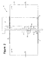
- the base medium takes the form of loose sheets 12, such as paper sheets, to which memory tags 5 have been applied or within which memory tags 5 have been embedded (in Figure 2, the sheet 12 is shown as provided with three memory tags 5A, 5B and 5C).
- the memory tags 5 are RFID memory tags for which the manner of writing data to the tags and reading data from the tags is well known (see for example the RFID Handbook, Klaus Finkenzeller, 1999, John Wiley & Sons). For simplicity only those parts of the apparatus 10 which need to be shown to describe the invention are illustrated and described. It will be understood that the apparatus 10 includes much known technology from the prior art of printers, and from the prior art of RFID memory tags, which is not described here.
- the apparatus 10 comprises a platen 11 and paper feed rollers 14 which are driven, by drive mechanism 18, to rotate as indicated by arrows R1 to feed the sheets 12 across the platen 11 along a first axis in the direction indicated by arrows A1.
- the platen has an upstanding reference edge 13 for locating one edge of the sheet 12 as it is moved across the platen by the rollers 14.
- a leading edge sensor 15 embedded in the platen is arranged to sense the passing of the leading (and trailing) edges of the sheet 12.
- the apparatus 10 further includes a print-head carriage 16 which carries a print head (not separately referenced) which in this example is of ink jet form.
- the print-head carriage 16 is mounted on a guide rail 17 which extends across the apparatus 10 substantially perpendicular to the axis A1.
- the print-head carriage 16 is moveable back and forth along the guide 17 in known manner by drive mechanism 18.
- the print head is moveable back and forth along a second axis indicated by arrows A2, substantially perpendicular to the axis A1, to enable the print head to access most of the upper surface 12A of the paper sheet 12 as it moves through the apparatus 10, and thus to print anywhere on that accessible area of surface 12A as required.
- the print-head carriage 16 also mounts a memory tag read/write device 20, and a marking sensor 28.
- the marking sensor 28 is operative to sense special markings applied to a sheet 12, such as markings made using an infrared-visible ink not visible to the normal human eye and not normally used by the print head; as will be more fully explained hereinafter, such markings are used to provide a way of inputting user selection data to the apparatus 10.
- the memory tag read/write device 20 operates to write data to and/or read data from memory tags 5 as required using an inductive coil L2. Due to its mounting on the carriage 16, the inductive coil L2 of the memory tag read/write device 20 is moveable back and forth along a third axis indicated by arrows A3, substantially perpendicular to the axis A1, and parallel to the axis A2, to enable the memory tag read/write device 20 to read data from and/or write data to memory tags 5 located anywhere on or in the accessible area of the sheet 12.
- a memory tag 5 includes an antenna coil L1 and a capacitor C1 connected in parallel therewith to form a resonant circuit.
- the tag 5 further includes a memory 7 and processing and power circuitry 6.
- the read/write device 20 includes an antenna coil L2 and a capacitor C2 in parallel therewith to form a resonant circuit, and a processing and signal generating circuitry 21.
- a signal generator within circuitry 21 generates a signal at the chosen frequency, such as 2.45GHz; this signal is applied to the antenna coil L2 and thus generates an electromagnetic field which, provided the memory tag 5 is sufficiently close to the read/write device 20, penetrates the antenna coil L1 of the memory tag 5. By induction a voltage is thus generated in the antenna coil L1. This induced voltage is rectified in circuitry 6 and used to power the memory tag 5.
- the capacitance of the capacitors C1 and C2 is selected such that the resonant circuits are both resonant at the frequency generated by the signal generator, in order to maximise transmitted signal strength and received signal.
- the radio frequency signal generated in circuitry 21 is modulated, e.g. amplitude modulated, with the data before being applied to the antenna coil L2 and transmitted.
- the signal received by the memory tag 5 by inductive coupling thus both powers the memory tag 5 and communicates with it, the circuitry 6 separating the data signal from the carrier and passing data for storage to the memory 7.
- the circuitry 6 applies a signal indicative of the data to the antenna coil L1 which is detected, as a result of the inductive coupling, by antenna coil L2 and deciphered in circuitry 21 before being output from the read/write device 20.
- This signal may for example be transmitted using load modulation.
- the power consumed by the memory tag 5 can be measured as a drop in voltage across the internal resistance of the antenna coil L2 of the read/write device 20.
- a load resistance within the circuitry 6 may be switched on and off, thus altering the power consumed by the memory tag 5 which is then detected as an amplitude modulation of the voltage across the antenna coil L2 of the read/write device 20.
- FIG. 4 shows the main functional components in block diagram form.
- the apparatus includes a main processor 22, typically a program-controlled processor, arranged to receive input from an external device (such as a host computer 24), and a mechanism controller 26 for controlling the drive mechanism 18 to move the paper sheet 12 and the print-head carriage 16 as commanded by the main processor 22.
- a main processor 22 typically a program-controlled processor, arranged to receive input from an external device (such as a host computer 24), and a mechanism controller 26 for controlling the drive mechanism 18 to move the paper sheet 12 and the print-head carriage 16 as commanded by the main processor 22.
- the mechanism controller 26 is arranged to position the print head over the sheet 12 at a position specified by the main processor 22 in standard units (such as millimetres) relative to a frame of reference established by the edges of the sheet (in particular, the sheet edge up against the reference edge 13 and the sheet leading edge as detected by sensor 15).
- standard units such as millimetres
- this is achieved by providing for the conversion of the units of measure provided by the processor 22 into the basic positioning units, such as stepping motor increments, used by the drive mechanism 18. This conversion utilises both scaling factors between standard measurement units and drive-mechanism units, and offset values.
- offset values comprise a fixed offset value between the reference edge 13 and the drive mechanism position measure in the direction of axis A2 when the print head is aligned with the edge 13, and the value of the drive mechanism position measure in the direction of axis A1 when the sensor 15 detects the leading edge of the sheet 12.
- the mechanism controller 26 is also arranged to respond to commands from the processor 22 to position either one of the memory tag read/write device 20 and the marking sensor 28 at a specified position above the sheet 12 relative to the sheet-edge frame of reference (it being appreciated that this simply involves the controller 26 positioning the print head at a position offset relative to the specified position by an amount corresponding to the actual offset, relative to the print head, of the element 20 or 28 being positioned).
- the main processor 22 receives data and instruction signals from the host computer 24, including:
- the main processor 22 sends command signals as required to:
- the sheet 12 is fed through the apparatus 10 and has the required information printed on its upper surface 12A.
- the memory tags 5 on or within the paper sheet 12 have the necessary data written to them by the memory tag read/write device 20, with the movement of the memory tag read/write device 20 (and print head 16) being paused with the memory tag read/write device 20 over each memory tag 5 as necessary for the data writing to take place.
- the manner of co-ordination of the printing and data writing processes will depend on a number of factors. If, for example, the memory tags 5 are only present adjacent the top and/or bottom of the paper sheet 12 then the data writing process can take place before and/or after the printing. This would avoid the necessity for the printing process to be interrupted, and would make the co-ordination simpler. Further, when implemented with an inkjet printer, which in general requires a pause, after printing has been completed before the paper sheet is ejected, to allow the ink to dry, the data writing process could conveniently take place during this pause for memory tags present adjacent the bottom of the paper sheet 12.
- the memory tags 5 can have icons printed over their locations which can be readily identified by users.
- the memory tag read/write device 20 may, in addition to writing the data to the memory tags 5, also conduct a read operation to check that the data has written successfully before the paper sheet 12 is moved on following the data write operation.
- a separate data check device (not shown) may be included in the apparatus such that this operation takes place downstream of a memory tag write device which in this case need not also be capable of data reading.
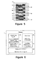
- Figure 5 depicts an example sheet 12 printed and written to by the apparatus.
- the Figure 5 sheet 12 has nine items 50 to 58 printed on it and three memory tags 5A, 5B, 5C that store the print data items corresponding to printed the items 50 to 58.
- Each memory tag has a respective associated "area of responsibility " on the sheet 12, these areas being indicated by dashed boxes 64, 65, and 66 for the tags 5A, 5B and 5C respectively.
- Each tag 5A, 5B, 5C stores the print data items corresponding to the printed items lying within in its respective area of responsibility.
- memory tag 5A stores the print data items 50 and 51 as the corresponding printed items lie within the area of responsibility 64 associated with tag 5A; similarly, tag 5B stores the print data items corresponding to printed items 52 and 53, and tag 5C stores the print data items corresponding to printed items 55-58.
- Figure 5 also indicates, by dotted ovals 60, 61 and 62, three "hot spot" locations on the sheet 12 each of which is associated with a respective meta data item.
- the hot spot locations are locations that if user-selected in an appropriate manner, result in some action being carried out in respect of the corresponding meta data item. The action carried out may be specified by the meta data item itself, by external input, or by the selection context.
- Each meta data item like each print data item, is stored in the tag whose area of responsibility covers the position on the sheet associated with the data item.
- the memory tag 5A stores the meta data item corresponding to dotted oval 60
- the memory 5B stores the meta data items corresponding to the dotted ovals 61 and 62.
- each memory tag 5A, 5B, 5C can be defined either independently of the data items to be written to the memory tags of a sheet, or in dependence on these items.
- the area of responsibility of each memory tag can be pre-defined and stored in the tag (for example, at the time of manufacture of the sheet 12 with the tags attached to / embedded in it); in the latter case, the host computer 24 or apparatus 10 can retrospectively define the area of responsibility of each memory tag 5A, 5B, 5C after have written all the data items associated with the sheet into the memory tags of the sheet.
- the area of responsibility of a tag is pre-defined, it is up to the apparatus to ensure that the data items falling within that area of responsibility are indeed stored to the tag concerned.
- Figure 6 depicts the contents of the memory 7 of one of the memory tags 5A, 5B, 5C after it has been written to by the memory tag read/write device 20.
- the contents of the memory 7 is divided into six data blocks 40 to 45.
- the data block 40 comprises the generic data provided by the host computer 24 and may additionally include data such as a read-only unique reference number for the tag itself, tag compatibility information, and manufacturing details.
- the data block 41 comprises location data in respect of the memory tags 5A, 5B, 5C provided in or on sheet 12; in particular, this data comprises the location of the or each tag relative to the sheet-edge frame of reference. This location need not necessarily be precisely identified but could simply indicate the general location of the tag concerned (where the tags are subsequently to be read by a hand-held reader, the precise location of a tag is unlikely to be of greater utility than its general location).
- the location data comprising block 41 thus enables a reading device to quickly determine where all other memory tags (if any) are located on the sheet.
- the tag location data can be written into the memory tags prior to the sheet being presented to the apparatus 10 (for example, as part of the process for manufacturing the sheets 12).
- the data block 42 comprises location data in respect of the area of responsibility 64, 65, 66 of each of the memory tags 5A, 5B, 5C provided in or on sheet 12. This data facilitates access to data items stored in the memory tags by indicating which tag 5 is the appropriate one to access for data concerning a particular area of the sheet. As already explained, where the area of responsibility of a tag is pre-defined, the area-of-responsibility location data stored in the tag is used to determine which data items are stored to the tag.
- the data block 43 comprises the print data items and the meta data items provided by the host computer 24.
- the data block 44 comprises a map that relates areas of the sheet 12 (more particularly, the printed areas and the meta-data hotspots) to specific print or meta data items held in data block 43.
- the data block 45 comprises a global index for the sheet, this index relating each data item by title and type (print or meta) to the tag 5A, 5B, or 5C in which it is stored.
- the data block 41 comprising the tag locations will generally always be present, one or more of the data blocks 42, 44 and 45 may be omitted according to circumstances. In fact, the data block 41 can be omitted in certain cases though then either the data block 42 will be present or data equivalent to that of data block 41 will be held in the memory 7.
- the sheet 12 can be used in a variety of ways.
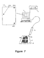
- the sheet 12 is provided to a person with access to a hand-held memory-tag reader 70 connected to a general purpose computer 71 (see Figure 7).
- the data blocks 40 and 41 are read into the computer 71 and used to display a graphical representation 112 of the sheet 12 with indications 105A, 105B, and 105C showing the locations of all the memory tags on the sheet 12.
- all references above 100 refer to displayed features; where a displayed feature corresponds to a referenced physical feature, such as the sheet 12 or one of the tags 5A, 5B, 5C, then the reference used for the displayed feature is 100 more than the reference used for the corresponding physical feature).
- the user Since the user has the printed sheet 12, it is a simple matter to determine from the location of an item of interest on the sheet 12 and the Figure 8 displayed graphical representation 112 of the sheet, which tag should be accessed to read the data item corresponding to the item of interest.
- the data item Once the data item has been accessed, it can be utilised as required; for example it can be individually printed (possibly after editing) on a standard printer 72, stored in the computer, or forwarded electronically.
- the reader 70 when reading a memory tag the reader 70 will typically read all the data blocks.
- the contents of the data-item data block 43 will normally be read into the computer 71 whereby the graphical representation 112 of the sheet can be supplemented by a display of the print data items in their corresponding locations on the sheet (see Figure 9 which shows displayed print data items 150, 151 corresponding to the print data items read from tag 5A and therefore located within the displayed area-of-responsibility box164 of that tag).
- the presence of meta data items can also be indicated (see dashed oval 160 indicative of hotspot 60) and, indeed, the meta data items can be set out in full on the screen of the computer 71.
- this index can conveniently be displayed in the form of a respective sub-index 180, 181, 182 for each tag, each sub-index being displayed within the area-of-responsibility box of the corresponding tag (see Figure 10). Again, this sub-index display facilitates access to a data item of interest.
- the sub-indexes 180, 181 and 182 can be displayed against the corresponding tag location indications 105A, 105B, 105C as is indicated in Figure 11.
- Figure 12 shows a sub-index display similar to that of Figure 11 but for the case where the data items associated with the sheet have been differently organised when written to the tags 5A, 5B, 5C.
- tag 5C now holds all the meta data items whilst the print data items are split between the tags 5A and 5B - in particular, tag 5A holds the print data items corresponding to printed items 50, 52, 53, 55 and 56, and the tag 5B holds the print data items corresponding to printed items 51, 54, 57 and 58. Because of this split of data items between tags, it is no longer possible to define a simple division of the sheet 12 into areas of responsibility for each tag. Whilst it would be possible to provide the data block 42 as the areas of each data item stored for each tag (thereby producing a composite "area of responsibility" for each tag), it is preferable to rely on the map data of data block 44, where written.
- the item map comprising data block 44 enables the display of the areas of the sheet associated with data items held by each of the tags.
- lines are used to indicate in which tag the data item corresponding to each item area is stored (the relation between data item and tag being derived from the global index that comprises the data block 44).
- Other ways of indicating the association data item location and tag are, of course, possible such as by colour coding.
- Figure 13 display will only be possible if the data block 44 of the tag being read comprises a data item map for all data items associated with a sheet; if each tag only holds a data item map for the items it stores, then the association of data-item-area to tag can only be displayed for the or each tag that has been read (thus, where all tags have been read, Figure 13 can be fully displayed).
- FIG. 14 is a diagram showing, in a more systematic manner, how the various mappings held by a tag can be used to inter-relate data elements and help a user access a desired data item.
- four data elements are shown, namely, tag ID, tag location, item ID and sheet location. These elements are related as follows:
- mappings are, of course, two way.
- a user will select a data item of interest either by an associated data-item ID (including an associated descriptive element such as a title), or by its location on the sheet; these two selection routes are indicated by the dotted arrows 90, 91 in Figure 14.
- the mappings serve to provide a connection between an item-ID/sheet-location that identifies a data item of interest, and the location of the tag holding that item.
- mappings 93 and 94 represent mapping directly linking item ID to the sheet location of the corresponding tag
- arrow 94 represents a mapping directly linking a sheet location with the sheet location of the corresponding tag.
- mappings 41, 42, 44, and 45 can be stored in a memory tag in addition to, or as an alternative to one or more of the mappings 41, 42, 44, and 45 and used to produce displays similar to those already described above for helping a user access the tag holding an item of interest.
- mapping 44 (assuming it is present) can be used to convert an item selection input in the form of a sheet location/item-ID into an item-ID/sheet location whereby either form of selection input can be used with the available mapping represented by arrow 93/94 to identify the location of the tag holding the selected data item.
- mappings held in the memory tags have simply been used to provide visual indications to a user to guide the user where to look for the desired data item, this being because the user is in charge of positioning the memory tag reader 70.
- the memory tags being read using a hand-held reader, it is possible to read the tags using a machine-positioned memory-tag reader such as is provided by the apparatus 10 of Figures 1 and 2.
- the printed and written-to sheet 12 could be fed into apparatus of the form shown in Figures 1 and 2 with this apparatus being set in "read" mode, and the contents of the memory tags 5 read into a memory portion of the main processor 22 of the apparatus 10.
- the locations of the remaining tags will be known to the processor 22 which can then command the controller to move the read/write device 20 over each such remaining memory tag in turn without the need to scan the sheet 12 to locate them.
- Another way of enabling a first tag to be found is always to provide a tag at a standard, known, location on the sheet 12.
- the user's selection can be input in a number of different ways.
- the apparatus can be connected to a host computer 24 and the mappings 41, 42, 44, 45 used to produce the same sort of displays as described above with reference to Figures 7 to 13.
- the user can make a selection using a pointing device (such as a mouse or a touch-screen display) with the host computer 24 being arranged to recognise the location of the display pointed at, and convert this location either directly into a data item ID or first into a location on the sheet 12 and then via the mapping 43 into an item ID. Any appropriate action can then be effected in relation to that data item.
- a pointing device such as a mouse or a touch-screen display
- the apparatus will typically automatically read all the memory tags as soon as the sheet 12 is provided to it; as a result, the data items will normally already have been read into the host computer 24 at the time the user selects a data item via the display so that it will not be necessary to subsequently use the mappings to determine the location of the tag holding a data item (unless that data item is to be deleted or modified).
- FIG 15 Another way of making a user selection of a data item is illustrated in Figure 15 where the sheet 12 is shown as marked with two crosses 98 and 99 to indicate that the user is interested both in the print data item corresponding to printed item 50 and in the meta data item corresponding to hotspot 61.
- These markings 98, 99 are made using a marking ink to which the marking sensor 28 of apparatus 10 is sensitive.
- the sheet 12 is then fed into the apparatus 10 where it is scanned and the memory tags read; in addition, the sensor 28 detects the markings 98 and 99 and the locations of these markings are passed to the processor 22.
- the processor 22 (or a related host computer) converts these locations to the corresponding data items using the mapping 44 and takes appropriate action (for example, prints individual copies of each item or displays these items, depending on the instructions provided by the user).
- Figure 16 depicts a further way of inputting user selection, this time by the use of a graphics tablet 74.
- the graphics tablet is of standard form with a pressure sensitive surface 75 on which the sheet 12 is placed up against positioning reference edges 76, 77.
- the sheet has previously been fed through the apparatus 10 and the data stored in its memory tags read off and passed to host computer 24.
- a stylus 78 is used to select particular points on the sheet 12 by pressing down on the sheet at the appropriate locations.
- the position coordinates of each selected point are passed by the graphics tablet to the host computer 24 which uses these coordinates and the mapping 44 to determine what data item has been selected.
- each tag can simply contain the location of a subset (such as one) of the other tags whereby to link the tags into a chain , tree or other single tag-organisation structure; of course, the tag or tags at the end or ends of such a structure (for example, the leaf tags of a tree structure) would not need to hold the location of another tag.
- a tag need not contain its own location on the basis that the reader will in any case know this location (though the stored location of a tag being read can provide useful feedback to the apparatus regarding the accuracy of its positioning system).
- mappings held by a memory tag that where a mapping is ostensibly global (that is, it relates to all tags / data items of the sheet 12), it may in fact be possible to omit the mapping data relating to the tag holding the mapping as the mapping data for that tag is either not needed or is otherwise derivable.
- the location of the tag will be known at the time it is read so need not be included in the data block 41, and the data items held in the tag will similarly be known when the tag is read and so need not be listed in the global index 45.
- the memory tag read/write device 20 can be mounted on a read/write device carriage for movement independent of movement of the print head carriage movement.
- the read/write device carriage can be located either upstream or downstream of the print head carriage 18 and the mechanism controller 26 is arranged to position the read/write device carriage relative to the frame of reference established by the edges of the sheet 12 in the same manner as described above for the print-head carriage.
- the edges of the sheet for establishing a frame of reference for positioning elements of the apparatus 10 (in particular, the print head 16 and/or the read/write device 20, and/or the sensor 28) over the sheet 12
- other frames of reference can be used.
- the positioning pattern could be provided pre-printed on the sheet 12 or could be printed by the print head 16 (though in this case it will typically still be necessary to use the sheet edges and the drive mechanism scaling factors to determine where to print the pattern).
- a further possibility for establishing a frame of reference for positioning is to use the location of a memory tag 5 embedded in, or attached to, the sheet 12 as the origin point of the frame of reference, the drive mechanism being calibrated to provide measures of displacement from this origin along axes defined by the mechanics of the apparatus and the orientation of the sheet.
- the sheet orientation will often be determined by the sheet edges abutting reference guides. However, since these edges could be damaged over time, it is preferable to provide some way of defining sheet orientation independently of the sheet edges.
- the sheet could initially be printed with markings defining axes (typically orthogonal axes) or the memory tag could be printed or physically formed with orientation markings that the apparatus could detect and use to orient the sheet 12 correspondingly.
- the memory tag could be printed or physically formed with orientation markings that the apparatus could detect and use to orient the sheet 12 correspondingly.
- two or more memory tags could be positioned in or on the sheet such as to define sheet orientation, the apparatus again being arranged to orient the sheet 12 correspondingly or to computationally adjust for the orientation of the sheet.
- the frame of reference used for sheet locations will not have its origin point coincident with the location of a memory tag, it is still possible for the location data stored by a memory tag to specify locations on the sheet relative to its own location.
- the location data comprising the data block 41 of a memory tag can specify the locations of the other memory tags relative to the location of the tag storing the data.
- the apparatus Rather than the memory tag(s) being embedded in, or attached to, the sheet 12 prior to the sheet being introduced into the apparatus, it is possible to arrange for the apparatus to have a supply of memory tags with the apparatus first writing data to a tag before adhering it to the corresponding sheet, typically after it has printed the latter.
- both the writing and reading of the memory tags can be effected independently of any print operations and can be effected by apparatus without any printing capabilities. Indeed, in certain cases, the sheet 12 can be devoid of any printing (as would be the case if the only data items held by the memory tags were meta data items).
- embodiments have been described as appropriate for use with base media in the form of loose sheets 12.
- embodiments can also be constructed for use with other base media, for example paper in fan fold or roll form, or indeed boxes or other objects (the term "base medium” in this context simply referring to the portion of the object not constituted by the memory tags).
- the memory tags 5 have all used RFID technology. However, it is also possible to use memory tags which operate at other frequencies, outside the radio frequency range.
Landscapes
- Engineering & Computer Science (AREA)
- Physics & Mathematics (AREA)
- General Physics & Mathematics (AREA)
- Theoretical Computer Science (AREA)
- Toxicology (AREA)
- Computer Vision & Pattern Recognition (AREA)
- Health & Medical Sciences (AREA)
- Artificial Intelligence (AREA)
- Computer Hardware Design (AREA)
- Microelectronics & Electronic Packaging (AREA)
- Computer Networks & Wireless Communication (AREA)
- Electromagnetism (AREA)
- General Health & Medical Sciences (AREA)
- Record Information Processing For Printing (AREA)
- Accessory Devices And Overall Control Thereof (AREA)
- Recording Measured Values (AREA)
Applications Claiming Priority (2)
| Application Number | Priority Date | Filing Date | Title |
|---|---|---|---|
| GBGB0402035.0A GB0402035D0 (en) | 2004-01-30 | 2004-01-30 | Physical object with memory tags and apparatus for writing and using such objects |
| GB0402035 | 2004-01-30 |
Publications (3)
| Publication Number | Publication Date |
|---|---|
| EP1560148A2 true EP1560148A2 (de) | 2005-08-03 |
| EP1560148A3 EP1560148A3 (de) | 2006-12-27 |
| EP1560148B1 EP1560148B1 (de) | 2010-04-07 |
Family
ID=31971730
Family Applications (1)
| Application Number | Title | Priority Date | Filing Date |
|---|---|---|---|
| EP05100160A Ceased EP1560148B1 (de) | 2004-01-30 | 2005-01-12 | Physisches Objekt mit Speicheretiketten und Gerät zum Beschreiben und Benützen eines solchen Objekts |
Country Status (5)
| Country | Link |
|---|---|
| US (1) | US8183979B2 (de) |
| EP (1) | EP1560148B1 (de) |
| JP (1) | JP4141446B2 (de) |
| DE (1) | DE602005020378D1 (de) |
| GB (1) | GB0402035D0 (de) |
Cited By (3)
| Publication number | Priority date | Publication date | Assignee | Title |
|---|---|---|---|---|
| EP2085913A1 (de) * | 2008-02-01 | 2009-08-05 | Brother Kogyo Kabushiki Kaisha | Vorrichtung zur Kommunikation mit RFID-Etikett, Vorrichtung zur Herstellung von RFID-Etiketten und Etikettenbildverwaltungssystem |
| EP2088541A1 (de) * | 2008-01-31 | 2009-08-12 | Semiconductor Energy Laboratory Co., Ltd. | Halbleitervorrichtung |
| WO2015039991A1 (en) * | 2013-09-17 | 2015-03-26 | Oce-Technologies B.V. | Method for tracking image data printed on a piece of media |
Families Citing this family (29)
| Publication number | Priority date | Publication date | Assignee | Title |
|---|---|---|---|---|
| US20060278716A1 (en) * | 2005-05-31 | 2006-12-14 | Semiconductor Energy Laboratory Co., Ltd. | Input device and input system |
| JP2007018198A (ja) * | 2005-07-06 | 2007-01-25 | Sony Corp | リンク情報付きインデックス情報生成装置、タグ情報付き画像データ生成装置、リンク情報付きインデックス情報生成方法、タグ情報付き画像データ生成方法及びプログラム |
| CN1326072C (zh) * | 2005-09-28 | 2007-07-11 | 广东溢达纺织有限公司 | 应用射频识别技术的成衣生产跟踪系统 |
| US7978936B1 (en) | 2006-01-26 | 2011-07-12 | Adobe Systems Incorporated | Indicating a correspondence between an image and an object |
| US7706577B1 (en) | 2006-01-26 | 2010-04-27 | Adobe Systems Incorporated | Exporting extracted faces |
| US8259995B1 (en) | 2006-01-26 | 2012-09-04 | Adobe Systems Incorporated | Designating a tag icon |
| US7319421B2 (en) * | 2006-01-26 | 2008-01-15 | Emerson Process Management | Foldback free capacitance-to-digital modulator |
| US7716157B1 (en) | 2006-01-26 | 2010-05-11 | Adobe Systems Incorporated | Searching images with extracted objects |
| US7694885B1 (en) * | 2006-01-26 | 2010-04-13 | Adobe Systems Incorporated | Indicating a tag with visual data |
| US7813526B1 (en) | 2006-01-26 | 2010-10-12 | Adobe Systems Incorporated | Normalizing detected objects |
| US7813557B1 (en) | 2006-01-26 | 2010-10-12 | Adobe Systems Incorporated | Tagging detected objects |
| US7720258B1 (en) | 2006-01-26 | 2010-05-18 | Adobe Systems Incorporated | Structured comparison of objects from similar images |
| US7636450B1 (en) | 2006-01-26 | 2009-12-22 | Adobe Systems Incorporated | Displaying detected objects to indicate grouping |
| JP2008078777A (ja) * | 2006-09-19 | 2008-04-03 | Brother Ind Ltd | 印刷物管理装置 |
| JP4379453B2 (ja) * | 2006-09-19 | 2009-12-09 | ブラザー工業株式会社 | 画像形成装置 |
| JP2008076851A (ja) * | 2006-09-22 | 2008-04-03 | Brother Ind Ltd | 画像記録装置 |
| JP2008074068A (ja) * | 2006-09-25 | 2008-04-03 | Brother Ind Ltd | 画像形成装置 |
| JP2008074067A (ja) * | 2006-09-25 | 2008-04-03 | Brother Ind Ltd | 画像形成装置 |
| JP4265641B2 (ja) * | 2006-09-27 | 2009-05-20 | ブラザー工業株式会社 | 画像形成装置及びプログラム |
| JP4197027B2 (ja) | 2006-09-28 | 2008-12-17 | ブラザー工業株式会社 | 画像形成装置及びプログラム |
| JP2008085844A (ja) * | 2006-09-28 | 2008-04-10 | Brother Ind Ltd | データ処理装置及び被記録媒体 |
| JP2008084152A (ja) * | 2006-09-28 | 2008-04-10 | Brother Ind Ltd | 画像形成装置及びプログラム |
| JP2008090340A (ja) * | 2006-09-29 | 2008-04-17 | Brother Ind Ltd | 文書データ編集装置、文書作成システム、及びプログラム |
| US9507375B2 (en) * | 2007-06-05 | 2016-11-29 | Samsung Electronics Co., Ltd. | Display apparatus and method for recognizing location |
| US8446253B2 (en) * | 2009-03-11 | 2013-05-21 | Checkpoint Systems, Inc. | Localization using virtual antenna arrays in modulated backscatter RFID systems |
| CA2762492C (en) * | 2009-05-22 | 2016-06-14 | Berntsen International, Inc. | System, method and monument for land surveying |
| AU2013208256C1 (en) * | 2012-01-10 | 2015-03-05 | Neonode Inc. | Combined radio-frequency identification and touch input for a touch screen |
| WO2017205619A1 (en) | 2016-05-27 | 2017-11-30 | Berntsen International, Inc. | Uhf rfid tag for marking underground assets and locations and methods of using same |
| US11886949B2 (en) * | 2019-06-14 | 2024-01-30 | Rfid Paper Sdn Bhd | Radio frequency identification flat sheet |
Family Cites Families (20)
| Publication number | Priority date | Publication date | Assignee | Title |
|---|---|---|---|---|
| JPH0616312B2 (ja) | 1980-06-23 | 1994-03-02 | ライト・シグネイチヤ−ズ、インコ−ポレテツド | 偽造防止ドキュメントシステム |
| US5418865A (en) * | 1992-03-20 | 1995-05-23 | Xerox Corporation | Mark sensing on a form |
| US5689238A (en) * | 1996-03-08 | 1997-11-18 | Lucent Technologies, Inc. | Object locator system and methods therefor |
| US6297727B1 (en) * | 1997-05-05 | 2001-10-02 | George N. Nelson, Jr. | Transponder identification and record assembly |
| US6847334B2 (en) * | 1998-06-29 | 2005-01-25 | William Hayhurst | Mobile telecommunication device for simultaneously transmitting and receiving sound and image data |
| US6176425B1 (en) * | 1998-09-10 | 2001-01-23 | Xerox Corporation | Information management system supporting multiple electronic tags |
| US6008727A (en) * | 1998-09-10 | 1999-12-28 | Xerox Corporation | Selectively enabled electronic tags |
| US6446208B1 (en) * | 1998-09-10 | 2002-09-03 | Xerox Corporation | User interface system based on sequentially read electronic tags |
| US6964374B1 (en) * | 1998-10-02 | 2005-11-15 | Lucent Technologies Inc. | Retrieval and manipulation of electronically stored information via pointers embedded in the associated printed material |
| EP0992953A3 (de) * | 1998-10-08 | 2004-06-02 | Canon Kabushiki Kaisha | Schnittstellensystem für benutzerprogammierbare Chipkarten |
| US6262662B1 (en) * | 2000-02-25 | 2001-07-17 | Xerox Corporation | Systems and methods that detect proximity information using electric field sensing devices and a page identification using embedded identification tags |
| US6668156B2 (en) * | 2000-04-27 | 2003-12-23 | Leapfrog Enterprises, Inc. | Print media receiving unit including platform and print media |
| US6879332B2 (en) * | 2000-05-16 | 2005-04-12 | Groxis, Inc. | User interface for displaying and exploring hierarchical information |
| JP3912031B2 (ja) * | 2001-05-15 | 2007-05-09 | 株式会社デンソーウェーブ | 複写機およびファクシミリ装置 |
| US6967566B2 (en) * | 2002-04-05 | 2005-11-22 | Creative Kingdoms, Llc | Live-action interactive adventure game |
| US7506250B2 (en) * | 2002-09-03 | 2009-03-17 | Ricoh Company, Ltd. | Techniques for determining electronic document information for paper documents |
| US7170391B2 (en) * | 2002-11-23 | 2007-01-30 | Kathleen Lane | Birth and other legal documents having an RFID device and method of use for certification and authentication |
| US7010647B1 (en) * | 2002-12-13 | 2006-03-07 | The United States Of America As Represented By The Secretary Of The Army | Computer system with removable data storage device and method |
| US7023344B2 (en) * | 2002-12-20 | 2006-04-04 | Sap Ag | Smart documents and process for tracking same |
| GB2404271B (en) * | 2003-07-24 | 2006-06-21 | Hewlett Packard Development Co | Print having attached data storage, storage medium therefore and method of providing same |
-
2004
- 2004-01-30 GB GBGB0402035.0A patent/GB0402035D0/en not_active Ceased
-
2005
- 2005-01-12 DE DE602005020378T patent/DE602005020378D1/de not_active Expired - Lifetime
- 2005-01-12 EP EP05100160A patent/EP1560148B1/de not_active Ceased
- 2005-01-14 US US11/035,801 patent/US8183979B2/en not_active Expired - Fee Related
- 2005-01-31 JP JP2005023766A patent/JP4141446B2/ja not_active Expired - Fee Related
Cited By (4)
| Publication number | Priority date | Publication date | Assignee | Title |
|---|---|---|---|---|
| EP2088541A1 (de) * | 2008-01-31 | 2009-08-12 | Semiconductor Energy Laboratory Co., Ltd. | Halbleitervorrichtung |
| US8432254B2 (en) | 2008-01-31 | 2013-04-30 | Semiconductor Energy Laboratory Co., Ltd. | Semiconductor device |
| EP2085913A1 (de) * | 2008-02-01 | 2009-08-05 | Brother Kogyo Kabushiki Kaisha | Vorrichtung zur Kommunikation mit RFID-Etikett, Vorrichtung zur Herstellung von RFID-Etiketten und Etikettenbildverwaltungssystem |
| WO2015039991A1 (en) * | 2013-09-17 | 2015-03-26 | Oce-Technologies B.V. | Method for tracking image data printed on a piece of media |
Also Published As
| Publication number | Publication date |
|---|---|
| JP4141446B2 (ja) | 2008-08-27 |
| US20050172215A1 (en) | 2005-08-04 |
| US8183979B2 (en) | 2012-05-22 |
| DE602005020378D1 (de) | 2010-05-20 |
| EP1560148A3 (de) | 2006-12-27 |
| JP2005285094A (ja) | 2005-10-13 |
| GB0402035D0 (en) | 2004-03-03 |
| EP1560148B1 (de) | 2010-04-07 |
Similar Documents
| Publication | Publication Date | Title |
|---|---|---|
| US8183979B2 (en) | Physical object with memory tags and apparatus for writing and using such objects | |
| US7475956B2 (en) | Apparatus for printing, data writing to memory tags and data reading from memory tags, and methods therefor | |
| EP1431903B1 (de) | Detektor | |
| US7164353B2 (en) | Method and system for testing RFID devices | |
| EP1422068A1 (de) | Gerät zum Drucken und Auftragen eines Speicheridentifizierungskennzeichens und Verfahren dafür | |
| JP2002120475A (ja) | 紙製品、書類管理方法、書類管理システム、事務用品および事務機器 | |
| US7552875B2 (en) | Print media with attached data storage and method of storing data thereon | |
| US20090108994A1 (en) | Two sided thermal rfid | |
| US7948647B2 (en) | Production workflow integration system | |
| EP1560156B1 (de) | Verfahren und Vorrichtung zum Schreiben in ein Speicheretikett | |
| US7900844B2 (en) | Configurable RFID apparatus and process | |
| US7746217B2 (en) | Reading from and writing to memory tags | |
| JP2002230491A (ja) | 非接触icタグを用いた書類または物品の検索方法と当該方法に使用する非接触icタグリーダ | |
| US8205799B2 (en) | Physical object with memory tag and apparatus for use with such objects | |
| EP2725461B1 (de) | Informationsverwaltungsvorrichtung und Speichermedium mit darauf gespeichertem Informationsverwaltungsprogramm | |
| EP2977885A1 (de) | Informationseingabevorrichtung, steuerungsverfahren und steuerungsprogramm | |
| US8089650B2 (en) | Connected offline finishing devices | |
| JP6123597B2 (ja) | 筆記データ処理装置 | |
| JPH0962817A (ja) | データキャリア付衣服、リネンサプライシステム及びリネン用データキャリア | |
| JP2004046689A (ja) | Rf−idシート及びこれを発行するシート発行装置 | |
| US20070034678A1 (en) | Configurable RFID apparatus and process | |
| JP4184744B2 (ja) | 電子ペン用書籍管理票 | |
| GB2413423A (en) | Document processing device | |
| JP4328142B2 (ja) | 情報入力装置 | |
| KR20170077493A (ko) | 휴대용 rfid 라벨 프린터 및 rfid 라벨 출력방법 |
Legal Events
| Date | Code | Title | Description |
|---|---|---|---|
| PUAI | Public reference made under article 153(3) epc to a published international application that has entered the european phase |
Free format text: ORIGINAL CODE: 0009012 |
|
| AK | Designated contracting states |
Kind code of ref document: A2 Designated state(s): AT BE BG CH CY CZ DE DK EE ES FI FR GB GR HU IE IS IT LI LT LU MC NL PL PT RO SE SI SK TR |
|
| AX | Request for extension of the european patent |
Extension state: AL BA HR LV MK YU |
|
| PUAL | Search report despatched |
Free format text: ORIGINAL CODE: 0009013 |
|
| AK | Designated contracting states |
Kind code of ref document: A3 Designated state(s): AT BE BG CH CY CZ DE DK EE ES FI FR GB GR HU IE IS IT LI LT LU MC NL PL PT RO SE SI SK TR |
|
| AX | Request for extension of the european patent |
Extension state: AL BA HR LV MK YU |
|
| 17P | Request for examination filed |
Effective date: 20070424 |
|
| AKX | Designation fees paid |
Designated state(s): DE FR GB |
|
| 17Q | First examination report despatched |
Effective date: 20070823 |
|
| GRAP | Despatch of communication of intention to grant a patent |
Free format text: ORIGINAL CODE: EPIDOSNIGR1 |
|
| GRAS | Grant fee paid |
Free format text: ORIGINAL CODE: EPIDOSNIGR3 |
|
| GRAA | (expected) grant |
Free format text: ORIGINAL CODE: 0009210 |
|
| AK | Designated contracting states |
Kind code of ref document: B1 Designated state(s): DE FR GB |
|
| REG | Reference to a national code |
Ref country code: GB Ref legal event code: FG4D |
|
| REF | Corresponds to: |
Ref document number: 602005020378 Country of ref document: DE Date of ref document: 20100520 Kind code of ref document: P |
|
| PLBE | No opposition filed within time limit |
Free format text: ORIGINAL CODE: 0009261 |
|
| STAA | Information on the status of an ep patent application or granted ep patent |
Free format text: STATUS: NO OPPOSITION FILED WITHIN TIME LIMIT |
|
| 26N | No opposition filed |
Effective date: 20110110 |
|
| REG | Reference to a national code |
Ref country code: DE Ref legal event code: R082 Ref document number: 602005020378 Country of ref document: DE Representative=s name: SCHOPPE, ZIMMERMANN, STOECKELER, ZINKLER & PAR, DE |
|
| REG | Reference to a national code |
Ref country code: DE Ref legal event code: R082 Ref document number: 602005020378 Country of ref document: DE Representative=s name: SCHOPPE, ZIMMERMANN, STOECKELER, ZINKLER, SCHE, DE Effective date: 20140225 Ref country code: DE Ref legal event code: R082 Ref document number: 602005020378 Country of ref document: DE Representative=s name: SCHOPPE, ZIMMERMANN, STOECKELER, ZINKLER & PAR, DE Effective date: 20140225 Ref country code: DE Ref legal event code: R081 Ref document number: 602005020378 Country of ref document: DE Owner name: QUALCOMM INCORPORATED, SAN DIEGO, US Free format text: FORMER OWNER: HEWLETT-PACKARD DEVELOPMENT COMPANY, L.P., HOUSTON, TEX., US Effective date: 20140225 Ref country code: DE Ref legal event code: R081 Ref document number: 602005020378 Country of ref document: DE Owner name: QUALCOMM INCORPORATED, US Free format text: FORMER OWNER: HEWLETT-PACKARD DEVELOPMENT CO., L.P., HOUSTON, US Effective date: 20140225 |
|
| REG | Reference to a national code |
Ref country code: GB Ref legal event code: 732E Free format text: REGISTERED BETWEEN 20150305 AND 20150311 |
|
| REG | Reference to a national code |
Ref country code: FR Ref legal event code: PLFP Year of fee payment: 12 |
|
| REG | Reference to a national code |
Ref country code: FR Ref legal event code: PLFP Year of fee payment: 13 |
|
| REG | Reference to a national code |
Ref country code: FR Ref legal event code: PLFP Year of fee payment: 14 |
|
| PGFP | Annual fee paid to national office [announced via postgrant information from national office to epo] |
Ref country code: FR Payment date: 20191226 Year of fee payment: 16 |
|
| PGFP | Annual fee paid to national office [announced via postgrant information from national office to epo] |
Ref country code: DE Payment date: 20191218 Year of fee payment: 16 Ref country code: GB Payment date: 20191231 Year of fee payment: 16 |
|
| REG | Reference to a national code |
Ref country code: DE Ref legal event code: R119 Ref document number: 602005020378 Country of ref document: DE |
|
| GBPC | Gb: european patent ceased through non-payment of renewal fee |
Effective date: 20210112 |
|
| PG25 | Lapsed in a contracting state [announced via postgrant information from national office to epo] |
Ref country code: FR Free format text: LAPSE BECAUSE OF NON-PAYMENT OF DUE FEES Effective date: 20210131 |
|
| PG25 | Lapsed in a contracting state [announced via postgrant information from national office to epo] |
Ref country code: DE Free format text: LAPSE BECAUSE OF NON-PAYMENT OF DUE FEES Effective date: 20210803 Ref country code: GB Free format text: LAPSE BECAUSE OF NON-PAYMENT OF DUE FEES Effective date: 20210112 |