EP1560185A2 - Dispositif auto-alimenté de sortie de signal pour une bicyclette et appareil d'affichage utilisant ledit dispositif - Google Patents
Dispositif auto-alimenté de sortie de signal pour une bicyclette et appareil d'affichage utilisant ledit dispositif Download PDFInfo
- Publication number
- EP1560185A2 EP1560185A2 EP05001149A EP05001149A EP1560185A2 EP 1560185 A2 EP1560185 A2 EP 1560185A2 EP 05001149 A EP05001149 A EP 05001149A EP 05001149 A EP05001149 A EP 05001149A EP 1560185 A2 EP1560185 A2 EP 1560185A2
- Authority
- EP
- European Patent Office
- Prior art keywords
- bicycle
- coil
- magnet
- moving part
- unit
- Prior art date
- Legal status (The legal status is an assumption and is not a legal conclusion. Google has not performed a legal analysis and makes no representation as to the accuracy of the status listed.)
- Granted
Links
- 230000033001 locomotion Effects 0.000 claims abstract description 9
- 230000005540 biological transmission Effects 0.000 claims description 26
- 230000001105 regulatory effect Effects 0.000 claims description 4
- 239000003990 capacitor Substances 0.000 description 4
- 235000014676 Phragmites communis Nutrition 0.000 description 3
- 238000006243 chemical reaction Methods 0.000 description 3
- 238000010586 diagram Methods 0.000 description 2
- 239000004973 liquid crystal related substance Substances 0.000 description 2
- RYGMFSIKBFXOCR-UHFFFAOYSA-N Copper Chemical compound [Cu] RYGMFSIKBFXOCR-UHFFFAOYSA-N 0.000 description 1
- 229910021417 amorphous silicon Inorganic materials 0.000 description 1
- 230000001143 conditioned effect Effects 0.000 description 1
- 230000001186 cumulative effect Effects 0.000 description 1
- 230000003247 decreasing effect Effects 0.000 description 1
- LTMHDMANZUZIPE-PUGKRICDSA-N digoxin Chemical compound C1[C@H](O)[C@H](O)[C@@H](C)O[C@H]1O[C@@H]1[C@@H](C)O[C@@H](O[C@@H]2[C@H](O[C@@H](O[C@@H]3C[C@@H]4[C@]([C@@H]5[C@H]([C@]6(CC[C@@H]([C@@]6(C)[C@H](O)C5)C=5COC(=O)C=5)O)CC4)(C)CC3)C[C@@H]2O)C)C[C@@H]1O LTMHDMANZUZIPE-PUGKRICDSA-N 0.000 description 1
- 230000005611 electricity Effects 0.000 description 1
- 239000003792 electrolyte Substances 0.000 description 1
- 230000005674 electromagnetic induction Effects 0.000 description 1
- 230000004048 modification Effects 0.000 description 1
- 238000012986 modification Methods 0.000 description 1
- 238000004804 winding Methods 0.000 description 1
- 229910000859 α-Fe Inorganic materials 0.000 description 1
Images




Classifications
-
- G—PHYSICS
- G08—SIGNALLING
- G08C—TRANSMISSION SYSTEMS FOR MEASURED VALUES, CONTROL OR SIMILAR SIGNALS
- G08C17/00—Arrangements for transmitting signals characterised by the use of a wireless electrical link
Definitions
- the present invention is directed to bicycles and, more particularly, to a self-powered bicycle signal output device and equipment that may use such a device.
- cycle computers display riding information such as bicycle speed and riding distance.
- Such cycle computers typically comprise a rotation sensor and a parameter display device, wherein the rotation sensor outputs rotation signals in accordance with the rotation of a wheel, and the riding parameter display device displays bicycle speed and riding distance in response to the output rotation signals. It is also known to transmit the rotation signals wirelessly from the rotation sensor to the display device.
- the device disclosed therein comprises a display unit and a signal generating unit for generating the rotation signals.
- the signal generating unit comprises a reed switch and a transmitting unit, wherein the reed switch detects the passage of a magnet attached to a spoke of the wheel, and the transmitting unit wirelessly transmits the rotation signals generated by the reed switch.
- the signal generating unit operates using a battery as the power source.
- the display unit comprises a case attached to a handlebar of the bicycle. In the case are provided a receiving unit that receives the transmitted rotation signals, a signal conversion unit that converts the received rotation signals to speed indicating information, and a display that displays the speed indicating information.
- the display unit also operates using a battery as the power source.
- a bicycle signal output device comprises a magnet structured to be mounted to one of a stationary part and a moving part of a bicycle, a coil structured to be mounted to the other one of the stationary part and the moving part of the bicycle, and a signal generating unit that operates using electrical power generated by the coil in response to relative motion between the magnet and the coil. Additional inventive features will become apparent from the description below, and such features alone or in combination with the above features may form the basis of further inventions as recited in the claims and their equivalents.
- Fig. 1 is a side view of a particular embodiment of a bicycle 101.
- Bicycle 101 is a sport bicycle of a mountain bicycle type, and it comprises a frame 102, a front fork 103 rotatably mounted to frame 102, a handlebar assembly 104 mounted to the upper part of fork 103, a front wheel 105 rotatably attached to the lower part of fork 103, a rear wheel 106 rotatably attached to the rear of frame 102, a chain 107, a front transmission 108 disposed at the lower middle portion of frame 102, a rear transmission 109 disposed at the rear of frame 102, and a saddle 111 mounted to the upper middle portion of frame 102.
- a front wheel brake 116 is provided for braking front wheel 105, and a rear wheel brake 117 is provided for braking rear wheel 106.
- respective grips 112a, 112b and brake levers 113a, 113b are provided at opposite ends of handlebar assembly 104.
- Brake lever 113b is connected to front wheel brake 116 for braking front wheel 105, and brake lever 113a is connected to rear wheel brake 117 for braking rear wheel 106.
- Front transmission 108 transmits the pedaling force generated by the rider to rear transmission 109 via chain 107.
- Front transmission 108 comprises a plurality of, e.g., three sprockets 137 of various sizes and a front derailleur 133.
- the three sprockets 137 are installed on a gear crank 131 that is rotated when the rider pushes pedals 132a and 132b.
- Gear crank 131 comprises a crankshaft 134 that passes horizontally and rotatably through the central lower part of frame 102, a right crank 135, and a left crank 136.
- One end of right crank 135 is connected to the right side of crankshaft 134, and the three sprockets 137 are attached to right crank 135.
- Front derailleur 133 engages chain 107 with one of the three sprockets 137 and can be operated by a control cable 118b (Fig. 3) connected to a twist-grip style shift control device 114b integrally mounted with brake lever 113b on the left side of handlebar assembly 104.
- Shift control device 114b may include a front gear position sensor 28 (Fig. 5) that provides signals to indicate the operating position of front derailleur 133.
- Rear transmission 109 serves to transmit the driving force of chain 107 to rear wheel 106.
- Rear transmission 109 comprises a rear sprocket cluster 141 and a rear derailleur 142.
- rear sprocket cluster 141 comprises a plurality of, e.g., nine sprockets 143 of different sizes that are mounted concentrically with the hub portion of rear wheel 106.
- Rear derailleur 142 engages chain 107 with one of the nine sprockets 143 and can be operated by a control cable 118a (Fig. 3) connected to a twist-grip style shift control device 114a integrally mounted with brake lever 113a on the right side of handlebar assembly 104.
- Shift control device 114a may include a rear gear position sensor 29 (Fig. 5) that provides signals to indicate the operating position of rear derailleur 142.
- a cycle computer 5 comprising a rotation sensor 10 and a display control device 16 is mounted to bicycle 101.
- Rotation sensor 10 includes a housing 9 mounted to front fork 103 through a screwed-on band 9a. Rotation sensor 10 detects the passage of a magnet 11 mounted by a screw or some other device to a spoke 105a of front wheel 105.
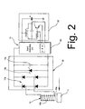
- rotation sensor 10 comprises a coil 12 that can be positioned in close proximity to the path of magnet 11, a rectifier 13 that rectifies current induced in coil 12 by movement of magnet 11 past coil 12, a signal generating unit 14 that operates using the rectified electrical power and generates rotation signals in accordance with the rotation of front wheel 105, and a wireless transmission unit 15 that wirelessly transmits the generated rotation signals.
- Coil 12, rectifier 13, signal generating unit 14 and wireless transmission unit 15 are housed inside sensor case 9.
- Coil 12 may comprise, for example, a copper wire winding 12b coiled around a ferrite core 12a.
- the shape of core 12a may be rod-like or some other shape.
- Rectifier 13 may comprise, for example, a full-wave rectifying diode bridge 13a that rectifies the electrical power generated by coil 12, a voltage regulating element in the form of a Zener diode 13b that regulates the voltage of the rectified electrical power from diode bridge 13a, and a capacitor 13c that smoothes the rectified and regulated electrical power.
- Signal generating unit 14 comprises, for example, a microcomputer (CPU) that operates using the electrical power from rectifier 13 and generates rotation signals according to the rotation of front wheel 105 using appropriate software.
- Wireless transmission unit 15 comprises, for example, a Hartley transmission circuit that wirelessly transmits the generated rotation signals as signals of a selected frequency of, for example, approximately 40 kHz.
- display control device 16 is mounted to the middle portion of handlebar 104.
- Display control device 16 includes a case 19 that is detachably mounted to a bracket 18 mounted to handlebar assembly 104.
- display control unit 20 Disposed within case 19 is display control unit 20 (Fig. 5) comprising a microcomputer that converts the rotation signals transmitted from rotation sensor 10 to speed information, distance information, and the like and displays the information to the rider.
- Display control device 16 also is connected to shift control devices 114a and 114b through respective input cables 119a and 119b to receive and display gear positions based on the gear position signals acquired by front gear position sensor 28 and rear gear position sensor 29.
- a wireless receiving unit 21 that receives the rotation signals transmitted by rotation sensor 10
- a display unit 22 such as a liquid crystal display that displays the various information
- a power supply 23 that provides operating power to display control unit 20
- a mode switch 24 for changing the display mode
- a selection switch 25 for making various selections
- the front gear position sensor 28 installed in front shift control device 114b
- the rear gear position sensor 29 installed in rear shift control device 114a
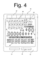
- other input/output units As shown in Fig. 4, mode switch 24 and selection switch 25 are physically positioned adjacent to each other at the lower front side of display unit 22.
- power supply 23 comprises a solar cell 27 and a storage element 26 that stores electrical power generated by solar cell 27.
- Solar cell 27 may be, for example, a known amorphous silicon type solar cell and may comprise, for example, 6 cells.
- Storage element 26 may be, for example, an electric double-layer capacitor or other high-capacity capacitor that can provide electrical power when solar cell 27 cannot generate sufficient electricity such as during the nighttime or during periods of inadequate sunlight. As shown in Fig. 4, solar cell 27 may be disposed on the upper front side of display unit 22.
- Fig. 4 also illustrates an embodiment of information that may be shown on a display screen 30 of display unit 22.
- display screen 30 comprises a segmented monochrome liquid crystal display screen that includes a main number display portion 32, a secondary number display portion 33, a description display portion 34, a rear gear position display portion 35, and a front gear position display portion 36.
- Information such as bicycle velocity, time, etc. is displayed in numerical format in main number display portion 32 and auxiliary number display portion 33.
- Description display portion 34 displays a description of the contents of main number display portion 32 and secondary number display portion 33.
- Rear gear position display portion 35 shows the gear position of rear transmission 109, and it comprises a plurality of, e.g., nine elliptical display symbols gradually decreasing in diameter from left to right to correspond with the size of the actual rear sprockets 143.
- the number of sprockets for rear transmission 109 can be set to match the actual number of sprockets installed on the bicycle. For example, when rear sprocket cluster 141 has eight sprockets, the number of rear sprockets 143 is input to the cycle computer. Thereafter, eight elliptical display symbols are displayed from left to right in rear gear position display portion 35, with the one remaining symbol at the right end not displayed.
- front gear position display portion 36 shows the gear position of front transmission 108, and it comprises a plurality of, e.g., three elliptical display symbols gradually increasing in diameter from left to right to correspond with the size of the actual front sprockets 137.
- the number of sprockets for front transmission 108 can be set to match the actual number of front sprockets 137 installed on the bicycle. For example, when front transmission 108 has two sprockets, the number of front sprockets 137 is input to the cycle computer. Thereafter, two elliptical display symbols are displayed from right to left in front gear position display portion 36, with the one remaining symbol at the left end not displayed.
- rear gear position display portion 35 and front gear position display portion 36 the sprocket positions of front and rear transmissions 108 and 109 may be ascertained intuitively at a glance.
- the transmitted rotation signals are received by wireless receiving unit 21 in display control device 16 and output to display control unit 20.
- the speed and riding distance of the bicycle are calculated by display control unit 20 from the interval between successive rotation signals and the diameter of the front wheel 105.
- the transmission gear positions are determined from the output of gear position sensors 28 and 29. These data are displayed in the designated sections of display unit 22. Since display control device 16 operates using the electrical power generated by solar cell 27, a separate power source requiring elaborate power conversion devices is unnecessary.
- rotation signals were generated by a microcomputer in rotation sensor 10, but an apparatus could be configured so that rotation signals are generated by analog or digital circuitry without the use of a microcomputer.
- solar cell 27 was used as the power source for display control device 16, a normal primary or secondary battery also could be used. In this case, a low-capacity electrolyte capacitor or other storage element could be provided for backup.
- rotation sensor 10 detected the rotation of front wheel 105 as a rotating part of the bicycle.
- a rotation sensor 210 could be used to detect the rotation of a left crank 236 of a bicycle 201.
- bicycle 201 includes a three-speed internal hub transmission mounted on the rear wheel.
- a magnet 211 may be mounted to left crank 236, and rotation sensor 210 (comprising a coil 12, rectifier 13, signal generating unit 14, and wireless transmission unit 15 as in the first embodiment) could be mounted on a frame 202 so that magnet 211 passes in close proximity as crank 236 rotates.
- the crank RPM could be displayed at display unit 22, and speed could be calculated using crank RPM, the current transmission gear and wheel RPM.
Landscapes
- Engineering & Computer Science (AREA)
- Computer Networks & Wireless Communication (AREA)
- Physics & Mathematics (AREA)
- General Physics & Mathematics (AREA)
- Arrangements For Transmission Of Measured Signals (AREA)
Applications Claiming Priority (2)
| Application Number | Priority Date | Filing Date | Title |
|---|---|---|---|
| JP2004013299A JP2005207820A (ja) | 2004-01-21 | 2004-01-21 | 自転車用信号出力装置及びそれを用いた自転車用走行状態表示システム |
| JP2004013299 | 2004-01-21 |
Publications (3)
| Publication Number | Publication Date |
|---|---|
| EP1560185A2 true EP1560185A2 (fr) | 2005-08-03 |
| EP1560185A3 EP1560185A3 (fr) | 2007-08-01 |
| EP1560185B1 EP1560185B1 (fr) | 2016-12-21 |
Family
ID=34650745
Family Applications (1)
| Application Number | Title | Priority Date | Filing Date |
|---|---|---|---|
| EP05001149.3A Expired - Lifetime EP1560185B1 (fr) | 2004-01-21 | 2005-01-20 | Dispositif auto-alimenté de sortie de signal pour une bicyclette et appareil d'affichage utilisant ledit dispositif |
Country Status (5)
| Country | Link |
|---|---|
| US (1) | US7253610B2 (fr) |
| EP (1) | EP1560185B1 (fr) |
| JP (1) | JP2005207820A (fr) |
| CN (1) | CN1645427A (fr) |
| TW (1) | TWI248589B (fr) |
Families Citing this family (19)
| Publication number | Priority date | Publication date | Assignee | Title |
|---|---|---|---|---|
| FR2887980B1 (fr) * | 2005-07-01 | 2007-09-28 | Commissariat Energie Atomique | Dispositif de comptage des rotations d'un objet dans un referentiel et procede de commande d'un tel dispositif |
| US7728583B2 (en) * | 2006-07-06 | 2010-06-01 | General Electric Company | Apparatus for monitoring rotary machines |
| US20080007145A1 (en) * | 2006-07-06 | 2008-01-10 | Yen-Yu Lin | Bicycle with at least one generator |
| US8035498B2 (en) * | 2006-08-15 | 2011-10-11 | Terry Pennisi | Wireless monitoring system with a self-powered transmitter |
| US7878521B2 (en) * | 2007-04-16 | 2011-02-01 | Trek Bicycle Corporation | Bicycle frame with device cavity |
| WO2009089225A1 (fr) * | 2008-01-07 | 2009-07-16 | Lelkendey, Steve | Système de surveillance sans fil possédant un émetteur-récepteur autoalimenté |
| US8384377B2 (en) * | 2009-10-30 | 2013-02-26 | Honeywell International Inc. | Self-powered magnetic tachometer for supplying a signal representative of rotational rate and absolute position |
| DE102010028428A1 (de) * | 2010-04-30 | 2011-11-03 | Siemens Aktiengesellschaft | Vorrichtung zur Umwandlung von Bewegungsenergie |
| US8378673B2 (en) * | 2010-11-09 | 2013-02-19 | Techway Industrial Co., Ltd. | Derailleur cable detecting assembly for an electric-auxiliary bicycle |
| WO2013165884A1 (fr) | 2012-04-30 | 2013-11-07 | Terry Pennisi | Émetteur sans fil collecteur d'énergie |
| US9991824B2 (en) | 2012-04-30 | 2018-06-05 | Terry Pennisi | Self powered optical system |
| US9304142B1 (en) * | 2013-03-12 | 2016-04-05 | A. Steve Gurganian | Energy harvesting zero-speed sensor device, method and system |
| JP2015027861A (ja) * | 2013-07-05 | 2015-02-12 | 株式会社シマノ | 自転車制御システム |
| US9581508B2 (en) * | 2015-01-23 | 2017-02-28 | Shimano Inc. | Bicycle pedaling force detector |
| ES1137557Y (es) * | 2015-03-04 | 2015-06-10 | Saez Juan Moya | Sensor de velocidad y cadencia de giro. |
| US10269249B2 (en) * | 2017-04-14 | 2019-04-23 | Shimano Inc. | Bicycle notification device including attaching portion, transmitter and power generator |
| CN108791656A (zh) * | 2018-06-28 | 2018-11-13 | 南京溧水电子研究所有限公司 | 适用于电动自行车的无源电子刹车装置 |
| EP3715858B1 (fr) * | 2019-03-28 | 2024-08-28 | The Swatch Group Research and Development Ltd | Procede et systeme de mesure d'au moins un parametre physique pour un velo |
| US11307106B2 (en) * | 2019-05-23 | 2022-04-19 | City University Of Hong Kong | Torque measurement system |
Citations (4)
| Publication number | Priority date | Publication date | Assignee | Title |
|---|---|---|---|---|
| JPH0312798A (ja) | 1989-06-10 | 1991-01-21 | Kiyatsuto I:Kk | 無線式送受信装置 |
| DE4229457A1 (de) | 1992-09-03 | 1994-03-10 | Renke Marken | Vorrichtung zur Stromerzeugung am Fahrrad |
| EP0645868A2 (fr) | 1993-09-24 | 1995-03-29 | Casio Computer Co., Ltd. | Appareil de charge |
| WO1996005999A1 (fr) | 1994-08-25 | 1996-02-29 | Leader Industries Inc. | Dispositif d'eclairage pour bicyclette |
Family Cites Families (17)
| Publication number | Priority date | Publication date | Assignee | Title |
|---|---|---|---|---|
| FR2308910A1 (fr) * | 1975-04-21 | 1976-11-19 | Genzling Claude | Dispositif compteur-tachymetre integre pour bicyclette |
| GB1554161A (en) * | 1976-10-21 | 1979-10-17 | Lucas Industries Ltd | Cycles |
| JPH067401Y2 (ja) | 1988-07-21 | 1994-02-23 | サムタク株式会社 | チップマウンタ用データ作成装置 |
| JPH0288972A (ja) | 1988-09-27 | 1990-03-29 | Shokichi Kumakura | 発電装置による自転車速度計 |
| US5008647A (en) | 1989-02-06 | 1991-04-16 | Orleander S.A. | Wireless bicycle wheel monitor system |
| DE4109006A1 (de) | 1991-03-19 | 1992-09-24 | Stefan E Metzner | An der antriebskette angetriebener stromgenerator (dynamo) fuer fahrraeder |
| US5177432A (en) | 1991-05-31 | 1993-01-05 | Ppg Industries, Inc. | Wireless velocity detector for a bicycle having a rotating AC magnetic field and receiver coils |
| DE4212321A1 (de) | 1992-04-13 | 1993-10-14 | Fichtel & Sachs Ag | Vorrichtung zur drahtlosen Signalübertragung |
| IT1266817B1 (it) | 1994-02-24 | 1997-01-21 | Campagnolo Srl | Dispositivo di cambio di velocita' per biciclette. |
| JPH08301175A (ja) | 1995-05-10 | 1996-11-19 | Yokohama Amenitei Kenkyusho:Kk | 無接点式信号伝送装置 |
| JPH0976982A (ja) | 1995-09-11 | 1997-03-25 | Yamaha Motor Co Ltd | パワーアシスト車両 |
| DE19604467A1 (de) | 1996-02-08 | 1997-08-14 | Rolf Wilhelm Haupt | System zur Erfassung, Übertragung und Anzeige von Daten |
| JPH09233793A (ja) | 1996-02-23 | 1997-09-05 | Pioneer Electron Corp | 自転車用発電装置 |
| FI100924B (fi) * | 1996-10-11 | 1998-03-13 | Polar Electro Oy | Telemetrinen mittausmenetelmä ja mittausjärjestelmä |
| JPH1120762A (ja) | 1997-06-27 | 1999-01-26 | Pioneer Electron Corp | 自転車用点灯装置 |
| JP2000152583A (ja) | 1999-08-28 | 2000-05-30 | Yoshio Hosomi | 自転車および自転車用発電部品 |
| DE20003309U1 (de) | 2000-02-23 | 2000-07-06 | Huang, Chun-Mu, Sanchung, Taipeh | Gehäusestruktur für eine Signalempfangs- und -übertragungseinrichtung |
-
2004
- 2004-01-21 JP JP2004013299A patent/JP2005207820A/ja active Pending
- 2004-12-23 TW TW093140306A patent/TWI248589B/zh not_active IP Right Cessation
-
2005
- 2005-01-19 US US10/905,748 patent/US7253610B2/en not_active Expired - Fee Related
- 2005-01-20 EP EP05001149.3A patent/EP1560185B1/fr not_active Expired - Lifetime
- 2005-01-21 CN CN200510004670.1A patent/CN1645427A/zh active Pending
Patent Citations (4)
| Publication number | Priority date | Publication date | Assignee | Title |
|---|---|---|---|---|
| JPH0312798A (ja) | 1989-06-10 | 1991-01-21 | Kiyatsuto I:Kk | 無線式送受信装置 |
| DE4229457A1 (de) | 1992-09-03 | 1994-03-10 | Renke Marken | Vorrichtung zur Stromerzeugung am Fahrrad |
| EP0645868A2 (fr) | 1993-09-24 | 1995-03-29 | Casio Computer Co., Ltd. | Appareil de charge |
| WO1996005999A1 (fr) | 1994-08-25 | 1996-02-29 | Leader Industries Inc. | Dispositif d'eclairage pour bicyclette |
Also Published As
| Publication number | Publication date |
|---|---|
| EP1560185B1 (fr) | 2016-12-21 |
| US7253610B2 (en) | 2007-08-07 |
| TW200527331A (en) | 2005-08-16 |
| CN1645427A (zh) | 2005-07-27 |
| JP2005207820A (ja) | 2005-08-04 |
| TWI248589B (en) | 2006-02-01 |
| US20050156590A1 (en) | 2005-07-21 |
| EP1560185A3 (fr) | 2007-08-01 |
Similar Documents
| Publication | Publication Date | Title |
|---|---|---|
| US7253610B2 (en) | Self-powered bicycle signal output device and display apparatus using same | |
| US12611940B2 (en) | Electric vehicle systems and methods for driving vehicles | |
| US7379798B2 (en) | Bicycle display apparatus with distributed processing | |
| TWI808359B (zh) | 用於電動輔助自行車之介面 | |
| USRE43562E1 (en) | Bicycle shift control apparatus that prevents undesirable chain angles | |
| US7288038B2 (en) | Bicycle shift control apparatus with preferential shifting | |
| CN100352725C (zh) | 自行车用信息处理装置 | |
| US8952793B2 (en) | Bicycle electrical system | |
| EP3088289B1 (fr) | Système de commande monté au centre d'une bicyclette | |
| US6959941B2 (en) | Bicycle shift control apparatus that selectively restricts speed stages | |
| US12240562B2 (en) | Derailleur for human-powered vehicle | |
| US20070296176A1 (en) | Bicycle shift control device that responds to a manually operated switch | |
| US20040113385A1 (en) | Bicycle electronic control device with a reset function | |
| US12595022B2 (en) | Bicycle control system | |
| CN108791689A (zh) | 自行车自动变速单元及包括该单元的自行车自动变速系统 | |
| JP2023119321A (ja) | 電動アシスト自転車の表示機 |
Legal Events
| Date | Code | Title | Description |
|---|---|---|---|
| PUAI | Public reference made under article 153(3) epc to a published international application that has entered the european phase |
Free format text: ORIGINAL CODE: 0009012 |
|
| AK | Designated contracting states |
Kind code of ref document: A2 Designated state(s): AT BE BG CH CY CZ DE DK EE ES FI FR GB GR HU IE IS IT LI LT LU MC NL PL PT RO SE SI SK TR |
|
| AX | Request for extension of the european patent |
Extension state: AL BA HR LV MK YU |
|
| RAP1 | Party data changed (applicant data changed or rights of an application transferred) |
Owner name: SHIMANO INC. |
|
| PUAL | Search report despatched |
Free format text: ORIGINAL CODE: 0009013 |
|
| AK | Designated contracting states |
Kind code of ref document: A3 Designated state(s): AT BE BG CH CY CZ DE DK EE ES FI FR GB GR HU IE IS IT LI LT LU MC NL PL PT RO SE SI SK TR |
|
| AX | Request for extension of the european patent |
Extension state: AL BA HR LV MK YU |
|
| 17P | Request for examination filed |
Effective date: 20070809 |
|
| AKX | Designation fees paid |
Designated state(s): DE FR IT NL |
|
| 17Q | First examination report despatched |
Effective date: 20080528 |
|
| GRAP | Despatch of communication of intention to grant a patent |
Free format text: ORIGINAL CODE: EPIDOSNIGR1 |
|
| INTG | Intention to grant announced |
Effective date: 20160916 |
|
| GRAS | Grant fee paid |
Free format text: ORIGINAL CODE: EPIDOSNIGR3 |
|
| GRAA | (expected) grant |
Free format text: ORIGINAL CODE: 0009210 |
|
| AK | Designated contracting states |
Kind code of ref document: B1 Designated state(s): DE FR IT NL |
|
| REG | Reference to a national code |
Ref country code: DE Ref legal event code: R096 Ref document number: 602005050931 Country of ref document: DE |
|
| REG | Reference to a national code |
Ref country code: NL Ref legal event code: MP Effective date: 20161221 |
|
| PG25 | Lapsed in a contracting state [announced via postgrant information from national office to epo] |
Ref country code: NL Free format text: LAPSE BECAUSE OF FAILURE TO SUBMIT A TRANSLATION OF THE DESCRIPTION OR TO PAY THE FEE WITHIN THE PRESCRIBED TIME-LIMIT Effective date: 20161221 |
|
| PGFP | Annual fee paid to national office [announced via postgrant information from national office to epo] |
Ref country code: IT Payment date: 20170329 Year of fee payment: 13 |
|
| REG | Reference to a national code |
Ref country code: DE Ref legal event code: R097 Ref document number: 602005050931 Country of ref document: DE |
|
| PLBE | No opposition filed within time limit |
Free format text: ORIGINAL CODE: 0009261 |
|
| REG | Reference to a national code |
Ref country code: FR Ref legal event code: ST Effective date: 20170929 |
|
| STAA | Information on the status of an ep patent application or granted ep patent |
Free format text: STATUS: NO OPPOSITION FILED WITHIN TIME LIMIT |
|
| PG25 | Lapsed in a contracting state [announced via postgrant information from national office to epo] |
Ref country code: FR Free format text: LAPSE BECAUSE OF NON-PAYMENT OF DUE FEES Effective date: 20170221 |
|
| 26N | No opposition filed |
Effective date: 20170922 |
|
| PG25 | Lapsed in a contracting state [announced via postgrant information from national office to epo] |
Ref country code: IT Free format text: LAPSE BECAUSE OF NON-PAYMENT OF DUE FEES Effective date: 20180120 |
|
| PGFP | Annual fee paid to national office [announced via postgrant information from national office to epo] |
Ref country code: DE Payment date: 20200121 Year of fee payment: 16 |
|
| REG | Reference to a national code |
Ref country code: DE Ref legal event code: R119 Ref document number: 602005050931 Country of ref document: DE |
|
| PG25 | Lapsed in a contracting state [announced via postgrant information from national office to epo] |
Ref country code: DE Free format text: LAPSE BECAUSE OF NON-PAYMENT OF DUE FEES Effective date: 20210803 |