EP1560899B1 - Ein Apparat mit einem Dichtungsmechismus, dem zwischen einem Festbrennstoffzufuhrsystem und einer Verbrennungskammer davon betrieben werden kann - Google Patents
Ein Apparat mit einem Dichtungsmechismus, dem zwischen einem Festbrennstoffzufuhrsystem und einer Verbrennungskammer davon betrieben werden kann Download PDFInfo
- Publication number
- EP1560899B1 EP1560899B1 EP03753628A EP03753628A EP1560899B1 EP 1560899 B1 EP1560899 B1 EP 1560899B1 EP 03753628 A EP03753628 A EP 03753628A EP 03753628 A EP03753628 A EP 03753628A EP 1560899 B1 EP1560899 B1 EP 1560899B1
- Authority
- EP
- European Patent Office
- Prior art keywords
- gate valve
- valve plate
- hopper
- feed system
- bottom end
- Prior art date
- Legal status (The legal status is an assumption and is not a legal conclusion. Google has not performed a legal analysis and makes no representation as to the accuracy of the status listed.)
- Expired - Lifetime
Links
Images

Classifications
-
- F—MECHANICAL ENGINEERING; LIGHTING; HEATING; WEAPONS; BLASTING
- F23—COMBUSTION APPARATUS; COMBUSTION PROCESSES
- F23K—FEEDING FUEL TO COMBUSTION APPARATUS
- F23K3/00—Feeding or distributing of lump or pulverulent fuel to combustion apparatus
- F23K3/16—Over-feed arrangements
-
- F—MECHANICAL ENGINEERING; LIGHTING; HEATING; WEAPONS; BLASTING
- F23—COMBUSTION APPARATUS; COMBUSTION PROCESSES
- F23G—CREMATION FURNACES; CONSUMING WASTE PRODUCTS BY COMBUSTION
- F23G5/00—Incineration of waste; Incinerator constructions; Details, accessories or control therefor
- F23G5/44—Details; Accessories
- F23G5/442—Waste feed arrangements
-
- C—CHEMISTRY; METALLURGY
- C10—PETROLEUM, GAS OR COKE INDUSTRIES; TECHNICAL GASES CONTAINING CARBON MONOXIDE; FUELS; LUBRICANTS; PEAT
- C10J—PRODUCTION OF PRODUCER GAS, WATER-GAS, SYNTHESIS GAS FROM SOLID CARBONACEOUS MATERIAL, OR MIXTURES CONTAINING THESE GASES; CARBURETTING AIR OR OTHER GASES
- C10J2200/00—Details of gasification apparatus
- C10J2200/09—Mechanical details of gasifiers not otherwise provided for, e.g. sealing means
-
- F—MECHANICAL ENGINEERING; LIGHTING; HEATING; WEAPONS; BLASTING
- F23—COMBUSTION APPARATUS; COMBUSTION PROCESSES
- F23G—CREMATION FURNACES; CONSUMING WASTE PRODUCTS BY COMBUSTION
- F23G2205/00—Waste feed arrangements
- F23G2205/14—Waste feed arrangements using hopper or bin
-
- F—MECHANICAL ENGINEERING; LIGHTING; HEATING; WEAPONS; BLASTING
- F23—COMBUSTION APPARATUS; COMBUSTION PROCESSES
- F23K—FEEDING FUEL TO COMBUSTION APPARATUS
- F23K2203/00—Feeding arrangements
- F23K2203/10—Supply line fittings
- F23K2203/102—Flashback safety, e.g. inertizing devices
Definitions
- the invention relates to a seal mechanism for a gate valve operable between a solid fuel feed system and a combustion space, such as a gasifier combustion chamber, the fuel feed system comprising a hopper having at least its bottom end portion shaped substantially cylindrical, whereby the gate valve controls the discharge opening of the feeder hopper bottom end, and the gate valve open/closed positions being controllable by means of a gate valve actuator mechanism in such a fashion that a seal is provided between the hopper bottom end and the gate valve.
- the combustion space such as the combustion chamber of a gas generator and the portion of the fuel feed system downstream of the fuel feed point generally need to be isolated from each other for process control and safety reasons.
- This kind of isolation is frequently complicated since fuel residues such as chips, peat clumps or the like objects may remain on the sealing surfaces, whereby safe sealing is problematic.
- the high temperature in the combustion chamber sets high demands on the sealing arrangement.
- Conventional gate valves generally operate hingedly so that the gate plate is rotated downward to open and respectively upward to close the gate valve. Then, at the closure of the gate valve, residues of solid fuel may remain between the gate valve and its seat surface. As a result, the gate valve fails to close tightly.
- Document GB-A-1447628 discloses a slide valve plate below a hopper for regulating the flow material from it.
- the valve is held in position by upward pressure using a P-actuated switch with release of pressure being used to open the slide valve.
- the lower end of the hopper is provided with a scrabing member which makes contact with the sliding plate to close the hopper.
- This sealing arrangement could not be used with combustion spaces, because the sealing member consists of a polyurethane rubber moulding. The seal would not last the very hot conditions of combustion spaces.
- the sealing arrangement according to the invention is characterized in that the lower edge of hopper is provided with a sealing member whose edge facing the gate valve plate is annular and is sharpened substantially over its entire circumferential length, and that when opening the gate valve plate it is first lowered slightly downward from its closed position and thereupon rotated aside so as to uncovered the discharge opening at the feeder hopper and that the closure of the gate valve plate is adapted to take place in reverse order, and that the sealing member is made from a metal.
- sealing member is a seal ring detachably mounted to the bottom portion of the hopper.
- a still further another sealing arrangement according to the invention is characterized in that the movement of the gate valve plate, is carried out with the help of its actuator mechanism.
- the invention is further characterized in that, in the opening direction of gate valve, in a close vicinity of the seal ring is mounted a doctor blade adapted to sweep the top surface of the gate valve plate clean from debris as the gate valve plate passes under the doctor blade.
- a benefit of the invention is that any fuel residue possibly remaining between the gate valve plate and the sealing member edge is cut into pieces by the sharp edge of the sealing member, whereby the gate valve can close tightly.
- the gate valve plate is moved hydraulically thus allowing a sufficient force to be imposed thereon for cutting any solid fuel clumps possibly jamming the gate valve.
- a solid fuel hopper that has its bottom portion made at least partially cylindrical and is adapted to feed fuel further into a combustion space 2.
- a gate valve 3 that can be driven closed so as to cover the cylindrical bottom opening of the hopper.
- the function of gate valve 3 is to provide sealed isolation of the fuel feed system from the combustion space.
- annular seal member 4 To the bottom portion of the hopper is made or attached an annular seal member whose lower edge tapers downward so as to form a sharp annular cutting rim in cooperation with gate valve plate 3.
- seal member 4 As the seal member 4 is metallic, it offers an extremely good service life in regard to conventional seals. By way of using a dismountable annular seal as the seal member, the seal can be removed for resharpening when necessary.
- reference numerals 5 and 6 designate the actuator mechanism of gate valve plate 3 employed for opening and closing the gate valve.
- gate valve 3 is shown in its closed position in which the sharp edge of the annular seal member 4 faces gate valve plate 3.
- the gate valve plate is first lowered by the gate valve actuator mechanism 5, 6 slightly apart from the annular seal member 4 as shown in FIG. 2 .
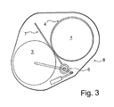
- the same mechanism performs the rotation of the gate valve into the position shown in FIG 3 , wherein the gate valve is entirely removed from below hopper 1 thus allowing the solid fuel to fall from hopper 1 into combustion space 3.
- the gate valve plate is rotated from the horizontal position of FIG. 2 to a closing position below feeder hopper 1. Also during this movement, doctor blade 7 cleans the top surface of gate valve plate 3.
- the gate valve plate is elevated against the annular sealing member 4 applying a vigorous force exerted by hydraulical means, for instance, such that any possible debris still adhering to the gate valve plate top surface is cut apart by the sharp edge of the annular sealing member thus permitting sealed closure of the gate valve.
Landscapes
- Engineering & Computer Science (AREA)
- Mechanical Engineering (AREA)
- General Engineering & Computer Science (AREA)
- Environmental & Geological Engineering (AREA)
- Chemical & Material Sciences (AREA)
- Combustion & Propulsion (AREA)
- Portable Nailing Machines And Staplers (AREA)
- Combustion Methods Of Internal-Combustion Engines (AREA)
- Filling Or Emptying Of Bunkers, Hoppers, And Tanks (AREA)
Claims (4)
- Vorrichtung, umfassend die Kombination eines Dichtungsmechanismus umfassend eine Absperrventilplatte (3), welche zwischen einem Festbrennstoff Zuführsystem (1) und einem Verbrennungsraum (2), wie einer Gaserzeuger-Verbrennungskammer, betriebsfähig ist, wobei das Brennstoff-Zuführsystem einen Behälter (1) umfasst, bei welchem zumindest sein Bodenendabschnitt im wesentlichen zylindrisch geformt ist, wobei die Absperrventilplatte (3) die Abgabeöffnung des Behälterbodenendes steuert und die Öffnungs-/Schliess-Stellungen der Absperrventilplatte mittels eines Absperrventil-Aktuatormechanismus (5, 6) in solch einer Weise steuerbar sind, dass eine Abdichtung zwischen dem Bodenende des Behälters (1) und der Absperrventilplatte (3) vorgesehen wird, dadurch gekennzeichnet, dass die untere Kante des Behälters (1) mit einem Dichtelement (4) versehen ist, dessen auf die Absperrventilplatte (3) weisende Kante ringförmig und im wesentlichen über ihre gesamte Umfangslänge geschärft ist und wobei der Aktuatormechanismus (5, 6) derart ausgelegt ist, dass, wenn dieser die Absperrventilplatte (3) öffnet, sie ausgehend von ihrer geschlossenen Stellung zunächst geringfügig nach unten gesenkt und daraufhin zur Seite gedreht wird, und dass das Schliessen der Absperrventilplatte geeignet ist, in umgekehrter Reihenfolge stattzufinden, und dass das Dichtungselement aus Metall hergestellt ist
- Vorrichtung nach Anspruch 1, dadurch gekennzeichnet, dass das Dichtungselement (4) ein Dichtungsring ist, welcher abnehmbar an dem Bodenabschnitt des Gefässes angebracht ist.
- Vorrichtung nach irgendeinem der Ansprüche 1 und 2, dadurch gekennzeichnet, dass die Bewegung der Absperrventilplatte (3) mit Hilfe ihres Aktuatormechanismus (5, 6) ausgeführt wird
- Vorrichtung nach irgendeinem der Ansprüche 1 bis 3, dadurch gekennzeichnet, dass in der Öffnungsrichtung des Absperrventils (3) in einer nahen Umgebung des Dichtungsrings (4) ein Abstreifmesser (7) angebracht ist, welches geeignet ist, die obere Oberfläche der Absperrventilplatte frei von Ablagerungen abzukehren, wenn die Absperrventilplatte unter dem Abstreifmesser hindurchläuft
Applications Claiming Priority (3)
| Application Number | Priority Date | Filing Date | Title |
|---|---|---|---|
| FI20021945A FI113782B (fi) | 2002-11-01 | 2002-11-01 | Kiinteän polttoaineen syöttöjärjestelmän ja palotilan välisen luukun tiivistys |
| FI20021945 | 2002-11-01 | ||
| PCT/FI2003/000779 WO2004039923A1 (en) | 2002-11-01 | 2003-10-21 | Seal mechanism operable between a solid fuel feed system and combustion chamber thereof |
Publications (2)
| Publication Number | Publication Date |
|---|---|
| EP1560899A1 EP1560899A1 (de) | 2005-08-10 |
| EP1560899B1 true EP1560899B1 (de) | 2009-07-22 |
Family
ID=8564857
Family Applications (1)
| Application Number | Title | Priority Date | Filing Date |
|---|---|---|---|
| EP03753628A Expired - Lifetime EP1560899B1 (de) | 2002-11-01 | 2003-10-21 | Ein Apparat mit einem Dichtungsmechismus, dem zwischen einem Festbrennstoffzufuhrsystem und einer Verbrennungskammer davon betrieben werden kann |
Country Status (7)
| Country | Link |
|---|---|
| EP (1) | EP1560899B1 (de) |
| JP (1) | JP2006504923A (de) |
| AT (1) | ATE437212T1 (de) |
| AU (1) | AU2003271793A1 (de) |
| DE (1) | DE60328510D1 (de) |
| FI (1) | FI113782B (de) |
| WO (1) | WO2004039923A1 (de) |
Families Citing this family (5)
| Publication number | Priority date | Publication date | Assignee | Title |
|---|---|---|---|---|
| US10071863B2 (en) | 2013-03-15 | 2018-09-11 | Mark E. Koenig | Method for processing material for a gasifier |
| US10190065B2 (en) | 2013-03-15 | 2019-01-29 | Mark E. Koenig | Feed delivery system and method for gasifier |
| GB2516122B (en) * | 2013-03-15 | 2016-03-23 | Mark Koenig | Isolation Gate |
| CN106568103A (zh) * | 2016-11-08 | 2017-04-19 | 惠州市欧野科技有限公司 | 一种节能炉 |
| KR102867931B1 (ko) * | 2024-12-24 | 2025-10-01 | 리뉴에너지그린 주식회사 | 소각로용 호퍼 수평 게이트 구조 |
Family Cites Families (3)
| Publication number | Priority date | Publication date | Assignee | Title |
|---|---|---|---|---|
| GB806752A (en) * | 1956-04-03 | 1958-12-31 | Power Gas Ltd | Improvements in or relating to charging devices for shaft furnaces or the like |
| GB1436555A (en) * | 1972-09-01 | 1976-05-19 | F R Eng Co Ltd | Valve forfluent material |
| GB1447628A (en) * | 1972-12-13 | 1976-08-25 | F R Eng Co Ltd | Seal especially for gate-type slide valves |
-
2002
- 2002-11-01 FI FI20021945A patent/FI113782B/fi active
-
2003
- 2003-10-21 JP JP2004547677A patent/JP2006504923A/ja active Pending
- 2003-10-21 DE DE60328510T patent/DE60328510D1/de not_active Expired - Fee Related
- 2003-10-21 WO PCT/FI2003/000779 patent/WO2004039923A1/en not_active Ceased
- 2003-10-21 AT AT03753628T patent/ATE437212T1/de not_active IP Right Cessation
- 2003-10-21 EP EP03753628A patent/EP1560899B1/de not_active Expired - Lifetime
- 2003-10-21 AU AU2003271793A patent/AU2003271793A1/en not_active Abandoned
Also Published As
| Publication number | Publication date |
|---|---|
| DE60328510D1 (de) | 2009-09-03 |
| JP2006504923A (ja) | 2006-02-09 |
| WO2004039923A1 (en) | 2004-05-13 |
| FI113782B (fi) | 2004-06-15 |
| FI20021945A0 (fi) | 2002-11-01 |
| ATE437212T1 (de) | 2009-08-15 |
| EP1560899A1 (de) | 2005-08-10 |
| AU2003271793A1 (en) | 2004-05-25 |
Similar Documents
| Publication | Publication Date | Title |
|---|---|---|
| US6989081B2 (en) | Valve system and method for unheading a coke drum | |
| RU2300549C2 (ru) | Клапан и система дросселирования нижней крышки коксового барабана | |
| NO330605B1 (no) | Styringsventil. | |
| US4505292A (en) | Valve for abrasive mixtures | |
| EP1560899A1 (de) | Dichtungsmechanismus, der zwischen einem festbrennstoffzufuhrsystem und einer verbrennungskammer davon betrieben werden kann | |
| EA002473B1 (ru) | Предохранительное устройство для аппарата для газирования жидкости | |
| GB1600032A (en) | Pressure cooker relief valve assebmly and pressure cookers incorporating such assemblies | |
| US4033730A (en) | Process and apparatus for feeding particulate solids into a pressure reactor | |
| SU1215627A3 (ru) | Уплотнительное устройство дл заслонки загрузочной камеры напорного дефибрера непрерывного действи | |
| US2925334A (en) | Pressure closure valve | |
| US11484854B2 (en) | Closure device for a bulk materials system | |
| EP0172053A1 (de) | Selbstreinigende Ventile für pulverige, körnige und teigartige Produkte | |
| BR0111660A (pt) | Válvula de fechamento estanque a gás | |
| CA1162876A (en) | Gastight closure | |
| US1723264A (en) | Gate valve | |
| US3064673A (en) | Pressure relief valve for pressurized containers | |
| WO1993010950A1 (en) | Positionable plate used as a valve for controlling liquid-jet cutting | |
| US3126028A (en) | Seal for bleeder valves | |
| NO830273L (no) | Ventiltetning. | |
| US2590620A (en) | Safety and release valve for pressure cookers | |
| US3430011A (en) | Auger corner with relief and shutoff switch | |
| CN205315719U (zh) | 一种凸轮杠杆快启阀门 | |
| GB1600031A (en) | Pressure cooker relief valve assembly and pressure cookers incorporating such assemblies | |
| SU1125264A1 (ru) | Устройство дл подачи сыпучих материалов | |
| SU1346512A1 (ru) | Затвор дл сыпучих материалов |
Legal Events
| Date | Code | Title | Description |
|---|---|---|---|
| PUAI | Public reference made under article 153(3) epc to a published international application that has entered the european phase |
Free format text: ORIGINAL CODE: 0009012 |
|
| 17P | Request for examination filed |
Effective date: 20050418 |
|
| AK | Designated contracting states |
Kind code of ref document: A1 Designated state(s): AT BE BG CH CY CZ DE DK EE ES FI FR GB GR HU IE IT LI LU MC NL PT RO SE SI SK TR |
|
| AX | Request for extension of the european patent |
Extension state: AL LT LV MK |
|
| DAX | Request for extension of the european patent (deleted) | ||
| 17Q | First examination report despatched |
Effective date: 20061207 |
|
| RTI1 | Title (correction) |
Free format text: AN APPARATUS WITH A SEAL MECHANISM OPERABLE BETWEEN A SOILD FUEL FEED SYSTEM AND A COMBUSTION CHAMBER THEREOF |
|
| GRAP | Despatch of communication of intention to grant a patent |
Free format text: ORIGINAL CODE: EPIDOSNIGR1 |
|
| RIC1 | Information provided on ipc code assigned before grant |
Ipc: C10J 3/00 20060101AFI20090122BHEP Ipc: C10B 25/16 20060101ALN20090122BHEP |
|
| GRAS | Grant fee paid |
Free format text: ORIGINAL CODE: EPIDOSNIGR3 |
|
| GRAA | (expected) grant |
Free format text: ORIGINAL CODE: 0009210 |
|
| AK | Designated contracting states |
Kind code of ref document: B1 Designated state(s): AT BE BG CH CY CZ DE DK EE ES FI FR GB GR HU IE IT LI LU MC NL PT RO SE SI SK TR |
|
| REG | Reference to a national code |
Ref country code: GB Ref legal event code: FG4D |
|
| REG | Reference to a national code |
Ref country code: CH Ref legal event code: EP |
|
| REG | Reference to a national code |
Ref country code: IE Ref legal event code: FG4D |
|
| REF | Corresponds to: |
Ref document number: 60328510 Country of ref document: DE Date of ref document: 20090903 Kind code of ref document: P |
|
| NLV1 | Nl: lapsed or annulled due to failure to fulfill the requirements of art. 29p and 29m of the patents act | ||
| PG25 | Lapsed in a contracting state [announced via postgrant information from national office to epo] |
Ref country code: SE Free format text: LAPSE BECAUSE OF FAILURE TO SUBMIT A TRANSLATION OF THE DESCRIPTION OR TO PAY THE FEE WITHIN THE PRESCRIBED TIME-LIMIT Effective date: 20090722 Ref country code: AT Free format text: LAPSE BECAUSE OF FAILURE TO SUBMIT A TRANSLATION OF THE DESCRIPTION OR TO PAY THE FEE WITHIN THE PRESCRIBED TIME-LIMIT Effective date: 20090722 Ref country code: FI Free format text: LAPSE BECAUSE OF FAILURE TO SUBMIT A TRANSLATION OF THE DESCRIPTION OR TO PAY THE FEE WITHIN THE PRESCRIBED TIME-LIMIT Effective date: 20090722 Ref country code: ES Free format text: LAPSE BECAUSE OF FAILURE TO SUBMIT A TRANSLATION OF THE DESCRIPTION OR TO PAY THE FEE WITHIN THE PRESCRIBED TIME-LIMIT Effective date: 20091102 |
|
| PG25 | Lapsed in a contracting state [announced via postgrant information from national office to epo] |
Ref country code: NL Free format text: LAPSE BECAUSE OF FAILURE TO SUBMIT A TRANSLATION OF THE DESCRIPTION OR TO PAY THE FEE WITHIN THE PRESCRIBED TIME-LIMIT Effective date: 20090722 Ref country code: SI Free format text: LAPSE BECAUSE OF FAILURE TO SUBMIT A TRANSLATION OF THE DESCRIPTION OR TO PAY THE FEE WITHIN THE PRESCRIBED TIME-LIMIT Effective date: 20090722 |
|
| PG25 | Lapsed in a contracting state [announced via postgrant information from national office to epo] |
Ref country code: PT Free format text: LAPSE BECAUSE OF FAILURE TO SUBMIT A TRANSLATION OF THE DESCRIPTION OR TO PAY THE FEE WITHIN THE PRESCRIBED TIME-LIMIT Effective date: 20091122 Ref country code: BG Free format text: LAPSE BECAUSE OF FAILURE TO SUBMIT A TRANSLATION OF THE DESCRIPTION OR TO PAY THE FEE WITHIN THE PRESCRIBED TIME-LIMIT Effective date: 20091022 |
|
| PG25 | Lapsed in a contracting state [announced via postgrant information from national office to epo] |
Ref country code: EE Free format text: LAPSE BECAUSE OF FAILURE TO SUBMIT A TRANSLATION OF THE DESCRIPTION OR TO PAY THE FEE WITHIN THE PRESCRIBED TIME-LIMIT Effective date: 20090722 Ref country code: CZ Free format text: LAPSE BECAUSE OF FAILURE TO SUBMIT A TRANSLATION OF THE DESCRIPTION OR TO PAY THE FEE WITHIN THE PRESCRIBED TIME-LIMIT Effective date: 20090722 Ref country code: RO Free format text: LAPSE BECAUSE OF FAILURE TO SUBMIT A TRANSLATION OF THE DESCRIPTION OR TO PAY THE FEE WITHIN THE PRESCRIBED TIME-LIMIT Effective date: 20090722 Ref country code: DK Free format text: LAPSE BECAUSE OF FAILURE TO SUBMIT A TRANSLATION OF THE DESCRIPTION OR TO PAY THE FEE WITHIN THE PRESCRIBED TIME-LIMIT Effective date: 20090722 |
|
| PLBE | No opposition filed within time limit |
Free format text: ORIGINAL CODE: 0009261 |
|
| STAA | Information on the status of an ep patent application or granted ep patent |
Free format text: STATUS: NO OPPOSITION FILED WITHIN TIME LIMIT |
|
| PG25 | Lapsed in a contracting state [announced via postgrant information from national office to epo] |
Ref country code: MC Free format text: LAPSE BECAUSE OF NON-PAYMENT OF DUE FEES Effective date: 20091031 Ref country code: SK Free format text: LAPSE BECAUSE OF FAILURE TO SUBMIT A TRANSLATION OF THE DESCRIPTION OR TO PAY THE FEE WITHIN THE PRESCRIBED TIME-LIMIT Effective date: 20090722 Ref country code: BE Free format text: LAPSE BECAUSE OF FAILURE TO SUBMIT A TRANSLATION OF THE DESCRIPTION OR TO PAY THE FEE WITHIN THE PRESCRIBED TIME-LIMIT Effective date: 20090722 |
|
| REG | Reference to a national code |
Ref country code: CH Ref legal event code: PL |
|
| 26N | No opposition filed |
Effective date: 20100423 |
|
| REG | Reference to a national code |
Ref country code: FR Ref legal event code: ST Effective date: 20100630 |
|
| PG25 | Lapsed in a contracting state [announced via postgrant information from national office to epo] |
Ref country code: FR Free format text: LAPSE BECAUSE OF NON-PAYMENT OF DUE FEES Effective date: 20091102 Ref country code: DE Free format text: LAPSE BECAUSE OF NON-PAYMENT OF DUE FEES Effective date: 20100501 |
|
| PG25 | Lapsed in a contracting state [announced via postgrant information from national office to epo] |
Ref country code: CH Free format text: LAPSE BECAUSE OF NON-PAYMENT OF DUE FEES Effective date: 20091031 Ref country code: GR Free format text: LAPSE BECAUSE OF FAILURE TO SUBMIT A TRANSLATION OF THE DESCRIPTION OR TO PAY THE FEE WITHIN THE PRESCRIBED TIME-LIMIT Effective date: 20091023 Ref country code: IE Free format text: LAPSE BECAUSE OF NON-PAYMENT OF DUE FEES Effective date: 20091021 Ref country code: LI Free format text: LAPSE BECAUSE OF NON-PAYMENT OF DUE FEES Effective date: 20091031 |
|
| PG25 | Lapsed in a contracting state [announced via postgrant information from national office to epo] |
Ref country code: GB Free format text: LAPSE BECAUSE OF NON-PAYMENT OF DUE FEES Effective date: 20091022 |
|
| PG25 | Lapsed in a contracting state [announced via postgrant information from national office to epo] |
Ref country code: IT Free format text: LAPSE BECAUSE OF FAILURE TO SUBMIT A TRANSLATION OF THE DESCRIPTION OR TO PAY THE FEE WITHIN THE PRESCRIBED TIME-LIMIT Effective date: 20090722 |
|
| PG25 | Lapsed in a contracting state [announced via postgrant information from national office to epo] |
Ref country code: LU Free format text: LAPSE BECAUSE OF NON-PAYMENT OF DUE FEES Effective date: 20091021 |
|
| PG25 | Lapsed in a contracting state [announced via postgrant information from national office to epo] |
Ref country code: HU Free format text: LAPSE BECAUSE OF FAILURE TO SUBMIT A TRANSLATION OF THE DESCRIPTION OR TO PAY THE FEE WITHIN THE PRESCRIBED TIME-LIMIT Effective date: 20100123 |
|
| PG25 | Lapsed in a contracting state [announced via postgrant information from national office to epo] |
Ref country code: TR Free format text: LAPSE BECAUSE OF FAILURE TO SUBMIT A TRANSLATION OF THE DESCRIPTION OR TO PAY THE FEE WITHIN THE PRESCRIBED TIME-LIMIT Effective date: 20090722 |
|
| PG25 | Lapsed in a contracting state [announced via postgrant information from national office to epo] |
Ref country code: CY Free format text: LAPSE BECAUSE OF FAILURE TO SUBMIT A TRANSLATION OF THE DESCRIPTION OR TO PAY THE FEE WITHIN THE PRESCRIBED TIME-LIMIT Effective date: 20090722 |