EP1561015B1 - Procede de nettoyage d'un filtre a particules et vehicule exploitant ce procede - Google Patents
Procede de nettoyage d'un filtre a particules et vehicule exploitant ce procede Download PDFInfo
- Publication number
- EP1561015B1 EP1561015B1 EP03754335A EP03754335A EP1561015B1 EP 1561015 B1 EP1561015 B1 EP 1561015B1 EP 03754335 A EP03754335 A EP 03754335A EP 03754335 A EP03754335 A EP 03754335A EP 1561015 B1 EP1561015 B1 EP 1561015B1
- Authority
- EP
- European Patent Office
- Prior art keywords
- exhaust
- fuel
- particle filter
- internal combustion
- combustion engine
- Prior art date
- Legal status (The legal status is an assumption and is not a legal conclusion. Google has not performed a legal analysis and makes no representation as to the accuracy of the status listed.)
- Expired - Lifetime
Links
Images


Classifications
-
- F—MECHANICAL ENGINEERING; LIGHTING; HEATING; WEAPONS; BLASTING
- F02—COMBUSTION ENGINES; HOT-GAS OR COMBUSTION-PRODUCT ENGINE PLANTS
- F02D—CONTROLLING COMBUSTION ENGINES
- F02D41/00—Electrical control of supply of combustible mixture or its constituents
- F02D41/30—Controlling fuel injection
- F02D41/38—Controlling fuel injection of the high pressure type
- F02D41/40—Controlling fuel injection of the high pressure type with means for controlling injection timing or duration
- F02D41/402—Multiple injections
- F02D41/405—Multiple injections with post injections
-
- F—MECHANICAL ENGINEERING; LIGHTING; HEATING; WEAPONS; BLASTING
- F01—MACHINES OR ENGINES IN GENERAL; ENGINE PLANTS IN GENERAL; STEAM ENGINES
- F01N—GAS-FLOW SILENCERS OR EXHAUST APPARATUS FOR MACHINES OR ENGINES IN GENERAL; GAS-FLOW SILENCERS OR EXHAUST APPARATUS FOR INTERNAL-COMBUSTION ENGINES
- F01N13/00—Exhaust or silencing apparatus characterised by constructional features
- F01N13/009—Exhaust or silencing apparatus characterised by constructional features having two or more separate purifying devices arranged in series
- F01N13/0097—Exhaust or silencing apparatus characterised by constructional features having two or more separate purifying devices arranged in series the purifying devices are arranged in a single housing
-
- F—MECHANICAL ENGINEERING; LIGHTING; HEATING; WEAPONS; BLASTING
- F01—MACHINES OR ENGINES IN GENERAL; ENGINE PLANTS IN GENERAL; STEAM ENGINES
- F01N—GAS-FLOW SILENCERS OR EXHAUST APPARATUS FOR MACHINES OR ENGINES IN GENERAL; GAS-FLOW SILENCERS OR EXHAUST APPARATUS FOR INTERNAL-COMBUSTION ENGINES
- F01N3/00—Exhaust or silencing apparatus having means for purifying, rendering innocuous, or otherwise treating exhaust
- F01N3/02—Exhaust or silencing apparatus having means for purifying, rendering innocuous, or otherwise treating exhaust for cooling, or for removing solid constituents of, exhaust
- F01N3/021—Exhaust or silencing apparatus having means for purifying, rendering innocuous, or otherwise treating exhaust for cooling, or for removing solid constituents of, exhaust by means of filters
- F01N3/023—Exhaust or silencing apparatus having means for purifying, rendering innocuous, or otherwise treating exhaust for cooling, or for removing solid constituents of, exhaust by means of filters using means for regenerating the filters, e.g. by burning trapped particles
- F01N3/025—Exhaust or silencing apparatus having means for purifying, rendering innocuous, or otherwise treating exhaust for cooling, or for removing solid constituents of, exhaust by means of filters using means for regenerating the filters, e.g. by burning trapped particles using fuel burner or by adding fuel to exhaust
- F01N3/0253—Exhaust or silencing apparatus having means for purifying, rendering innocuous, or otherwise treating exhaust for cooling, or for removing solid constituents of, exhaust by means of filters using means for regenerating the filters, e.g. by burning trapped particles using fuel burner or by adding fuel to exhaust adding fuel to exhaust gases
-
- F—MECHANICAL ENGINEERING; LIGHTING; HEATING; WEAPONS; BLASTING
- F01—MACHINES OR ENGINES IN GENERAL; ENGINE PLANTS IN GENERAL; STEAM ENGINES
- F01N—GAS-FLOW SILENCERS OR EXHAUST APPARATUS FOR MACHINES OR ENGINES IN GENERAL; GAS-FLOW SILENCERS OR EXHAUST APPARATUS FOR INTERNAL-COMBUSTION ENGINES
- F01N3/00—Exhaust or silencing apparatus having means for purifying, rendering innocuous, or otherwise treating exhaust
- F01N3/02—Exhaust or silencing apparatus having means for purifying, rendering innocuous, or otherwise treating exhaust for cooling, or for removing solid constituents of, exhaust
- F01N3/021—Exhaust or silencing apparatus having means for purifying, rendering innocuous, or otherwise treating exhaust for cooling, or for removing solid constituents of, exhaust by means of filters
- F01N3/033—Exhaust or silencing apparatus having means for purifying, rendering innocuous, or otherwise treating exhaust for cooling, or for removing solid constituents of, exhaust by means of filters in combination with other devices
- F01N3/035—Exhaust or silencing apparatus having means for purifying, rendering innocuous, or otherwise treating exhaust for cooling, or for removing solid constituents of, exhaust by means of filters in combination with other devices with catalytic reactors
-
- F—MECHANICAL ENGINEERING; LIGHTING; HEATING; WEAPONS; BLASTING
- F02—COMBUSTION ENGINES; HOT-GAS OR COMBUSTION-PRODUCT ENGINE PLANTS
- F02B—INTERNAL-COMBUSTION PISTON ENGINES; COMBUSTION ENGINES IN GENERAL
- F02B29/00—Engines characterised by provision for charging or scavenging not provided for in groups F02B25/00, F02B27/00 or F02B33/00 - F02B39/00; Details thereof
- F02B29/04—Cooling of air intake supply
-
- F—MECHANICAL ENGINEERING; LIGHTING; HEATING; WEAPONS; BLASTING
- F02—COMBUSTION ENGINES; HOT-GAS OR COMBUSTION-PRODUCT ENGINE PLANTS
- F02B—INTERNAL-COMBUSTION PISTON ENGINES; COMBUSTION ENGINES IN GENERAL
- F02B37/00—Engines characterised by provision of pumps driven at least for part of the time by exhaust
- F02B37/12—Control of the pumps
- F02B37/22—Control of the pumps by varying cross-section of exhaust passages or air passages, e.g. by throttling turbine inlets or outlets or by varying effective number of guide conduits
-
- F—MECHANICAL ENGINEERING; LIGHTING; HEATING; WEAPONS; BLASTING
- F02—COMBUSTION ENGINES; HOT-GAS OR COMBUSTION-PRODUCT ENGINE PLANTS
- F02D—CONTROLLING COMBUSTION ENGINES
- F02D41/00—Electrical control of supply of combustible mixture or its constituents
- F02D41/02—Circuit arrangements for generating control signals
- F02D41/021—Introducing corrections for particular conditions exterior to the engine
- F02D41/0235—Introducing corrections for particular conditions exterior to the engine in relation with the state of the exhaust gas treating apparatus
- F02D41/024—Introducing corrections for particular conditions exterior to the engine in relation with the state of the exhaust gas treating apparatus to increase temperature of the exhaust gas treating apparatus
- F02D41/025—Introducing corrections for particular conditions exterior to the engine in relation with the state of the exhaust gas treating apparatus to increase temperature of the exhaust gas treating apparatus by changing the composition of the exhaust gas, e.g. for exothermic reaction on exhaust gas treating apparatus
-
- F—MECHANICAL ENGINEERING; LIGHTING; HEATING; WEAPONS; BLASTING
- F02—COMBUSTION ENGINES; HOT-GAS OR COMBUSTION-PRODUCT ENGINE PLANTS
- F02D—CONTROLLING COMBUSTION ENGINES
- F02D41/00—Electrical control of supply of combustible mixture or its constituents
- F02D41/02—Circuit arrangements for generating control signals
- F02D41/021—Introducing corrections for particular conditions exterior to the engine
- F02D41/0235—Introducing corrections for particular conditions exterior to the engine in relation with the state of the exhaust gas treating apparatus
- F02D41/027—Introducing corrections for particular conditions exterior to the engine in relation with the state of the exhaust gas treating apparatus to purge or regenerate the exhaust gas treating apparatus
- F02D41/029—Introducing corrections for particular conditions exterior to the engine in relation with the state of the exhaust gas treating apparatus to purge or regenerate the exhaust gas treating apparatus the exhaust gas treating apparatus being a particulate filter
-
- F—MECHANICAL ENGINEERING; LIGHTING; HEATING; WEAPONS; BLASTING
- F02—COMBUSTION ENGINES; HOT-GAS OR COMBUSTION-PRODUCT ENGINE PLANTS
- F02B—INTERNAL-COMBUSTION PISTON ENGINES; COMBUSTION ENGINES IN GENERAL
- F02B37/00—Engines characterised by provision of pumps driven at least for part of the time by exhaust
-
- Y—GENERAL TAGGING OF NEW TECHNOLOGICAL DEVELOPMENTS; GENERAL TAGGING OF CROSS-SECTIONAL TECHNOLOGIES SPANNING OVER SEVERAL SECTIONS OF THE IPC; TECHNICAL SUBJECTS COVERED BY FORMER USPC CROSS-REFERENCE ART COLLECTIONS [XRACs] AND DIGESTS
- Y02—TECHNOLOGIES OR APPLICATIONS FOR MITIGATION OR ADAPTATION AGAINST CLIMATE CHANGE
- Y02T—CLIMATE CHANGE MITIGATION TECHNOLOGIES RELATED TO TRANSPORTATION
- Y02T10/00—Road transport of goods or passengers
- Y02T10/10—Internal combustion engine [ICE] based vehicles
- Y02T10/12—Improving ICE efficiencies
-
- Y—GENERAL TAGGING OF NEW TECHNOLOGICAL DEVELOPMENTS; GENERAL TAGGING OF CROSS-SECTIONAL TECHNOLOGIES SPANNING OVER SEVERAL SECTIONS OF THE IPC; TECHNICAL SUBJECTS COVERED BY FORMER USPC CROSS-REFERENCE ART COLLECTIONS [XRACs] AND DIGESTS
- Y02—TECHNOLOGIES OR APPLICATIONS FOR MITIGATION OR ADAPTATION AGAINST CLIMATE CHANGE
- Y02T—CLIMATE CHANGE MITIGATION TECHNOLOGIES RELATED TO TRANSPORTATION
- Y02T10/00—Road transport of goods or passengers
- Y02T10/10—Internal combustion engine [ICE] based vehicles
- Y02T10/40—Engine management systems
Definitions
- the present invention relates to a method for regenerating a particle filter arranged in thermal proximity to a catalyst unit in an exhaust duct connected to an internal combustion engine, according to the preamble of patent claim 1, and a vehicle according to the preamble of patent claim 6.
- soot particles are also formed in addition to water vapor, nitrogen oxides and carbon dioxide. Small quantities of uncombusted hydrocarbons and carbon monoxide also occur.
- a diesel engine which is provided with a particle filter has greatly reduced emissions of particles. However, the particle filter has to be regenerated more or less continuously so as not to become full and cause high pressure drops across the exhaust system.
- an exhaust gas temperature of at least 250°C and sulfur-poor fuel ⁇ 30 ppm are necessary. When the diesel engine works at low load levels and/or low ambient temperatures, however, the exhaust gas temperature is usually lower than 250°C, which leads to soot accumulating in the particle filter.
- detrimental level means that if the operating state is subsequently changed and regeneration of the filter begins, there is an imminent risk of overheating with permanent damage to the filter as a consequence. Moreover, there is a risk that the magnitude of the exhaust back-pressure can threaten the functioning of the engine.
- EP 341 832 describes a system comprising a filter in which soot particles are caught. The soot particles are then combusted in a nitrogen dioxide environment. The nitrogen dioxide is formed from within the exhaust gases from nitrogen monoxide in an oxidation catalyst arranged upstream of the filter.
- One problem with the system described in EP 341 832 is that the capacity for converting the soot particles into carbon dioxide is low in operating conditions with low exhaust gas temperatures. In this connection, the regeneration of the particle filter requires too much time or as the case may be is inadequate, the filter gradually becoming blocked with increased pressure drop as a consequence. This in turn results in the filter having to be serviced frequently.
- One object of the invention is therefore to provide a method which makes possible effective regeneration of particle filters and is moreover easy to apply to internal combustion engines. This object is achieved by a method according to the characterizing part of patent claim 1.
- an injection unit assigned to the internal combustion engine supplies fuel to an exhaust system connected to the engine at times when the engine is driven with low engine load, an exhaust pressure regulator arranged in the exhaust system then being activated.
- a catalyst unit arranged in the exhaust duct in thermal proximity to the particle filter is exposed to the fuel supplied, which is oxidized.
- the particle filter is heated to such a temperature that soot particles are converted into carbon dioxide in reaction with oxygen contained in said exhaust gases.
- the injection unit can consist of a separate unit which has an injector located in the exhaust duct, or of the existing injection system of the internal combustion engine.
- the invention makes use of the fact that an exhaust pressure regulator can be used at low load in order to build up a back-pressure in the exhaust system which increases the temperature of the exhaust flow.
- the fuel is supplied by means of injectors assigned to the combustion chambers of the engine.
- the fuel is supplied as indicated above, when the engine is driven at low load and the exhaust pressure regulator is activated, and at such a stage that fuel is allowed to pass through the combustion chamber into the exhaust duct in a non-combusted or only partly combusted state. This is achieved by supplying the fuel at a delayed crank angle position in relation to normal injection, that is to say during the expansion or exhaust stroke.
- the invention also relates to a vehicle in which said method is used.
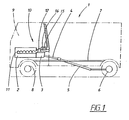
- Figure 1 shows a vehicle 1 which is equipped with an internal combustion engine 2 and a gearbox 3 coupled to this engine.
- the gearbox has an output driving shaft 4 which, via a propeller shaft 5, drives at least one pair of driving wheels 6.
- the vehicle 1 is constructed around a frame 7 which is supported by said driving wheels 6 and preferably a set of steerable wheels 8.
- the vehicle preferably comprises a cab 9.
- the internal combustion engine is equipped with an exhaust system 10 which comprises an exhaust pipe 11 connected to the outlet ports of the engine.
- a turbine 12 is preferably arranged in the exhaust system 10 and forms part of a turbo unit 13 and is thus mechanically coupled to a compressor 14 arranged on the intake side (not shown) of the engine.
- the engine is of the diesel type, which means that soot particles are formed during the combustion process.
- the exhaust system is therefore equipped with a particle filter 15.
- An oxidation catalyst 16 is arranged in thermal proximity to the particle filter. In thermal proximity means that the reaction which takes place in the oxidation catalyst is capable of heating the particle filter.
- the oxidation catalyst is usually mounted upstream of and in direct proximity to the particle filter, but it is also conceivable to integrate the particle filter and the oxidation catalyst on a common bearing structure where catalyst material is spread over the filtering body.
- the oxidation catalyst and the particle filter can preferably be designed as described in EP 341 832 or EP 835 684 .
- Soot particles are caught in the particle filter 13. Under favorable conditions, a continuous conversion of nitric oxide NO into nitrogen dioxide NO 2 takes place in the oxidation catalyst. Oxidation of the soot particles then takes place in a nitrogen dioxide environment, the soot particles being oxidized to form carbon dioxide in one, some or all of the processes NO 2 + C ⁇ NO + CO, NO 2 + C ⁇ 1 ⁇ 2N 2 + CO 2 or 2NO 2 + C ⁇ 2NO + CO 2 .
- the soot particles can also react directly with the excess oxygen O 2 present in diesel exhaust gases, but a prerequisite for this is that the temperature exceeds approximately 600°C.
- This reaction is several powers of ten faster than the reaction in which NO 2 reacts with the soot because the concentration of oxygen O 2 remaining in diesel exhaust gases is approximately three powers of ten greater than the concentrations of NO 2 are. If this temperature is used for regeneration of the soot filter, the whole regeneration can be limited to a few minutes.
- Fig. 2 shows in greater detail the internal combustion engine 2 which is arranged for regeneration of a particle filter according to the invention.
- the internal combustion engine preferably forms part of a driving unit for a truck or a bus.
- the engine is advantageously of the directly injected diesel engine type in which a turbo unit 13 with an exhaust-driven turbine 12 and a compressor 14 arranged on the turbine shaft is used for compression and supply of combustion air.
- Intake air is supplied to the supercharger from an air filter 17 for compression, after which the compressed air is cooled as it passes through an intercooler 18 before it is supplied to the intake manifold 19 of the engine.
- the exhaust gases of the engine are collected in a conventional way in an exhaust manifold 11 and are then conducted to the turbine 12 of the supercharger 13 for driving the compressor 14.
- the exhaust gases are then conducted onward via an exhaust pressure regulator 20 to a muffler unit 21 with a particle filter 15.
- the exhaust pressure regulator 20 can be of a kind known per se and comprises a piston valve with a pneumatically controlled piston 22 and a valve disk 23 mounted at the opposite end of a rod.
- a regulating air pressure acts against the piston 22 via a compressed-air line (not shown) which is connected to a compressed-air system contained in the vehicle, which is used for generating power for auxiliary units in the vehicle.
- Such input data is provided via, for example, a line 26 to the particle filter 15.
- the exhaust pressure regulator can be activated by, for example, detection of the particle quantity in the particle filter 15 having reached a certain level. Alternatively, activation can take place on detection of the pressure drop in the particle filter having reached a certain level. Another variant is to detect whether the engine has worked at low load for a certain time.
- the valve disk can therefore be set between fully open position and active position, where a given exhaust pressure is defined by the interaction of the valve with the gas flowing through.
- the exhaust pressure regulator 20 can be activated to different degrees depending on how hot the exhaust gases are.
- the exhaust gas temperature can be measured and the exhaust pressure regulator can be controlled until its desired temperature is obtained.
- the control unit of the engine can, with a known ambient temperature in combination with the current operating point, calculate the exhaust gas temperature and then control the exhaust pressure regulator until the desired exhaust gas temperature is obtained.
- Fig. 3 shows diagrammatically the volumetric flow of injected fuel quantity during normal operation and at low engine load during regeneration.
- the regulation of injected fuel quantity and the angle position of the crankshaft when injection takes place are controlled by the control unit 24 in a manner well-known to the expert.
- An example of a control unit for vehicles is given in SAE J1939/71, 1996.
- the graph shows the volumetric flow as a function of the crankshaft angle position, which is indicated with the bottom and top dead centers of the piston as reference points.
- the four strokes of the internal combustion engine are indicated along the x axis, the intake stroke between 0° and 180°, the compression stroke between 180° and 360°, the expansion stroke between 360° and 540°, and the exhaust stroke between 540° and 720°.
- Curve A shows the fuel quantity supplied for an operating case when the engine is working under normal load. Fuel is then supplied at the transition between the compression stroke and the expansion stroke with a duration of between 3 and 30 crank angle degrees.
- the curves B 1 - B 3 show the fuel quantity supplied under low engine load for regeneration of a particle filter arranged downstream of an oxidation catalyst in the exhaust duct.
- the fuel is preferably supplied during the expansion stroke or the exhaust stroke within a range covering 30° to 90° after top dead center between the compression stroke and the expansion stroke. A wider range of 0° to 360° after top dead center between the compression stroke and the expansion stroke is possible, that is to say during the expansion stroke and the exhaust stroke.
- fuel is supplied between 30° and 180° after top dead center between the compression stroke and the expansion stroke.
- fuel is supplied 270° after top dead center.
Landscapes
- Engineering & Computer Science (AREA)
- Chemical & Material Sciences (AREA)
- Combustion & Propulsion (AREA)
- Mechanical Engineering (AREA)
- General Engineering & Computer Science (AREA)
- Chemical Kinetics & Catalysis (AREA)
- Physics & Mathematics (AREA)
- Thermal Sciences (AREA)
- Processes For Solid Components From Exhaust (AREA)
- Filtering Of Dispersed Particles In Gases (AREA)
- Exhaust Gas After Treatment (AREA)
- Electrical Control Of Air Or Fuel Supplied To Internal-Combustion Engine (AREA)
- Control Of Throttle Valves Provided In The Intake System Or In The Exhaust System (AREA)
- Combined Controls Of Internal Combustion Engines (AREA)
- Physical Or Chemical Processes And Apparatus (AREA)
- Filtration Of Liquid (AREA)
Claims (10)
- Procédé pour régénérer un filtre à particules (15) agencé à proximité thermique d'une unité de catalyse (16) dans un conduit d'échappement (10) relié à un moteur à combustion interne (2), lequel filtre à particules est positionné en amont d'un régulateur de pression d'échappement ajustable (5) pour réguler un écoulement d'échappement à travers le conduit d'échappement, caractérisé par les étapes consistant à :établir, par l'intermédiaire d'une unité de commande (24), que le moteur à combustion interne est entraîné à une faible charge de moteur,activer le régulateur de pression d'échappement (20) avec une pression de régulation prédéterminée, etalimenter du carburant vers le conduit échappement (10) par l'intermédiaire d'une unité d'injection, ladite unité de catalyse (7) étant exposée audit carburant, qui est oxydé, et le filtre à particules (15) étant chauffé à une température telle que des particules de suie sont converties en dioxyde de carbone en réaction avec de l'oxygène contenu dans ledit écoulement d'échappement.
- Procédé de régénération selon la revendication 1, caractérisé en ce que ladite unité d'injection alimente du carburant vers une chambre de combustion agencée dans le moteur à combustion interne (2) à un tel stade du cycle de travail du moteur à combustion interne que du carburant est autorisé à passer à travers la chambre de combustion jusque dans le conduit d'échappement (10) dans un état non brûlé ou partiellement brûlé, ledit carburant non brûlé ou partiellement brûlé étant oxydé lors d'un contact avec l'unité de catalyse (16), et le filtre à particules (15) étant chauffé à une température telle que des particules de suie sont converties en monoxyde de carbone en réaction avec de l'oxygène contenu dans ledit écoulement d'échappement.
- Procédé de régénération selon la revendication 2, caractérisé en ce que ledit carburant est alimenté pendant la course de détente ou la course d'échappement du moteur à combustion interne.
- Procédé de régénération selon la revendication 1, caractérisé en ce que le carburant est alimenté directement vers le conduit d'échappement (10) via une unité d'injection attribuée au conduit d'échappement.
- Procédé de régénération selon l'une quelconque des revendications précédentes, caractérisé en ce que du carburant est alimenté dans des cas dans lesquels la température des gaz d'échappement au niveau du filtre à particules (15) sous une faible charge et avec le régulateur de pression d'échappement activé est d'au moins 250°C.
- Véhicule (1) comprenant un moteur à combustion interne (2) et un filtre à particules (15) à proximité thermique d'une unité de catalyse (16) dans un conduit d'échappement (10) relié au moteur à combustion interne, lequel filtre à particules est situé en aval d'un régulateur de pression d'échappement ajustable (20) pour réguler un écoulement d'échappement à travers le conduit d'échappement, caractérisé en ce qu'un système d'injection attribué audit véhicule est agencé de manière à, lorsqu'une régénération du filtre à particules (15) est nécessaire, alimenter du carburant vers le conduit d'échappement (10) avec l'activation simultanée du régulateur de pression d'échappement (20), l'unité de catalyse (16) étant exposée audit carburant, qui est oxydé, et le filtre à particules étant chauffé à une température telle que des particules de suie sont converties en dioxyde de carbone en réaction avec de l'oxygène contenu dans ledit écoulement d'échappement.
- Véhicule selon la revendication 6, caractérisé en ce que le système d'injection est agencé de manière à alimenter du carburant vers les chambres de combustion agencées dans le moteur à combustion interne (2) à un stade tel du cycle de travail du moteur à combustion interne que du carburant est autorisé à passer à travers la chambre de combustion jusque dans le conduit d'échappement (10) dans un état non brûlé ou partiellement brûlé.
- Véhicule selon la revendication 7, caractérisé en ce que ledit système d'injection est agencé de manière à alimenter du carburant pendant la course de détente ou la course d'échappement du moteur à combustion interne.
- Véhicule selon la revendication 6, caractérisé en ce que le véhicule comprend une unité d'injection attribuée au conduit échappement (10), laquelle unité d'injection est agencée de manière à fournir du carburant directement vers le conduit d'échappement.
- Véhicule selon l'une quelconque des revendications 6 à 9, caractérisé en ce que le régulateur de pression d'échappement (20) comporte un piston actionné pneumatiquement (22) qui est relié à un disque de soupape (23) qui, lorsqu'il est déplacé dans la direction d'un siège, forme un étranglement pour l'écoulement d'échappement du moteur.
Applications Claiming Priority (3)
| Application Number | Priority Date | Filing Date | Title |
|---|---|---|---|
| SE0203250A SE524181C2 (sv) | 2002-11-05 | 2002-11-05 | Metod för regenerering av ett partikelfilter samt fordon i vilket en sådan metod utnyttjas |
| SE0203250 | 2002-11-05 | ||
| PCT/SE2003/001621 WO2004042206A1 (fr) | 2002-11-05 | 2003-10-20 | Procede de nettoyage d'un filtre a particules et vehicule exploitant ce procede |
Publications (2)
| Publication Number | Publication Date |
|---|---|
| EP1561015A1 EP1561015A1 (fr) | 2005-08-10 |
| EP1561015B1 true EP1561015B1 (fr) | 2009-07-01 |
Family
ID=20289456
Family Applications (1)
| Application Number | Title | Priority Date | Filing Date |
|---|---|---|---|
| EP03754335A Expired - Lifetime EP1561015B1 (fr) | 2002-11-05 | 2003-10-20 | Procede de nettoyage d'un filtre a particules et vehicule exploitant ce procede |
Country Status (10)
| Country | Link |
|---|---|
| US (1) | US20070006576A1 (fr) |
| EP (1) | EP1561015B1 (fr) |
| JP (1) | JP2006505738A (fr) |
| CN (1) | CN100365253C (fr) |
| AT (1) | ATE435361T1 (fr) |
| AU (1) | AU2003273119A1 (fr) |
| BR (1) | BR0315827B1 (fr) |
| DE (1) | DE60328217D1 (fr) |
| SE (1) | SE524181C2 (fr) |
| WO (1) | WO2004042206A1 (fr) |
Families Citing this family (19)
| Publication number | Priority date | Publication date | Assignee | Title |
|---|---|---|---|---|
| DE102004052670A1 (de) * | 2004-10-29 | 2006-05-04 | Daimlerchrysler Ag | Verfahren zum Betrieb einer Brennkraftmaschine im Motorbremsbetrieb |
| EP1744042B1 (fr) * | 2005-07-11 | 2012-02-22 | Ford Global Technologies, LLC | Méthode de régénération d'un filtre à particule |
| DE102005054387A1 (de) * | 2005-11-15 | 2007-05-16 | Bosch Gmbh Robert | Regeneration eines Partikelfilters durch Nacheinspritzung in Intervallen |
| CN103527289A (zh) * | 2006-06-13 | 2014-01-22 | 沃尔沃拉斯特瓦格纳公司 | 选择性催化还原系统和减少发动机氮氧化物排放的方法 |
| US9103274B2 (en) | 2006-07-29 | 2015-08-11 | Cummins Emission Solution Inc. | Multi-stage turbocharger system |
| GB0615143D0 (en) | 2006-07-29 | 2006-09-06 | Cummins Turbo Tech Ltd | Multi-stage turbocharger system |
| DE102006062491A1 (de) * | 2006-12-28 | 2008-07-03 | Robert Bosch Gmbh | Vorrichtung zur Dosierung von Kraftstoff zum Abgassystem eines Verbrennungsmotors |
| ITMI20071123A1 (it) * | 2007-06-01 | 2008-12-02 | Bosch Gmbh Robert | Metodo di rigenerazione del filtro antiparticolato di un motore a combustione interna e motore a combustione interna atto ad implementare tale metodo |
| GB0717212D0 (en) | 2007-09-05 | 2007-10-17 | Cummins Turbo Tech Ltd | Multi-stage turbocharger system |
| JP4561879B2 (ja) | 2008-06-10 | 2010-10-13 | 株式会社デンソー | 排気センサ再生装置およびそれを用いた吸排気制御システム |
| JP5101436B2 (ja) * | 2008-08-26 | 2012-12-19 | ヤンマー株式会社 | ディーゼルエンジン |
| JP4900410B2 (ja) * | 2009-03-25 | 2012-03-21 | トヨタ自動車株式会社 | 車両の制御装置 |
| US8109092B2 (en) * | 2009-05-28 | 2012-02-07 | Ford Global Technologies, Llc | Methods and systems for engine control |
| GB2475534B (en) | 2009-11-21 | 2014-11-12 | Cummins Turbo Tech Ltd | Sequential two-stage turbocharger system |
| US9995207B2 (en) | 2009-11-21 | 2018-06-12 | Cummins Turbo Technologies Limited | Multi-stage turbocharger system |
| US10054037B2 (en) | 2009-11-21 | 2018-08-21 | Cummins Turbo Technologies Limited | Multi-stage turbocharger system with bypass flowpaths and flow control valve |
| CN109356711A (zh) * | 2018-12-12 | 2019-02-19 | 中国北方发动机研究所(天津) | 一种可变排气涡轮 |
| CN113614351B (zh) * | 2019-03-20 | 2023-12-01 | 沃尔沃遍达公司 | 用于控制内燃机的方法和控制系统 |
| CN112973289B (zh) * | 2019-12-12 | 2025-03-07 | 伊利诺斯工具制品有限公司 | 废气净化装置 |
Family Cites Families (18)
| Publication number | Priority date | Publication date | Assignee | Title |
|---|---|---|---|---|
| US4505106A (en) * | 1981-12-02 | 1985-03-19 | Robertshaw Controls Company | Exhaust system for an internal combustion engine, burn-off unit and methods therefor |
| US4835963A (en) * | 1986-08-28 | 1989-06-06 | Allied-Signal Inc. | Diesel engine particulate trap regeneration system |
| DE3832790C2 (de) * | 1988-09-27 | 1997-12-11 | Pattas Konstantin N | Verfahren und Einrichtung zum Regenerieren eines Rußfilters |
| DE3834850A1 (de) * | 1988-10-13 | 1990-04-19 | Kloeckner Humboldt Deutz Ag | Brennstoffzufuhr zu einem regenerationsbrenner eines dieselpartikelfilters |
| US5050376A (en) * | 1990-02-08 | 1991-09-24 | Allied-Signal Inc. | Control system for diesel particulate trap regeneration system |
| IT1266889B1 (it) * | 1994-07-22 | 1997-01-21 | Fiat Ricerche | Metodo di autoinnesco della rigenerazione in un filtro particolato per un motore diesel con sistema d'iniezione a collettore comune. |
| JPH08109839A (ja) * | 1994-10-11 | 1996-04-30 | Fuji Oozx Inc | 内燃機関の排気ガス制御装置 |
| SE509524C2 (sv) * | 1997-06-04 | 1999-02-08 | Volvo Lastvagnar Ab | Förbränningsmotor med AT-regulator |
| JP3514218B2 (ja) * | 2000-07-24 | 2004-03-31 | トヨタ自動車株式会社 | 内燃機関の排気浄化装置 |
| JP3646635B2 (ja) * | 2000-08-25 | 2005-05-11 | トヨタ自動車株式会社 | 内燃機関の排気浄化装置 |
| WO2002026379A1 (fr) * | 2000-09-29 | 2002-04-04 | Omg Ag & Co. Kg | Filtre catalytique de particules de suie et utilisation de celui-ci afin de traiter des gaz d'echappement pauvres |
| JP2002122015A (ja) * | 2000-10-13 | 2002-04-26 | Hino Motors Ltd | 排気浄化方法及び装置 |
| JP2002242732A (ja) * | 2001-02-20 | 2002-08-28 | Nissan Motor Co Ltd | 内燃機関の排気浄化装置 |
| JP3843746B2 (ja) * | 2001-03-15 | 2006-11-08 | いすゞ自動車株式会社 | 連続再生型ディーゼルパティキュレートフィルタシステムとその再生制御方法 |
| JP2002349241A (ja) * | 2001-05-24 | 2002-12-04 | Isuzu Motors Ltd | ディーゼルエンジンの排気浄化装置 |
| KR100504422B1 (ko) * | 2001-09-07 | 2005-07-29 | 미쓰비시 지도샤 고교(주) | 엔진의 배기 정화 장치 |
| JP3876705B2 (ja) * | 2001-12-13 | 2007-02-07 | いすゞ自動車株式会社 | ディーゼルエンジンの排気ガス浄化システム |
| JP4175281B2 (ja) * | 2004-03-31 | 2008-11-05 | いすゞ自動車株式会社 | 排気ガス浄化システムの制御方法及び排気ガス浄化システム |
-
2002
- 2002-11-05 SE SE0203250A patent/SE524181C2/sv not_active IP Right Cessation
-
2003
- 2003-10-20 EP EP03754335A patent/EP1561015B1/fr not_active Expired - Lifetime
- 2003-10-20 CN CNB2003801026066A patent/CN100365253C/zh not_active Expired - Fee Related
- 2003-10-20 BR BRPI0315827-6A patent/BR0315827B1/pt not_active IP Right Cessation
- 2003-10-20 DE DE60328217T patent/DE60328217D1/de not_active Expired - Lifetime
- 2003-10-20 AT AT03754335T patent/ATE435361T1/de not_active IP Right Cessation
- 2003-10-20 WO PCT/SE2003/001621 patent/WO2004042206A1/fr not_active Ceased
- 2003-10-20 AU AU2003273119A patent/AU2003273119A1/en not_active Abandoned
- 2003-10-20 JP JP2004549758A patent/JP2006505738A/ja active Pending
-
2005
- 2005-05-04 US US10/908,265 patent/US20070006576A1/en not_active Abandoned
Also Published As
| Publication number | Publication date |
|---|---|
| EP1561015A1 (fr) | 2005-08-10 |
| US20070006576A1 (en) | 2007-01-11 |
| DE60328217D1 (de) | 2009-08-13 |
| SE0203250L (sv) | 2004-05-06 |
| BR0315827A (pt) | 2005-09-13 |
| ATE435361T1 (de) | 2009-07-15 |
| BR0315827B1 (pt) | 2012-06-12 |
| AU2003273119A1 (en) | 2004-06-07 |
| CN1714229A (zh) | 2005-12-28 |
| SE0203250D0 (sv) | 2002-11-05 |
| SE524181C2 (sv) | 2004-07-06 |
| CN100365253C (zh) | 2008-01-30 |
| WO2004042206A1 (fr) | 2004-05-21 |
| JP2006505738A (ja) | 2006-02-16 |
Similar Documents
| Publication | Publication Date | Title |
|---|---|---|
| EP1561015B1 (fr) | Procede de nettoyage d'un filtre a particules et vehicule exploitant ce procede | |
| US6276139B1 (en) | Automotive engine with controlled exhaust temperature and oxygen concentration | |
| US6594990B2 (en) | Method for regenerating a diesel particulate filter | |
| CN100404807C (zh) | 颗粒过滤器的再生方法和使用这种方法的车辆 | |
| US6843055B2 (en) | Regeneration of diesel particulate filter for diesel engine | |
| US6978604B2 (en) | Soot burn-off control strategy for a catalyzed diesel particulate filter | |
| US6941755B2 (en) | Integrated bypass and variable geometry configuration for an exhaust gas turbocharger | |
| CN101493026B (zh) | 带有氧和温度控制的排气还原系统 | |
| US20100043428A1 (en) | Engine With Exhaust Temperature Control and Method of Controlling Engine Exhaust Gas Temperature and Engine Intake Temperature | |
| US20080104945A1 (en) | Diesel oxidation catalyst filter heating system | |
| JP5130933B2 (ja) | エンジンの過給装置 | |
| US20110120123A1 (en) | Low pressure turbine waste gate for diesel engine having two stage turbocharger | |
| US20090271094A1 (en) | Engine with charge air recirculation and method | |
| EP1929143B1 (fr) | Procede pour moteur a combustion interne avec recirculation des gaz d echappement | |
| EP1365125B1 (fr) | Procédé de réglage de la température des gaz d'échappement d'un moteur à combustion interne suralimenté | |
| JP5050903B2 (ja) | エンジンの過給装置 | |
| JP2004176636A (ja) | 内燃機関の排気浄化装置 | |
| JP2021092193A (ja) | 排ガス浄化システム及び排ガス浄化システムの再生方法 | |
| JP2006266219A (ja) | 後処理装置の昇温制御装置 | |
| JP2008038621A (ja) | 内燃機関の排気浄化装置、及び方法 |
Legal Events
| Date | Code | Title | Description |
|---|---|---|---|
| PUAI | Public reference made under article 153(3) epc to a published international application that has entered the european phase |
Free format text: ORIGINAL CODE: 0009012 |
|
| 17P | Request for examination filed |
Effective date: 20050606 |
|
| AK | Designated contracting states |
Kind code of ref document: A1 Designated state(s): AT BE BG CH CY CZ DE DK EE ES FI FR GB GR HU IE IT LI LU MC NL PT RO SE SI SK TR |
|
| AX | Request for extension of the european patent |
Extension state: AL LT LV MK |
|
| DAX | Request for extension of the european patent (deleted) | ||
| RIN1 | Information on inventor provided before grant (corrected) |
Inventor name: PERSSON, PER Inventor name: ALM, CHRISTER Inventor name: SVENSSON, BO |
|
| GRAP | Despatch of communication of intention to grant a patent |
Free format text: ORIGINAL CODE: EPIDOSNIGR1 |
|
| GRAS | Grant fee paid |
Free format text: ORIGINAL CODE: EPIDOSNIGR3 |
|
| GRAA | (expected) grant |
Free format text: ORIGINAL CODE: 0009210 |
|
| AK | Designated contracting states |
Kind code of ref document: B1 Designated state(s): AT BE BG CH CY CZ DE DK EE ES FI FR GB GR HU IE IT LI LU MC NL PT RO SE SI SK TR |
|
| REG | Reference to a national code |
Ref country code: GB Ref legal event code: FG4D |
|
| REG | Reference to a national code |
Ref country code: CH Ref legal event code: EP |
|
| REG | Reference to a national code |
Ref country code: IE Ref legal event code: FG4D |
|
| REF | Corresponds to: |
Ref document number: 60328217 Country of ref document: DE Date of ref document: 20090813 Kind code of ref document: P |
|
| PG25 | Lapsed in a contracting state [announced via postgrant information from national office to epo] |
Ref country code: SI Free format text: LAPSE BECAUSE OF FAILURE TO SUBMIT A TRANSLATION OF THE DESCRIPTION OR TO PAY THE FEE WITHIN THE PRESCRIBED TIME-LIMIT Effective date: 20090701 |
|
| NLV1 | Nl: lapsed or annulled due to failure to fulfill the requirements of art. 29p and 29m of the patents act | ||
| PG25 | Lapsed in a contracting state [announced via postgrant information from national office to epo] |
Ref country code: EE Free format text: LAPSE BECAUSE OF FAILURE TO SUBMIT A TRANSLATION OF THE DESCRIPTION OR TO PAY THE FEE WITHIN THE PRESCRIBED TIME-LIMIT Effective date: 20090701 Ref country code: ES Free format text: LAPSE BECAUSE OF FAILURE TO SUBMIT A TRANSLATION OF THE DESCRIPTION OR TO PAY THE FEE WITHIN THE PRESCRIBED TIME-LIMIT Effective date: 20091012 Ref country code: AT Free format text: LAPSE BECAUSE OF FAILURE TO SUBMIT A TRANSLATION OF THE DESCRIPTION OR TO PAY THE FEE WITHIN THE PRESCRIBED TIME-LIMIT Effective date: 20090701 Ref country code: FI Free format text: LAPSE BECAUSE OF FAILURE TO SUBMIT A TRANSLATION OF THE DESCRIPTION OR TO PAY THE FEE WITHIN THE PRESCRIBED TIME-LIMIT Effective date: 20090701 Ref country code: SE Free format text: LAPSE BECAUSE OF FAILURE TO SUBMIT A TRANSLATION OF THE DESCRIPTION OR TO PAY THE FEE WITHIN THE PRESCRIBED TIME-LIMIT Effective date: 20090701 |
|
| PG25 | Lapsed in a contracting state [announced via postgrant information from national office to epo] |
Ref country code: NL Free format text: LAPSE BECAUSE OF FAILURE TO SUBMIT A TRANSLATION OF THE DESCRIPTION OR TO PAY THE FEE WITHIN THE PRESCRIBED TIME-LIMIT Effective date: 20090701 |
|
| PG25 | Lapsed in a contracting state [announced via postgrant information from national office to epo] |
Ref country code: PT Free format text: LAPSE BECAUSE OF FAILURE TO SUBMIT A TRANSLATION OF THE DESCRIPTION OR TO PAY THE FEE WITHIN THE PRESCRIBED TIME-LIMIT Effective date: 20091102 Ref country code: BG Free format text: LAPSE BECAUSE OF FAILURE TO SUBMIT A TRANSLATION OF THE DESCRIPTION OR TO PAY THE FEE WITHIN THE PRESCRIBED TIME-LIMIT Effective date: 20091001 |
|
| PG25 | Lapsed in a contracting state [announced via postgrant information from national office to epo] |
Ref country code: CZ Free format text: LAPSE BECAUSE OF FAILURE TO SUBMIT A TRANSLATION OF THE DESCRIPTION OR TO PAY THE FEE WITHIN THE PRESCRIBED TIME-LIMIT Effective date: 20090701 Ref country code: RO Free format text: LAPSE BECAUSE OF FAILURE TO SUBMIT A TRANSLATION OF THE DESCRIPTION OR TO PAY THE FEE WITHIN THE PRESCRIBED TIME-LIMIT Effective date: 20090701 Ref country code: DK Free format text: LAPSE BECAUSE OF FAILURE TO SUBMIT A TRANSLATION OF THE DESCRIPTION OR TO PAY THE FEE WITHIN THE PRESCRIBED TIME-LIMIT Effective date: 20090701 |
|
| PLBE | No opposition filed within time limit |
Free format text: ORIGINAL CODE: 0009261 |
|
| STAA | Information on the status of an ep patent application or granted ep patent |
Free format text: STATUS: NO OPPOSITION FILED WITHIN TIME LIMIT |
|
| PG25 | Lapsed in a contracting state [announced via postgrant information from national office to epo] |
Ref country code: SK Free format text: LAPSE BECAUSE OF FAILURE TO SUBMIT A TRANSLATION OF THE DESCRIPTION OR TO PAY THE FEE WITHIN THE PRESCRIBED TIME-LIMIT Effective date: 20090701 Ref country code: BE Free format text: LAPSE BECAUSE OF FAILURE TO SUBMIT A TRANSLATION OF THE DESCRIPTION OR TO PAY THE FEE WITHIN THE PRESCRIBED TIME-LIMIT Effective date: 20090701 Ref country code: MC Free format text: LAPSE BECAUSE OF NON-PAYMENT OF DUE FEES Effective date: 20091031 |
|
| REG | Reference to a national code |
Ref country code: CH Ref legal event code: PL |
|
| 26N | No opposition filed |
Effective date: 20100406 |
|
| PG25 | Lapsed in a contracting state [announced via postgrant information from national office to epo] |
Ref country code: LI Free format text: LAPSE BECAUSE OF NON-PAYMENT OF DUE FEES Effective date: 20091031 Ref country code: IE Free format text: LAPSE BECAUSE OF NON-PAYMENT OF DUE FEES Effective date: 20091020 Ref country code: GR Free format text: LAPSE BECAUSE OF FAILURE TO SUBMIT A TRANSLATION OF THE DESCRIPTION OR TO PAY THE FEE WITHIN THE PRESCRIBED TIME-LIMIT Effective date: 20091002 Ref country code: CH Free format text: LAPSE BECAUSE OF NON-PAYMENT OF DUE FEES Effective date: 20091031 |
|
| PG25 | Lapsed in a contracting state [announced via postgrant information from national office to epo] |
Ref country code: LU Free format text: LAPSE BECAUSE OF NON-PAYMENT OF DUE FEES Effective date: 20091020 |
|
| PG25 | Lapsed in a contracting state [announced via postgrant information from national office to epo] |
Ref country code: HU Free format text: LAPSE BECAUSE OF FAILURE TO SUBMIT A TRANSLATION OF THE DESCRIPTION OR TO PAY THE FEE WITHIN THE PRESCRIBED TIME-LIMIT Effective date: 20100102 |
|
| PG25 | Lapsed in a contracting state [announced via postgrant information from national office to epo] |
Ref country code: TR Free format text: LAPSE BECAUSE OF FAILURE TO SUBMIT A TRANSLATION OF THE DESCRIPTION OR TO PAY THE FEE WITHIN THE PRESCRIBED TIME-LIMIT Effective date: 20090701 |
|
| PG25 | Lapsed in a contracting state [announced via postgrant information from national office to epo] |
Ref country code: CY Free format text: LAPSE BECAUSE OF FAILURE TO SUBMIT A TRANSLATION OF THE DESCRIPTION OR TO PAY THE FEE WITHIN THE PRESCRIBED TIME-LIMIT Effective date: 20090701 |
|
| REG | Reference to a national code |
Ref country code: FR Ref legal event code: PLFP Year of fee payment: 13 |
|
| REG | Reference to a national code |
Ref country code: FR Ref legal event code: PLFP Year of fee payment: 14 |
|
| REG | Reference to a national code |
Ref country code: FR Ref legal event code: PLFP Year of fee payment: 15 |
|
| REG | Reference to a national code |
Ref country code: FR Ref legal event code: PLFP Year of fee payment: 16 |
|
| PGFP | Annual fee paid to national office [announced via postgrant information from national office to epo] |
Ref country code: DE Payment date: 20191129 Year of fee payment: 17 |
|
| PGFP | Annual fee paid to national office [announced via postgrant information from national office to epo] |
Ref country code: FR Payment date: 20191025 Year of fee payment: 17 Ref country code: IT Payment date: 20191024 Year of fee payment: 17 |
|
| PGFP | Annual fee paid to national office [announced via postgrant information from national office to epo] |
Ref country code: GB Payment date: 20191029 Year of fee payment: 17 |
|
| REG | Reference to a national code |
Ref country code: DE Ref legal event code: R119 Ref document number: 60328217 Country of ref document: DE |
|
| GBPC | Gb: european patent ceased through non-payment of renewal fee |
Effective date: 20201020 |
|
| PG25 | Lapsed in a contracting state [announced via postgrant information from national office to epo] |
Ref country code: DE Free format text: LAPSE BECAUSE OF NON-PAYMENT OF DUE FEES Effective date: 20210501 Ref country code: FR Free format text: LAPSE BECAUSE OF NON-PAYMENT OF DUE FEES Effective date: 20201031 |
|
| PG25 | Lapsed in a contracting state [announced via postgrant information from national office to epo] |
Ref country code: GB Free format text: LAPSE BECAUSE OF NON-PAYMENT OF DUE FEES Effective date: 20201020 |
|
| PG25 | Lapsed in a contracting state [announced via postgrant information from national office to epo] |
Ref country code: IT Free format text: LAPSE BECAUSE OF NON-PAYMENT OF DUE FEES Effective date: 20201020 |