EP1563192B1 - Fluidkreislauf zur versorgung von primär- und sekundärverbrauchern mit festgelegter priorität - Google Patents
Fluidkreislauf zur versorgung von primär- und sekundärverbrauchern mit festgelegter priorität Download PDFInfo
- Publication number
- EP1563192B1 EP1563192B1 EP03772455A EP03772455A EP1563192B1 EP 1563192 B1 EP1563192 B1 EP 1563192B1 EP 03772455 A EP03772455 A EP 03772455A EP 03772455 A EP03772455 A EP 03772455A EP 1563192 B1 EP1563192 B1 EP 1563192B1
- Authority
- EP
- European Patent Office
- Prior art keywords
- user
- configuration
- fluid
- signal line
- pressure signal
- Prior art date
- Legal status (The legal status is an assumption and is not a legal conclusion. Google has not performed a legal analysis and makes no representation as to the accuracy of the status listed.)
- Expired - Lifetime
Links
Images

Classifications
-
- F—MECHANICAL ENGINEERING; LIGHTING; HEATING; WEAPONS; BLASTING
- F15—FLUID-PRESSURE ACTUATORS; HYDRAULICS OR PNEUMATICS IN GENERAL
- F15B—SYSTEMS ACTING BY MEANS OF FLUIDS IN GENERAL; FLUID-PRESSURE ACTUATORS, e.g. SERVOMOTORS; DETAILS OF FLUID-PRESSURE SYSTEMS, NOT OTHERWISE PROVIDED FOR
- F15B11/00—Servomotor systems without provision for follow-up action; Circuits therefor
- F15B11/16—Servomotor systems without provision for follow-up action; Circuits therefor with two or more servomotors
- F15B11/161—Servomotor systems without provision for follow-up action; Circuits therefor with two or more servomotors with sensing of servomotor demand or load
- F15B11/162—Servomotor systems without provision for follow-up action; Circuits therefor with two or more servomotors with sensing of servomotor demand or load for giving priority to particular servomotors or users
-
- F—MECHANICAL ENGINEERING; LIGHTING; HEATING; WEAPONS; BLASTING
- F15—FLUID-PRESSURE ACTUATORS; HYDRAULICS OR PNEUMATICS IN GENERAL
- F15B—SYSTEMS ACTING BY MEANS OF FLUIDS IN GENERAL; FLUID-PRESSURE ACTUATORS, e.g. SERVOMOTORS; DETAILS OF FLUID-PRESSURE SYSTEMS, NOT OTHERWISE PROVIDED FOR
- F15B2211/00—Circuits for servomotor systems
- F15B2211/20—Fluid pressure source, e.g. accumulator or variable axial piston pump
- F15B2211/205—Systems with pumps
- F15B2211/2053—Type of pump
- F15B2211/20546—Type of pump variable capacity
- F15B2211/20553—Type of pump variable capacity with pilot circuit, e.g. for controlling a swash plate
-
- F—MECHANICAL ENGINEERING; LIGHTING; HEATING; WEAPONS; BLASTING
- F15—FLUID-PRESSURE ACTUATORS; HYDRAULICS OR PNEUMATICS IN GENERAL
- F15B—SYSTEMS ACTING BY MEANS OF FLUIDS IN GENERAL; FLUID-PRESSURE ACTUATORS, e.g. SERVOMOTORS; DETAILS OF FLUID-PRESSURE SYSTEMS, NOT OTHERWISE PROVIDED FOR
- F15B2211/00—Circuits for servomotor systems
- F15B2211/40—Flow control
- F15B2211/405—Flow control characterised by the type of flow control means or valve
- F15B2211/40515—Flow control characterised by the type of flow control means or valve with variable throttles or orifices
-
- F—MECHANICAL ENGINEERING; LIGHTING; HEATING; WEAPONS; BLASTING
- F15—FLUID-PRESSURE ACTUATORS; HYDRAULICS OR PNEUMATICS IN GENERAL
- F15B—SYSTEMS ACTING BY MEANS OF FLUIDS IN GENERAL; FLUID-PRESSURE ACTUATORS, e.g. SERVOMOTORS; DETAILS OF FLUID-PRESSURE SYSTEMS, NOT OTHERWISE PROVIDED FOR
- F15B2211/00—Circuits for servomotor systems
- F15B2211/40—Flow control
- F15B2211/405—Flow control characterised by the type of flow control means or valve
- F15B2211/40523—Flow control characterised by the type of flow control means or valve with flow dividers
- F15B2211/4053—Flow control characterised by the type of flow control means or valve with flow dividers using valves
-
- F—MECHANICAL ENGINEERING; LIGHTING; HEATING; WEAPONS; BLASTING
- F15—FLUID-PRESSURE ACTUATORS; HYDRAULICS OR PNEUMATICS IN GENERAL
- F15B—SYSTEMS ACTING BY MEANS OF FLUIDS IN GENERAL; FLUID-PRESSURE ACTUATORS, e.g. SERVOMOTORS; DETAILS OF FLUID-PRESSURE SYSTEMS, NOT OTHERWISE PROVIDED FOR
- F15B2211/00—Circuits for servomotor systems
- F15B2211/40—Flow control
- F15B2211/455—Control of flow in the feed line, i.e. meter-in control
-
- F—MECHANICAL ENGINEERING; LIGHTING; HEATING; WEAPONS; BLASTING
- F15—FLUID-PRESSURE ACTUATORS; HYDRAULICS OR PNEUMATICS IN GENERAL
- F15B—SYSTEMS ACTING BY MEANS OF FLUIDS IN GENERAL; FLUID-PRESSURE ACTUATORS, e.g. SERVOMOTORS; DETAILS OF FLUID-PRESSURE SYSTEMS, NOT OTHERWISE PROVIDED FOR
- F15B2211/00—Circuits for servomotor systems
- F15B2211/60—Circuit components or control therefor
- F15B2211/605—Load sensing circuits
- F15B2211/6051—Load sensing circuits having valve means between output member and the load sensing circuit
- F15B2211/6054—Load sensing circuits having valve means between output member and the load sensing circuit using shuttle valves
-
- F—MECHANICAL ENGINEERING; LIGHTING; HEATING; WEAPONS; BLASTING
- F15—FLUID-PRESSURE ACTUATORS; HYDRAULICS OR PNEUMATICS IN GENERAL
- F15B—SYSTEMS ACTING BY MEANS OF FLUIDS IN GENERAL; FLUID-PRESSURE ACTUATORS, e.g. SERVOMOTORS; DETAILS OF FLUID-PRESSURE SYSTEMS, NOT OTHERWISE PROVIDED FOR
- F15B2211/00—Circuits for servomotor systems
- F15B2211/70—Output members, e.g. hydraulic motors or cylinders or control therefor
- F15B2211/71—Multiple output members, e.g. multiple hydraulic motors or cylinders
-
- F—MECHANICAL ENGINEERING; LIGHTING; HEATING; WEAPONS; BLASTING
- F15—FLUID-PRESSURE ACTUATORS; HYDRAULICS OR PNEUMATICS IN GENERAL
- F15B—SYSTEMS ACTING BY MEANS OF FLUIDS IN GENERAL; FLUID-PRESSURE ACTUATORS, e.g. SERVOMOTORS; DETAILS OF FLUID-PRESSURE SYSTEMS, NOT OTHERWISE PROVIDED FOR
- F15B2211/00—Circuits for servomotor systems
- F15B2211/70—Output members, e.g. hydraulic motors or cylinders or control therefor
- F15B2211/76—Control of force or torque of the output member
-
- F—MECHANICAL ENGINEERING; LIGHTING; HEATING; WEAPONS; BLASTING
- F15—FLUID-PRESSURE ACTUATORS; HYDRAULICS OR PNEUMATICS IN GENERAL
- F15B—SYSTEMS ACTING BY MEANS OF FLUIDS IN GENERAL; FLUID-PRESSURE ACTUATORS, e.g. SERVOMOTORS; DETAILS OF FLUID-PRESSURE SYSTEMS, NOT OTHERWISE PROVIDED FOR
- F15B2211/00—Circuits for servomotor systems
- F15B2211/70—Output members, e.g. hydraulic motors or cylinders or control therefor
- F15B2211/78—Control of multiple output members
- F15B2211/781—Control of multiple output members one or more output members having priority
Definitions
- This invention concerns a fluid-dynamic circuit for supplying primary and auxiliary users with preset priorities.
- the circuits that supply the different users are equipped with valves suitable for directing volumes of pressurised oil towards said users according to the priority with which said users have to be used.
- a main priority consists of supplying the power-assisted steering as it enables the operating machine to be driven in the desired directions.
- a secondary, albeit important, priority is considered to be supplying the braking system of the machine and any trailer attached thereto.
- auxiliary services i.e. the equipment with which the machine is equipped and which enable it to perform the different jobs for which it has been built.
- circuits that tend to consist of a single pump that is connected to a plurality of valves that are in turn serially connected together and interposed between the pump and the different users to provide them with supplying according to the preset priorities.
- the technical task of this invention is to eliminate the disadvantages of the prior art mentioned above by devising a fluid-dynamic circuit for supplying primary and auxiliary users with preset priorities that enables several users to be supplied with preset priorities, thereby limiting the load losses due to the presence of multiple valve organs.
- Another object of this invention is to perform the previous tasks with a fluid-dynamic circuit that has a simple structure and operates effectively, as well as having a relatively moderate coast, the number of valve organs to be used being limited.
- An hydraulic circuit capable to feed two users with a preset priority is also know from EP 1.245.834 .
- the priority is obtained by inserting a valve between the two users, in order to feed directly a first user and in parallel a second user.
- this patent teaches a circuit according to which a reservoir is foreseen instead of a third user and this reservoir is connected to the output of the first user: thus, a third user cannot be fed by a source directly.
- a further hydraulic feeding circuit is also known from US 2002/0166320 A1 , according to which a pump for feeding oil in pressure feeds directly a first motor for driving a fun shaft.
- the pump feeds also a second user, namely a second motor for driving the fun shaft, and a steering assembly is fed as a third user.
- This steering assembly is fed in series by a manifold that receives oil from the first and second motor.
- Another hydraulic circuit for feeding two users with a preset priority is known from FR 2.757.222 , according to which two distributors groups are fed with oil in pressure by a pump.
- Each group comprises a plurality of distribution stages each of one feeds a couple of working lines to be connected to working devices.
- US 50 20 324 A1 shows a fluid-dynamic circuit according to the preamble of claim 1.
- the technical task of this invention is to eliminate the disadvantages of the prior art mentioned above by devising fluid-dynamic circuit (1) for supplying primary and auxiliary users with preset priorities as claimed in claim 1.
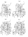
- 1 indicates overall a fluid-dynamic circuit for supplying primary and auxiliary uses with preset priorities.
- the circuit 1 comprises a pressurised fluid source, indicated overall by P, a first user with primary priority, indicated by PR1, a second user with secondary priority, indicated by PR2 and a third user with low priority, indicated by EF.
- a first pipe 2 connects said user PR1 with primary priority directly to said source P, whilst a second pipe 3 connects the source P to the user PR2 with secondary priority and a third pipe 4 connects the source P to the user EF with low priority.
- valve means 5 equipped with an internal distributor member 6 for the control of the connection between said first pipe 2 and second pipe 3 and third pipe 4.
- the distributor member 6 is movable according to at least three connection configurations: in a first configuration ( figure 1 ), indicated by 100 in the drawings, the users with secondary priority PR2 and the users with low priority EF are both shut; in a second configuration ( figure 2 ), indicated by 101, the users secondary priority PR2 and the users with low priority EF are open and shut respectively; in a third configuration ( figure 3 ), indicated by 102, the users with secondary priority PR2 and the users with low priority EF are both open.
- a first signal line 20 is provided for detecting the pressure of the fluid and the transmission of the relative signal; also between the users PR1 and PR2 a third and second signal line for measuring the pressure of said fluid are respectively provided, indicated respectively by 40 and 30; the second and third pressure signal lines 30 and 40 are better known by the technical term "load sensing".
- the first signal line 20 emerges on an end of the distributor means 6.
- the distributor member 6 is mobile between the three possible configurations 100, 101 and 102 through the action of the pressure differences between said first signal line 20 and the further signal line 20'.
- the selector organ 14 is of the conventional type and is used to transfer onto the further signal line 20' the greatest of the pressure signals detected on the second signal line 30 or on the third signal line 40.
- the distributor member 6 is also subjected to a continuous contrast action of elastic means 7 that exerts a preset force on the distributor member 6.
- the elastic means 7 shifts the distributor member 6 towards the first configuration 100.
- the distributor member 6 provides at least a first fourth configuration 103 interposed between the first configuration 100 and the second configuration 101 and a fifth configuration 104 interposed between the second configuration 101 and the third configuration 102.
- the second user PR2 is partially shut in the useful section of the passage of the pressurised fluid and the third user EF is shut.
- the second user PR2 is open and the third user EF is partially shut.
- the source P comprises a pumping unit that may be of the fixed-flow type, indicated by 8 or of the variable-flow type and indicated by 9.
- At least one protective valve means 10 of the use is interposable, said valve means 10 being equipped with an organ 11 with a presettable intervention threshold.
- the valve means 10 is also piloted by a shutter member 12 between at least two intervention positions: in a first position 200 the valve means 10 is open and the pressurised fluid flows freely towards the first user PR1 whereas in a second position 201 it is completely shut, thereby interrupting the flow of fluid directed towards said first user PR1.
- the organ 11 comprises at least one contrasting spring 13 that continuously acts in the opposite direction to the shift of the shutter member 12 to return it, or to keep it in the normal open configuration 200 of the valve means 10.
- valve means 14 is interposable that is suitable for limiting the maximum flow of the fluid directed towards said first user PR1.
- the operation of the fluid-dynamic circuit 1 for supplying primary users PR1, secondary users PR2 and auxiliary users EF with preset priorities is as follows: when the first user PR1 requires the entire maximum flow of pressurised fluid, the distributor member 6 of the valve means 5, subjected at one end to the diminishing pressure detected by the first signal line 20 and at the opposite end subjected to the pressure detected by the further signal line 20' and to the action of the elastic means 7, it is progressively arranged in the configuration 100 and sequentially closes the connections first with the third user EF and subsequently also with the second user PR2, as indicated in Figure 1 .
- Figure 2 illustrates an intermediate connection configuration 101, in other words with the distributor member 6 positioned in the configuration 101; in this configuration 101 the supply to the third user EF is shut whilst the supply to the first user PR1 and to the second user PR2 are open; this configuration occurs when the source P has sufficient flow to supply only the first user PR1 and the second user PR2.
- the fluid-dynamic circuit 1 is applied to an operating machine of the type used on construction sites or to a farm tractor the first user PR1 supplies the power-assisted steering, the second user PR2 supplies the braking system, the third user EF supplies the machine's services, in other words the work tools with which the said machine is equipped.
- the pressure of the further sensor line 20' acts on an end of the distributor member 6 and, at the opposite end, there is the action of the first signal line 20.
- the distributor member 6, when the operating machine is moving, is in the connection configuration indicated by 102, if the machine is equipped with a source P comprising a pump 9 with variable flow, or in the configuration 104 if the pump 8 is of the fixed-flow type.
- the signal line 20 detects a pressure drop signal; the elastic means 7 acts on the distributor member 6 of the valve means 5 and first pushes it and then maintains it in the connection configuration 100 wherein the second user PR2 and the third user EF are both shut.
- a fourth pressure-sensor line 50 is provided between the third user EF and the pump 9, also with the interposing of a second selector organ, indicated by 16, to which are added, in addition to the pressure signal detected by said line 50, also the greatest of the signals detected by the sensor organ 15: the second sensor organ 16 selects and sends to the pump 9 the greatest of said signals to pilot the overall flow of said pump.
- valve organ 10 can be positioned on the pipe 2, between the source P and the first user PR1 for protection, if requested by the latter in order that it does not reach an excessive non-required flow or pressure that might damage it.
- the disclosed invention achieves the proposed objects, in particular that it can supply by means of a sole valve means at least three uses with preset priorities and with minimal load loss.
Landscapes
- Engineering & Computer Science (AREA)
- Physics & Mathematics (AREA)
- Fluid Mechanics (AREA)
- Mechanical Engineering (AREA)
- General Engineering & Computer Science (AREA)
- Fluid-Pressure Circuits (AREA)
- External Artificial Organs (AREA)
- Nozzles (AREA)
- Vehicle Body Suspensions (AREA)
Claims (8)
- Fluiddynamischer Kreislauf (1) zum Versorgen von Primär-und Sekundärverbrauchern mit festgelegter Priorität, der eine Quelle eines unter Druck stehenden Fluids (P), mindestens einen ersten Verbraucher mit primärer Priorität (PR1), mindestens einen zweiten Verbraucher mit sekundärer Priorität (PR2), mindestens einen dritten Verbraucher mit niedriger Priorität (EF) aufweist, wobei der erste Verbraucher (PR1) über ein zugehöriges erstes Rohr (2) direkt mit der Quelle (P) verbunden ist, wobei der zweite Verbraucher (PR2) und der dritte Verbraucher (EF) über ein zweites (3) und ein drittes Rohr (4) durch Zwischenschaltung einer Ventileinrichtung (5), die mit einem Verteilerelement (6), das auf das zweite (3) und das dritte Rohr (4) wirkt und gemäß mindestens drei Verbindungskonfigurationen beweglich ist, ausgestattet ist, wobei in einer ersten Konfiguration (100) der zweite Verbraucher (PR2) und der dritte Verbraucher (EF) geschlossen sind, in einer zweiten Konfiguration (101) der zweite Verbraucher (PR2) geöffnet ist und der dritte Verbraucher (EF) geschlossen ist, in einer dritten Konfiguration (102) der zweite Verbraucher (PR2) geöffnet ist und der dritte Verbraucher (EF) geöffnet ist, mit der Quelle (P) verbindbar sind, dadurch gekennzeichnet, dass zwischen der Quelle (P) und der Ventileinrichtung (5) mindestens eine erste Signalleitung (20), die ein erstes Drucksignal des Fluids detektiert, bereitgestellt wird, dass zwischen dem zweiten Verbraucher (PR2) und der Ventileinrichtung (5) eine zweite Signalleitung (30), die ein zweites Drucksignal des Fluids detektiert, bereitgestellt wird, dass zwischen dem ersten Verbraucher (PR1) und der Ventileinrichtung (5) eine dritte Signalleitung (40), die ein drittes Drucksignal des Fluids detektiert, bereitgestellt wird.
- Fluiddynamischer Kreislauf (1) gemäß Anspruch 1, dadurch gekennzeichnet, dass die erste Drucksignalleitung (20), der zweiten Drucksignalleitung (30) und der dritten Drucksignalleitung (40) entgegenwirkend, mit dem Verteilerelement (6) der Ventileinrichtung (5) verbunden ist, wobei das Verteilerelement (6) beweglich zwischen mindestens drei der Verbindungskonfigurationen (100, 101, 102) durch Signalunterschiede, die durch die erste Drucksignalleitung (20) und durch die zweite (30) und die dritte Drucksignalleitung (40) detektierbar sind, betätigt wird.
- Fluiddynamischer Kreislauf (1) gemäß Anspruch 2, dadurch gekennzeichnet, dass die erste Drucksignalleitung (20) die Verschiebung des Verteilerelements (6) in Richtung auf das Öffnen von Verbindungskonfigurationen des zweiten Verbrauchers (PR2) und des dritten Verbrauchers (EF) aktiviert, wobei die zweite (30) und die dritte Drucksignalleitung (40) die Verschiebung des Verteilerelements (6) in Richtung auf das Schließen von Verbindungskonfigurationen des zweiten Verbrauchers (PR2) und des dritten Verbrauchers (EF) aktivieren.
- Fluiddynamischer Kreislauf (1) gemäß den Ansprüchen 2 und 3, dadurch gekennzeichnet, dass mindestens zwischen die zweite Drucksignalleitung (30) und die dritte (40) Drucksignalleitung ein Organ (15) geschaltet ist, welches das zweite und dritte Signal auswählt, wobei das größte von ihnen am Ausgang durch eine weitere Signalleitung (20') ausgewählt wird, die, in Bezug auf das erste Signal der ersten Signalleitung (20) entgegenwirkend, auf das Verteilerelement (6) wirkt.
- Fluiddynamischer Kreislauf (1) gemäß den Ansprüchen und 2, dadurch gekennzeichnet, dass das Verteilerelement (6) sich in der zweiten (101) und der dritten Verbindungskonfiguration (102) durch mindestens eine elastische Einrichtung (7) mit einer voreinstellbaren Reaktionskraft normalerweise abhebt, um das Verteilerelement (6) beim Fehlen der Signale der ersten Sensorleitung (20) und einer weiteren Sensorleitung (20') in die erste Konfiguration (100) zurückzuversetzen.
- Fluiddynamischer Kreislauf (1) gemäß Anspruch 1, dadurch gekennzeichnet, dass das Verteilerelement (6) in mindestens einer vierten Konfiguration (103) und einer fünften Konfiguration (104) positionierbar ist, wobei die vierte Konfiguration (103) sich zwischen der ersten Konfiguration (100) und der zweiten Konfiguration (101) befindet, die fünfte Konfiguration (104) sich zwischen der zweiten Konfiguration (101) und der dritten Konfiguration (102) befindet, wobei in der vierten Konfiguration (103) der zweite Verbrauchter (PR2) teilweise geschlossen ist und der dritte Verbraucher (EF) geschlossen ist, wobei in der fünften Konfiguration (104) der zweite Verbraucher (PR2) geöffnet ist und der dritte Verbraucher (DF) teilweise geschlossen ist.
- Fluiddynamischer Kreislauf (1) gemäß Anspruch 1, dadurch gekennzeichnet, dass die Quelle (P) eine Pumpeinheit (8) mit nicht veränderbarer Fördermenge aufweist.
- Fluiddynamischer Kreislauf (1) gemäß Anspruch 1, dadurch gekennzeichnet, dass die Quelle (P) eine Pumpeinheit (9) mit veränderbarer Fördermenge aufweiset.
Applications Claiming Priority (3)
| Application Number | Priority Date | Filing Date | Title |
|---|---|---|---|
| IT000332A ITMO20020332A1 (it) | 2002-11-15 | 2002-11-15 | Circuito fluidodinamico per la alimentazione di utenze primarie ed ausiliarie con priorita' predefinite. |
| ITMO20020332 | 2002-11-15 | ||
| PCT/IB2003/005191 WO2004046561A1 (en) | 2002-11-15 | 2003-11-17 | Fluid circuit for feeding primary and auxiliary users with preset priorities |
Publications (2)
| Publication Number | Publication Date |
|---|---|
| EP1563192A1 EP1563192A1 (de) | 2005-08-17 |
| EP1563192B1 true EP1563192B1 (de) | 2011-07-27 |
Family
ID=27677266
Family Applications (1)
| Application Number | Title | Priority Date | Filing Date |
|---|---|---|---|
| EP03772455A Expired - Lifetime EP1563192B1 (de) | 2002-11-15 | 2003-11-17 | Fluidkreislauf zur versorgung von primär- und sekundärverbrauchern mit festgelegter priorität |
Country Status (7)
| Country | Link |
|---|---|
| US (1) | US7204186B2 (de) |
| EP (1) | EP1563192B1 (de) |
| AT (1) | ATE518065T1 (de) |
| AU (1) | AU2003280064A1 (de) |
| DK (1) | DK1563192T3 (de) |
| IT (1) | ITMO20020332A1 (de) |
| WO (1) | WO2004046561A1 (de) |
Families Citing this family (8)
| Publication number | Priority date | Publication date | Assignee | Title |
|---|---|---|---|---|
| ITMO20050220A1 (it) * | 2005-08-31 | 2007-03-01 | Studio Tecnico 6M Srl | Dispositivo fluidodinamico |
| DE102005047310A1 (de) * | 2005-09-30 | 2007-04-05 | Bosch Rexroth Ag | Hydraulische Steuervorrichtung |
| DE102007045802A1 (de) * | 2007-08-16 | 2009-02-19 | Robert Bosch Gmbh | Hydraulische Steueranordnung |
| US8193586B2 (en) * | 2008-08-25 | 2012-06-05 | Taiwan Semiconductor Manufacturing Company, Ltd. | Sealing structure for high-K metal gate |
| DE102010023495B3 (de) * | 2010-06-11 | 2011-09-15 | Airbus Operations Gmbh | Prioritätsventilanordnung, Verfahren zum Betreiben einer Prioritätsventilanordnung und Fluidsystem |
| US8862337B2 (en) * | 2010-07-28 | 2014-10-14 | Illinois Tool Works Inc. | Hydraulic tool control that switches output |
| IT202300025035A1 (it) | 2023-11-24 | 2025-05-24 | Safim S R L | Circuito fluidodinamico per l’alimentazione di utenze primarie ed ausiliarie con priorità predefinite |
| EP4653709A1 (de) | 2024-05-21 | 2025-11-26 | SAFIM S.r.l. | Ventilanordnung |
Citations (1)
| Publication number | Priority date | Publication date | Assignee | Title |
|---|---|---|---|---|
| US5020324A (en) * | 1990-03-13 | 1991-06-04 | Deere & Company | Charge flow priority circuit |
Family Cites Families (7)
| Publication number | Priority date | Publication date | Assignee | Title |
|---|---|---|---|---|
| US3971216A (en) * | 1974-06-19 | 1976-07-27 | The Scott & Fetzer Company | Load responsive system with synthetic signal |
| US4556078A (en) * | 1984-06-15 | 1985-12-03 | Deere & Company | Priority valve |
| FR2757222B1 (fr) | 1996-12-17 | 2000-12-01 | Mannesmann Rexroth Sa | Dispositif de distribution hydraulique multiple |
| JPH11115780A (ja) * | 1997-10-15 | 1999-04-27 | Komatsu Ltd | 作業車両用ステアリングポンプの容量制御方法および装置 |
| US6460655B2 (en) * | 2001-01-18 | 2002-10-08 | Deere & Company | Vehicle hydraulic system |
| DE10115650A1 (de) | 2001-03-29 | 2002-10-02 | Bosch Gmbh Robert | Hydraulische Steuereinrichtung |
| US6629411B2 (en) | 2001-05-09 | 2003-10-07 | Valeo Electrical Systems, Inc. | Dual displacement motor control |
-
2002
- 2002-11-15 IT IT000332A patent/ITMO20020332A1/it unknown
-
2003
- 2003-11-17 DK DK03772455.6T patent/DK1563192T3/da active
- 2003-11-17 US US10/534,875 patent/US7204186B2/en not_active Expired - Lifetime
- 2003-11-17 AU AU2003280064A patent/AU2003280064A1/en not_active Abandoned
- 2003-11-17 WO PCT/IB2003/005191 patent/WO2004046561A1/en not_active Ceased
- 2003-11-17 EP EP03772455A patent/EP1563192B1/de not_active Expired - Lifetime
- 2003-11-17 AT AT03772455T patent/ATE518065T1/de not_active IP Right Cessation
Patent Citations (1)
| Publication number | Priority date | Publication date | Assignee | Title |
|---|---|---|---|---|
| US5020324A (en) * | 1990-03-13 | 1991-06-04 | Deere & Company | Charge flow priority circuit |
Also Published As
| Publication number | Publication date |
|---|---|
| EP1563192A1 (de) | 2005-08-17 |
| AU2003280064A1 (en) | 2004-06-15 |
| US7204186B2 (en) | 2007-04-17 |
| ATE518065T1 (de) | 2011-08-15 |
| ITMO20020332A1 (it) | 2004-05-16 |
| WO2004046561A1 (en) | 2004-06-03 |
| US20050284143A1 (en) | 2005-12-29 |
| ITMO20020332A0 (it) | 2002-11-15 |
| DK1563192T3 (da) | 2011-11-14 |
Similar Documents
| Publication | Publication Date | Title |
|---|---|---|
| AU2009217448B2 (en) | Active implement down force system providing reduced heat generation | |
| US6681568B2 (en) | Fluid system for two hydraulic circuits having a common source of pressurized fluid | |
| US6408977B1 (en) | Hydraulic steering system for a vehicle, especially for a mobile working machine | |
| US7849956B2 (en) | On-demand electro-hydraulic steering system | |
| US6848255B2 (en) | Hydraulic fan drive system | |
| EP1826415A2 (de) | Hydrauliksystem für Nutzfahrzeuge, insbesondere für landwirtschaftliche Traktoren | |
| US5419129A (en) | Hydraulic system for open or closed-centered systems | |
| EP1843047B1 (de) | Hydraulische Zuführungssysteme | |
| EP1563192B1 (de) | Fluidkreislauf zur versorgung von primär- und sekundärverbrauchern mit festgelegter priorität | |
| US4005636A (en) | Hydraulic system for a working machine | |
| GB2081394A (en) | Hydraulic systems | |
| US4559965A (en) | Multiple compensating unloading valve circuit | |
| US4719753A (en) | Slide valve for load sensing control in a hydraulic system | |
| US20200095987A1 (en) | Control apparatus for supplying at least one hydraulic consumer with fluid | |
| US6318234B1 (en) | Line vent arrangement for electro-hydraulic circuit | |
| EP0836678B1 (de) | Hydraulisches sicherheitsbremsventil | |
| US5609221A (en) | Steering control system | |
| WO2008114109A1 (en) | Hydraulic apparatus | |
| EP0020105B1 (de) | Hydraulisches Bremssystem | |
| US5829251A (en) | Hydraulic control circuit for working components, in particular in earth-moving machines | |
| US4321855A (en) | Drive-assisting system comprising at least a fluid engine | |
| EP1008785A3 (de) | Automatische Schaltung für einen hydrostatischen Zweigangmotor eines Kleinschleppers | |
| US20070048146A1 (en) | Dynamic fluid device | |
| CA1164314A (en) | Hydraulic circuit selector with flow control | |
| US11053958B2 (en) | Regeneration valve for a hydraulic circuit |
Legal Events
| Date | Code | Title | Description |
|---|---|---|---|
| PUAI | Public reference made under article 153(3) epc to a published international application that has entered the european phase |
Free format text: ORIGINAL CODE: 0009012 |
|
| 17P | Request for examination filed |
Effective date: 20050608 |
|
| AK | Designated contracting states |
Kind code of ref document: A1 Designated state(s): AT BE BG CH CY CZ DE DK EE ES FI FR GB GR HU IE IT LI LU MC NL PT RO SE SI SK TR |
|
| AX | Request for extension of the european patent |
Extension state: AL LT LV MK |
|
| DAX | Request for extension of the european patent (deleted) | ||
| 17Q | First examination report despatched |
Effective date: 20060727 |
|
| GRAP | Despatch of communication of intention to grant a patent |
Free format text: ORIGINAL CODE: EPIDOSNIGR1 |
|
| GRAS | Grant fee paid |
Free format text: ORIGINAL CODE: EPIDOSNIGR3 |
|
| GRAA | (expected) grant |
Free format text: ORIGINAL CODE: 0009210 |
|
| RAP1 | Party data changed (applicant data changed or rights of an application transferred) |
Owner name: STUDIO TECNICO 6 M S.R.L. |
|
| REG | Reference to a national code |
Ref country code: DE Ref legal event code: R081 Ref document number: 60337844 Country of ref document: DE Owner name: SAFIM S.P.A., IT Free format text: FORMER OWNER: STUDIO TECNICO 6 M S.R.L., MODENA, IT |
|
| AK | Designated contracting states |
Kind code of ref document: B1 Designated state(s): AT BE BG CH CY CZ DE DK EE ES FI FR GB GR HU IE IT LI LU MC NL PT RO SE SI SK TR |
|
| REG | Reference to a national code |
Ref country code: GB Ref legal event code: FG4D |
|
| REG | Reference to a national code |
Ref country code: CH Ref legal event code: EP |
|
| REG | Reference to a national code |
Ref country code: DE Ref legal event code: R096 Ref document number: 60337844 Country of ref document: DE Effective date: 20110915 |
|
| REG | Reference to a national code |
Ref country code: DK Ref legal event code: T3 |
|
| REG | Reference to a national code |
Ref country code: NL Ref legal event code: VDEP Effective date: 20110727 |
|
| REG | Reference to a national code |
Ref country code: AT Ref legal event code: MK05 Ref document number: 518065 Country of ref document: AT Kind code of ref document: T Effective date: 20110727 |
|
| PG25 | Lapsed in a contracting state [announced via postgrant information from national office to epo] |
Ref country code: PT Free format text: LAPSE BECAUSE OF FAILURE TO SUBMIT A TRANSLATION OF THE DESCRIPTION OR TO PAY THE FEE WITHIN THE PRESCRIBED TIME-LIMIT Effective date: 20111128 Ref country code: BE Free format text: LAPSE BECAUSE OF FAILURE TO SUBMIT A TRANSLATION OF THE DESCRIPTION OR TO PAY THE FEE WITHIN THE PRESCRIBED TIME-LIMIT Effective date: 20110727 Ref country code: NL Free format text: LAPSE BECAUSE OF FAILURE TO SUBMIT A TRANSLATION OF THE DESCRIPTION OR TO PAY THE FEE WITHIN THE PRESCRIBED TIME-LIMIT Effective date: 20110727 Ref country code: SE Free format text: LAPSE BECAUSE OF FAILURE TO SUBMIT A TRANSLATION OF THE DESCRIPTION OR TO PAY THE FEE WITHIN THE PRESCRIBED TIME-LIMIT Effective date: 20110727 Ref country code: FI Free format text: LAPSE BECAUSE OF FAILURE TO SUBMIT A TRANSLATION OF THE DESCRIPTION OR TO PAY THE FEE WITHIN THE PRESCRIBED TIME-LIMIT Effective date: 20110727 |
|
| PG25 | Lapsed in a contracting state [announced via postgrant information from national office to epo] |
Ref country code: GR Free format text: LAPSE BECAUSE OF FAILURE TO SUBMIT A TRANSLATION OF THE DESCRIPTION OR TO PAY THE FEE WITHIN THE PRESCRIBED TIME-LIMIT Effective date: 20111028 Ref country code: AT Free format text: LAPSE BECAUSE OF FAILURE TO SUBMIT A TRANSLATION OF THE DESCRIPTION OR TO PAY THE FEE WITHIN THE PRESCRIBED TIME-LIMIT Effective date: 20110727 Ref country code: SI Free format text: LAPSE BECAUSE OF FAILURE TO SUBMIT A TRANSLATION OF THE DESCRIPTION OR TO PAY THE FEE WITHIN THE PRESCRIBED TIME-LIMIT Effective date: 20110727 Ref country code: CY Free format text: LAPSE BECAUSE OF FAILURE TO SUBMIT A TRANSLATION OF THE DESCRIPTION OR TO PAY THE FEE WITHIN THE PRESCRIBED TIME-LIMIT Effective date: 20110727 |
|
| PG25 | Lapsed in a contracting state [announced via postgrant information from national office to epo] |
Ref country code: SK Free format text: LAPSE BECAUSE OF FAILURE TO SUBMIT A TRANSLATION OF THE DESCRIPTION OR TO PAY THE FEE WITHIN THE PRESCRIBED TIME-LIMIT Effective date: 20110727 Ref country code: CZ Free format text: LAPSE BECAUSE OF FAILURE TO SUBMIT A TRANSLATION OF THE DESCRIPTION OR TO PAY THE FEE WITHIN THE PRESCRIBED TIME-LIMIT Effective date: 20110727 |
|
| PG25 | Lapsed in a contracting state [announced via postgrant information from national office to epo] |
Ref country code: RO Free format text: LAPSE BECAUSE OF FAILURE TO SUBMIT A TRANSLATION OF THE DESCRIPTION OR TO PAY THE FEE WITHIN THE PRESCRIBED TIME-LIMIT Effective date: 20110727 Ref country code: EE Free format text: LAPSE BECAUSE OF FAILURE TO SUBMIT A TRANSLATION OF THE DESCRIPTION OR TO PAY THE FEE WITHIN THE PRESCRIBED TIME-LIMIT Effective date: 20110727 |
|
| PLBE | No opposition filed within time limit |
Free format text: ORIGINAL CODE: 0009261 |
|
| STAA | Information on the status of an ep patent application or granted ep patent |
Free format text: STATUS: NO OPPOSITION FILED WITHIN TIME LIMIT |
|
| PG25 | Lapsed in a contracting state [announced via postgrant information from national office to epo] |
Ref country code: MC Free format text: LAPSE BECAUSE OF NON-PAYMENT OF DUE FEES Effective date: 20111130 |
|
| REG | Reference to a national code |
Ref country code: CH Ref legal event code: PL |
|
| 26N | No opposition filed |
Effective date: 20120502 |
|
| PG25 | Lapsed in a contracting state [announced via postgrant information from national office to epo] |
Ref country code: CH Free format text: LAPSE BECAUSE OF NON-PAYMENT OF DUE FEES Effective date: 20111130 Ref country code: LI Free format text: LAPSE BECAUSE OF NON-PAYMENT OF DUE FEES Effective date: 20111130 |
|
| REG | Reference to a national code |
Ref country code: DE Ref legal event code: R097 Ref document number: 60337844 Country of ref document: DE Effective date: 20120502 |
|
| REG | Reference to a national code |
Ref country code: IE Ref legal event code: MM4A |
|
| PG25 | Lapsed in a contracting state [announced via postgrant information from national office to epo] |
Ref country code: IE Free format text: LAPSE BECAUSE OF NON-PAYMENT OF DUE FEES Effective date: 20111117 |
|
| PG25 | Lapsed in a contracting state [announced via postgrant information from national office to epo] |
Ref country code: ES Free format text: LAPSE BECAUSE OF FAILURE TO SUBMIT A TRANSLATION OF THE DESCRIPTION OR TO PAY THE FEE WITHIN THE PRESCRIBED TIME-LIMIT Effective date: 20111107 |
|
| PG25 | Lapsed in a contracting state [announced via postgrant information from national office to epo] |
Ref country code: LU Free format text: LAPSE BECAUSE OF NON-PAYMENT OF DUE FEES Effective date: 20111117 |
|
| PG25 | Lapsed in a contracting state [announced via postgrant information from national office to epo] |
Ref country code: TR Free format text: LAPSE BECAUSE OF FAILURE TO SUBMIT A TRANSLATION OF THE DESCRIPTION OR TO PAY THE FEE WITHIN THE PRESCRIBED TIME-LIMIT Effective date: 20110727 |
|
| PG25 | Lapsed in a contracting state [announced via postgrant information from national office to epo] |
Ref country code: HU Free format text: LAPSE BECAUSE OF FAILURE TO SUBMIT A TRANSLATION OF THE DESCRIPTION OR TO PAY THE FEE WITHIN THE PRESCRIBED TIME-LIMIT Effective date: 20110727 |
|
| REG | Reference to a national code |
Ref country code: FR Ref legal event code: PLFP Year of fee payment: 13 |
|
| REG | Reference to a national code |
Ref country code: FR Ref legal event code: PLFP Year of fee payment: 14 |
|
| REG | Reference to a national code |
Ref country code: FR Ref legal event code: PLFP Year of fee payment: 15 |
|
| REG | Reference to a national code |
Ref country code: GB Ref legal event code: 732E Free format text: REGISTERED BETWEEN 20180315 AND 20180326 |
|
| REG | Reference to a national code |
Ref country code: DE Ref legal event code: R082 Ref document number: 60337844 Country of ref document: DE Representative=s name: MOSER GOETZE & PARTNER PATENTANWAELTE MBB, DE Ref country code: DE Ref legal event code: R081 Ref document number: 60337844 Country of ref document: DE Owner name: SAFIM S.P.A., IT Free format text: FORMER OWNER: STUDIO TECNICO 6 M S.R.L., MODENA, IT |
|
| REG | Reference to a national code |
Ref country code: FR Ref legal event code: GC Effective date: 20180725 Ref country code: FR Ref legal event code: TP Owner name: SAFIM S.P.A., IT Effective date: 20180724 |
|
| PGFP | Annual fee paid to national office [announced via postgrant information from national office to epo] |
Ref country code: IT Payment date: 20221121 Year of fee payment: 20 Ref country code: GB Payment date: 20221128 Year of fee payment: 20 Ref country code: FR Payment date: 20221123 Year of fee payment: 20 Ref country code: DK Payment date: 20221125 Year of fee payment: 20 Ref country code: DE Payment date: 20221125 Year of fee payment: 20 Ref country code: BG Payment date: 20221109 Year of fee payment: 20 |
|
| P01 | Opt-out of the competence of the unified patent court (upc) registered |
Effective date: 20230527 |
|
| REG | Reference to a national code |
Ref country code: DE Ref legal event code: R071 Ref document number: 60337844 Country of ref document: DE |
|
| REG | Reference to a national code |
Ref country code: DK Ref legal event code: EUP Expiry date: 20231117 |
|
| REG | Reference to a national code |
Ref country code: GB Ref legal event code: PE20 Expiry date: 20231116 |
|
| PG25 | Lapsed in a contracting state [announced via postgrant information from national office to epo] |
Ref country code: GB Free format text: LAPSE BECAUSE OF EXPIRATION OF PROTECTION Effective date: 20231116 |
|
| PG25 | Lapsed in a contracting state [announced via postgrant information from national office to epo] |
Ref country code: GB Free format text: LAPSE BECAUSE OF EXPIRATION OF PROTECTION Effective date: 20231116 |