EP1564336B1 - Elément de construction thermo-isolant - Google Patents
Elément de construction thermo-isolant Download PDFInfo
- Publication number
- EP1564336B1 EP1564336B1 EP04002982A EP04002982A EP1564336B1 EP 1564336 B1 EP1564336 B1 EP 1564336B1 EP 04002982 A EP04002982 A EP 04002982A EP 04002982 A EP04002982 A EP 04002982A EP 1564336 B1 EP1564336 B1 EP 1564336B1
- Authority
- EP
- European Patent Office
- Prior art keywords
- construction element
- element according
- bearing
- insulating body
- encasing
- Prior art date
- Legal status (The legal status is an assumption and is not a legal conclusion. Google has not performed a legal analysis and makes no representation as to the accuracy of the status listed.)
- Expired - Lifetime
Links
- 238000010276 construction Methods 0.000 title claims abstract 20
- 239000000463 material Substances 0.000 claims abstract description 18
- 239000004033 plastic Substances 0.000 claims abstract description 8
- 229920003023 plastic Polymers 0.000 claims abstract description 8
- 229910001220 stainless steel Inorganic materials 0.000 claims abstract description 7
- 239000010935 stainless steel Substances 0.000 claims abstract description 7
- 230000003014 reinforcing effect Effects 0.000 claims abstract description 6
- 229910052500 inorganic mineral Inorganic materials 0.000 claims abstract description 3
- 239000011707 mineral Substances 0.000 claims abstract description 3
- 230000007704 transition Effects 0.000 claims description 4
- 239000002131 composite material Substances 0.000 claims description 2
- 239000011518 fibre cement Substances 0.000 claims 1
- 238000005266 casting Methods 0.000 abstract 1
- 238000010008 shearing Methods 0.000 abstract 1
- 230000002787 reinforcement Effects 0.000 description 6
- 239000004568 cement Substances 0.000 description 2
- 230000002349 favourable effect Effects 0.000 description 2
- 239000000835 fiber Substances 0.000 description 2
- 239000012212 insulator Substances 0.000 description 2
- 238000004519 manufacturing process Methods 0.000 description 2
- 230000002093 peripheral effect Effects 0.000 description 2
- 229910000831 Steel Inorganic materials 0.000 description 1
- 238000009415 formwork Methods 0.000 description 1
- 238000003780 insertion Methods 0.000 description 1
- 230000037431 insertion Effects 0.000 description 1
- 238000009434 installation Methods 0.000 description 1
- 238000009413 insulation Methods 0.000 description 1
- 238000000034 method Methods 0.000 description 1
- 239000010959 steel Substances 0.000 description 1
Images


Classifications
-
- E—FIXED CONSTRUCTIONS
- E04—BUILDING
- E04B—GENERAL BUILDING CONSTRUCTIONS; WALLS, e.g. PARTITIONS; ROOFS; FLOORS; CEILINGS; INSULATION OR OTHER PROTECTION OF BUILDINGS
- E04B1/00—Constructions in general; Structures which are not restricted either to walls, e.g. partitions, or floors or ceilings or roofs
- E04B1/003—Balconies; Decks
- E04B1/0038—Anchoring devices specially adapted therefor with means for preventing cold bridging
Definitions
- a thermally insulating component is described, which is intended for use in joints between load-bearing structural parts such as between a building ceiling and a balcony floor plate.
- This insulating component comprises an insulating body and reinforcing members, wherein the component is dimensioned for receiving tensile, compressive and shear forces.
- the insulating body based on the longitudinal direction, at intervals stainless steel bearings for receiving pressure and shear forces embedded, the stainless steel bearings having an upper portion and a lower portion. These regions have a greater extension in the transverse direction of the insulating body than an intermediate region lying therebetween.
- the stainless steel bearings are exposed on the longitudinal sides of the insulating so that between the upper region and lower region, a gap for receiving material of the building parts is formed.
- the inventive arrangement is given an extremely favorable temperature mobility between the building parts. Despite the simple design of the pressure and thrust bearings can shear force bars, which extend obliquely through the insulator omitted.
- the bearing for receiving pressure and shear forces consists of an enveloping body with a filling.
- the enveloping body is tubular, in particular, a shape is to be considered as a flat tube into consideration.
- the enveloping body can also consist of at least one shell. If only one shell is provided, then it is correspondingly deeply formed in order to create the necessary volume for the filling of the castable or sprayable curable material.
- the enveloping body consists of two shells, which are each provided separately with a filling and are joined with their respective open sides against each other.
- the shells have a shape which is formed in each case mirror images of the open sides. This results in the assembly of the respective halves not only a generally closed form of the envelope, but it also installation errors are avoided in the insulating body, since the upper edge and lower edge of the bearing are formed in the same way.
- Suitable materials for the enveloping body are both plastics and stainless steel into consideration.
- the enveloping body is preferably produced as a deep-drawn part and has a sheet thickness of about 0.5 mm.
- the enveloping body is expediently filled with a fiber cement, but alternatively, the enveloping body may also be filled with a plastic.
- a projection in the direction of the load-absorbing structural parts is formed on each end face of the bearing, that is, the projection extends transversely to Longitudinal direction of the insulating body.
- These projections are, based on the transverse to the longitudinal direction of the insulating body extending surface of the bearing, formed diametrically on this surface, so that there is a projection on the upper edge of the bearing and the other projection on the lower edge of the bearing. It is advantageous that the dimension of the bearing over its length minus the projections at least approximately corresponds to the width of the insulating body, so that the projections protrude beyond the width of the insulating body.
- the bearing may also have a length such that the narrow sides formed on the bearing protrude from the contour of the insulating body.
- the projections are formed from an extension of the upper edge and lower edge of the bearing and of an arcuate transition to the end face and have at the outer end a rounding. Particularly favorable properties with respect to the temperature mobility are achieved when the flat tube has rounded narrow sides.
- the bearing is provided with at least one opening extending in the longitudinal direction of the insulating opening, which serves to receive a positioning strip, a rod or the like.
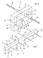
- pressure and thrust bearings are arranged at regular intervals and preferably in each case below the tensile reinforcement, which, as is clear from Fig. 1, slightly protrude at the longitudinal sides of the lower layer 4, and thus, based on the longitudinal extent of the insulating body 2 when pouring the building parts into the concrete later.
- the shape and structure of the pressure and thrust bearing 6 will be explained later in more detail.
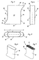
- FIGS. 3, 4 and 5 show different views of an enveloping body 10, which forms the shape for the thrust and thrust bearing 6 in FIG. 2.
- the enveloping body 10 is shown in the embodiment of FIGS. 3, 4 and 5 as a flat tube 12, the two parallel flat sides 13 and two narrow sides 14 includes, and whose height is limited by an upper edge 15 and a lower edge 16.
- projections 17 are formed, one at the upper edge 15 and one at the lower edge 16, these projections 17 being diametrically opposed.
- the projections 17 are thus formed by an extension of the upper edge 15 and lower edge 16 and in each case an arcuate transition 18 to the narrow side 14, wherein the outer end 19 of the projections 17 is rounded.
- the flat tube 12 has an extension of a length L1 relative to the narrow sides 14.
- This dimension L1 is preferably greater than the width B of the lower layer 4 shown in FIG. 2, so that it can already reach an engagement in the adjacent concrete elements. Based on the projections 17, the overall length L2 is even greater.
- FIGS. 6 and 7 the enveloping body 10 is shown in each case in perspective, which is formed from the flat tube 12. While the enveloping body 10 shown in Fig. 6 is still unfilled, Fig. 7 shows the filled with a filling 11 envelope body 10, wherein the material of the filling 11 is a pourable and / or sprayable curable material.
- This material can be essentially a dimensionally stable plastic of high strength, but there are also materials on a mineral basis into consideration such as fiber cement.
- One with Such a filling 11 provided enveloping body thus forms a bearing 6 for receiving pressure and shear forces.
- FIG. 8 shows an enveloping body 10, which is formed as a shell 22 of a bottom 23 and a peripheral side wall 24.
- FIG. 9, which shows a side view of this envelope body 10 formed by a shell 22, illustrates that the shell is open at the side 25 opposite the bottom 23. This open side 25 allows the filling of the shell 22 with a filling, as already described for Fig. 7. From Fig. 8 it is clear that the peripheral wall 24 is closed and also forms the contour with upper edge 15 and lower edge 16 and the projections 17 and arcuate transitions 18, as are the outer ends 19 are rounded.
- the shell 22 is preferably made as a deep-drawn part.
- FIG. 10 An alternative embodiment of a shell 21 is shown in Fig. 10, wherein the contour corresponds in plan view to that shown in Fig. 8. According to FIG. 10, only the shell 21 is of lesser depth, whereby the side walls 20 provided there are also rounded.
- a shell 21 For an enveloping body 10, preferably two such shells 21 are assembled into one unit, as shown in FIG. 11.
- two mirror-like shells 21 are each provided with the filling 11 and then joined together with the edges along its open side 25. This results in a pressure and thrust bearing 6, which also has a corresponding rounding in the region of the narrow sides 14 of the contour.
- FIG. 12 is a shell 26, which has the shape of a parallelogram in plan view.
- the bottom 27 is surrounded by a circumferential side wall 28, which is also closed, wherein the dimension L1 between two orthogonal lines S1, S2, which extend through the upper left and right lower corner, is formed, so that each laterally over this perpendicular Lines S1 and S2 protruding outlines of the parallelogram, the projections 17 form.
- a pressure and thrust bearing 6 which is suitable for use in an insulating body according to FIGS. 1 and 2.
Landscapes
- Engineering & Computer Science (AREA)
- Architecture (AREA)
- Physics & Mathematics (AREA)
- Electromagnetism (AREA)
- Civil Engineering (AREA)
- Structural Engineering (AREA)
- Building Environments (AREA)
- Cooling Or The Like Of Semiconductors Or Solid State Devices (AREA)
- Polymers With Sulfur, Phosphorus Or Metals In The Main Chain (AREA)
- Insulated Conductors (AREA)
- Sliding-Contact Bearings (AREA)
Claims (17)
- Elément de construction (1) thermo-isolant pour une utilisation dans des joints de séparation entre des parties d'édifice recevant des charges, par exemple entre un plafond de bâtiment et une plaque de sol de balcon avec un corps isolant (2), qui contient des éléments d'armature, l'élément de construction (1) étant un élément destiné à recevoir des forces de traction, de pression et de poussée, des paliers (6) étant enfoncés dans le corps isolant (2) par rapport à sa direction longitudinale à des distances définies pour la réception de forces de pression et de poussée, les paliers (6) destinés à recevoir les forces de poussée et de pression étant constitués principalement à base d'un matériau durcissable pouvant être coulé et/ou injecté, qui comprend essentiellement du plastique ou du matériau de base minéral et une partie saillante (17) étant formée transversalement à la direction longitudinale du corps isolant (2) sur chaque côté avant du palier (6) en direction des parties d'édifice recevant la charge, les parties saillantes étant formées par un prolongement de l'arête supérieure (15) et de l'arête inférieure (16) du palier (6),
caractérisé en ce que les parties saillantes (17) sont formées également par une transition (18) en forme d'arc avec le côté avant et présentent un arrondi sur l'extrémité (19) extérieure. - Elément de construction selon la revendication 1,
caractérisé en ce que le palier (6) comprend un corps isolant (10) avec une charge (11). - Elément de construction selon la revendication 2,
caractérisé en ce que le corps enveloppant (10) est en forme de tube. - Elément de construction selon la revendication 3,
caractérisé en ce que le corps enveloppant (10) est un tuyau plat (12). - Elément de construction selon la revendication 2,
caractérisé en ce que le corps enveloppant (10) comprend au moins une coque (21, 22, 26). - Elément de construction selon la revendication 5,
caractérisé en ce que le corps enveloppant (10) est constitué de deux coques (21), qui sont dotées chacune séparément d'une charge (11) et sont assemblées l'une contre l'autre avec leurs côtés (25) respectivement ouverts. - Elément de construction selon la revendication 5,
caractérisé en ce que les coques (21) présentent une forme qui est conçue à chaque fois de façon symétrique sur les côtés (25) ouverts. - Elément de construction selon l'une quelconque des revendications 2 à 7,
caractérisé en ce que le corps enveloppant (10) est en plastique. - Elément de construction selon l'une quelconque des revendications 2 à 7,
caractérisé en ce que le corps enveloppant (10) est à base d'acier inox et est fabriqué de préférence sous forme de pièce emboutie. - Elément de construction selon la revendication 1,
caractérisé en ce que le palier (6) est constitué d'un corps à base d'un matériau homogène ou d'un matériau composite. - Elément de construction selon l'une quelconque des revendications 2 à 9,
caractérisé en ce que le corps enveloppant (10) est coulé avec un plastique. - Elément de construction selon l'une quelconque des revendications 2 à 9,
caractérisé en ce que le corps enveloppant (10) est coulé avec un fibrociment. - Elément de construction selon la revendication 1,
caractérisé en ce que les parties saillantes (17) sont formées diamétralement opposées sur cette surface par rapport à la surface, s'étendant transversalement à la direction longitudinale du corps isolant (2), du palier (6), de sorte qu'une partie saillante (17) se trouve sur l'arête supérieure (15) du palier (6) et l'autre partie saillante (17) sur le bord inférieur (16) du palier (6). - Elément de construction selon l'une quelconque des revendications 1 ou 13,
caractérisé en ce que la cote du palier (6) correspond sur sa longueur (L1) moins les parties saillantes (17) au moins approximativement à la largeur (B) du corps isolant (2). - Elément de construction selon la revendication 14,
caractérisé en ce que le palier (6) présente une longueur (L1) telle que des côtés étroits (14) formés sur le palier (6) dépassent du contour du corps isolant (2). - Elément de construction selon la revendication 4,
caractérisé en ce que le tuyau plat (12) présente des côtés étroits (14) arrondis. - Elément de construction selon l'une quelconque des revendications 1 à 16,
caractérisé en ce que le palier (6) est doté d'au moins une ouverture (9) agencée dans la direction longitudinale du corps isolant (2), qui sert au logement d'une baguette de positionnement, d'une barre ou similaire.
Priority Applications (3)
| Application Number | Priority Date | Filing Date | Title |
|---|---|---|---|
| EP04002982A EP1564336B1 (fr) | 2004-02-11 | 2004-02-11 | Elément de construction thermo-isolant |
| AT04002982T ATE373750T1 (de) | 2004-02-11 | 2004-02-11 | Thermisch isolierendes bauelement |
| DE502004005013T DE502004005013D1 (de) | 2004-02-11 | 2004-02-11 | Thermisch isolierendes Bauelement |
Applications Claiming Priority (1)
| Application Number | Priority Date | Filing Date | Title |
|---|---|---|---|
| EP04002982A EP1564336B1 (fr) | 2004-02-11 | 2004-02-11 | Elément de construction thermo-isolant |
Publications (2)
| Publication Number | Publication Date |
|---|---|
| EP1564336A1 EP1564336A1 (fr) | 2005-08-17 |
| EP1564336B1 true EP1564336B1 (fr) | 2007-09-19 |
Family
ID=34684660
Family Applications (1)
| Application Number | Title | Priority Date | Filing Date |
|---|---|---|---|
| EP04002982A Expired - Lifetime EP1564336B1 (fr) | 2004-02-11 | 2004-02-11 | Elément de construction thermo-isolant |
Country Status (3)
| Country | Link |
|---|---|
| EP (1) | EP1564336B1 (fr) |
| AT (1) | ATE373750T1 (fr) |
| DE (1) | DE502004005013D1 (fr) |
Cited By (1)
| Publication number | Priority date | Publication date | Assignee | Title |
|---|---|---|---|---|
| EP3444409B1 (fr) * | 2017-08-17 | 2023-08-09 | SCHÖCK BAUTEILE GmbH | Composant destiné à l'isolation thermique |
Families Citing this family (14)
| Publication number | Priority date | Publication date | Assignee | Title |
|---|---|---|---|---|
| DE102006011335A1 (de) * | 2006-03-09 | 2007-09-13 | Schöck Bauteile GmbH | Bauelement zur Wärmedämmung |
| DE502006001781D1 (de) * | 2006-08-22 | 2008-11-20 | Halfen Gmbh | Thermisch isolierendes Bauelement |
| DE102007014923A1 (de) * | 2007-03-22 | 2008-09-25 | Bert Kolpatzik | Druckelement eines Bauelementes zur Wärmedämmung |
| DE102007014922A1 (de) * | 2007-03-22 | 2008-09-25 | Bert Kolpatzik | Druckelement eines Bauelementes zur Wärmedämmung |
| DE102010060203A1 (de) * | 2010-10-27 | 2012-05-03 | Kki Enterprises Gmbh | Fertigbauteil für eine auskragende Balkonplatte |
| US9435115B2 (en) | 2011-08-11 | 2016-09-06 | Schöck Bauteile GmbH | Structural element for heat-insulating purposes |
| DE102011122589A1 (de) | 2011-12-30 | 2013-07-04 | Schöck Bauteile GmbH | Bauelement zur Wärmedämmung |
| DK2653625T3 (en) | 2012-04-20 | 2019-03-11 | Halfen Gmbh | Thermally insulating structural element |
| DE102012012912A1 (de) | 2012-06-29 | 2014-04-10 | Schöck Bauteile GmbH | Bauelement zur Wärmedämmung |
| LT3202991T (lt) * | 2016-02-03 | 2021-11-10 | Halfen Gmbh | Terminės izoliacijos komponentas |
| EP3272958B1 (fr) * | 2016-07-22 | 2020-04-01 | SCHÖCK BAUTEILE GmbH | Élément de construction destiné a l'isolation thermique |
| DE102016124736A1 (de) * | 2016-12-19 | 2018-06-21 | Schöck Bauteile GmbH | Bauelement zur Wärmedämmung |
| EP3385462B1 (fr) | 2017-04-05 | 2020-03-04 | HALFEN GmbH | Composant à isolation thermique |
| GB2595473B (en) * | 2020-05-27 | 2024-06-26 | Farrat Isolevel Ltd | Structural thermal break connector |
Family Cites Families (7)
| Publication number | Priority date | Publication date | Assignee | Title |
|---|---|---|---|---|
| DE10102930A1 (de) * | 2001-01-23 | 2002-07-25 | Schoeck Entwicklungsgmbh | Bauelement zur Wärmedämmung |
| ATE228599T1 (de) * | 1996-07-30 | 2002-12-15 | Basys Ag | Verbindungselement |
| DE19638538A1 (de) | 1996-09-20 | 1998-03-26 | Schoeck Bauteile Gmbh | Bauelement zur Wärmedämmung |
| DE29707378U1 (de) * | 1997-04-24 | 1997-06-26 | Halfen GmbH & Co. KG, 40764 Langenfeld | Thermisch isolierendes Bauelement |
| DE19718021B4 (de) | 1997-04-29 | 2006-09-14 | Halfen Gmbh & Co. Kommanditgesellschaft | Thermisch isolierendes Bauelement |
| DE19947912A1 (de) * | 1999-10-06 | 2001-05-17 | Fingerling Karl Heinz | Bauelement zur Anbringung eines außerhalb einer isolierenden Gebäudehülle befindlichen Bauteiles an einem innerhalb der isolierenden Gebäudehülle befindlichen Verankerungselelment |
| EP1463862B1 (fr) * | 2001-12-20 | 2010-03-03 | SFS Locher AG | Element de connexion de dalles en console et ensemble de connexion de dalles en console comprenant de tels elements de connexion de dalles en console |
-
2004
- 2004-02-11 EP EP04002982A patent/EP1564336B1/fr not_active Expired - Lifetime
- 2004-02-11 DE DE502004005013T patent/DE502004005013D1/de not_active Expired - Lifetime
- 2004-02-11 AT AT04002982T patent/ATE373750T1/de active
Cited By (1)
| Publication number | Priority date | Publication date | Assignee | Title |
|---|---|---|---|---|
| EP3444409B1 (fr) * | 2017-08-17 | 2023-08-09 | SCHÖCK BAUTEILE GmbH | Composant destiné à l'isolation thermique |
Also Published As
| Publication number | Publication date |
|---|---|
| EP1564336A1 (fr) | 2005-08-17 |
| ATE373750T1 (de) | 2007-10-15 |
| DE502004005013D1 (de) | 2007-10-31 |
Similar Documents
| Publication | Publication Date | Title |
|---|---|---|
| DE69018291T2 (de) | Paneel, insbesondere für die Herstellung eines Schwimmbades und sein Herstellungsverfahren. | |
| DE69000623T2 (de) | Drainagekanal. | |
| EP1564336A1 (fr) | Elément de construction thermo-isolant | |
| EP1288077B1 (fr) | Garniture de pavillon avec construction en sandwich et sa méthode de production | |
| DE3413601A1 (de) | Verfahren und vorrichtung zur herstellung von verbundprofilen | |
| EP2140077B1 (fr) | Pièces préfabriquée | |
| DE19652165C2 (de) | Fertigbauteil für eine auskragende Balkonplatte | |
| EP1760208B1 (fr) | Système et procédé pour fabriquer des murs creux isolés | |
| DE3223343A1 (de) | Verbundprofil, insbesondere fuer rahmen von fenstern, tueren und fassadenelementen | |
| DE19711813C2 (de) | Thermisch isolierendes Bauelement | |
| EP0250612A1 (fr) | Planche pour un échafaudage à érection rapide | |
| EP0933482B1 (fr) | Elément préfabriqué pour dalle de balcon en porte-à-faux | |
| DE2316874C2 (de) | Abstandhalter zur Abstützung der Bewehrung in Betonbauteilen und Verfahren zur Herstellung des Abstandhalters | |
| DE4436808C2 (de) | Verbindungselement | |
| EP2742190B1 (fr) | Élément d'isolation thermique | |
| DE875403C (de) | Bauelement und Verfahren zu seiner Herstellung | |
| DE7613917U1 (de) | Zusammengesetzter profilstab fuer fenster- und fassadenkonstruktionen | |
| WO1998034872A1 (fr) | Plate-forme elevatrice, notamment pour vehicules a moteur, et son procede de production | |
| DE3145924C2 (de) | Stoßverbindung von Bewehrungsstäben | |
| EP2235287B1 (fr) | Maintien pour boucle de câble | |
| EP0745733A1 (fr) | Elément de dalle en porte-à-faux et/ou élément de joint pour ouvrages de construction armés | |
| DE19961902A1 (de) | Kunststoff-Abstandshalterrahmen und Verfahren zu ihrer Herstellung | |
| EP1233136A1 (fr) | Cadre d'espacement en plastique et sa méthode de fabrication | |
| DE19718021A1 (de) | Thermisch isolierendes Bauelement | |
| EP3730708B1 (fr) | Élément de raccordement thermo-isolant et composant thermo-isolant |
Legal Events
| Date | Code | Title | Description |
|---|---|---|---|
| PUAI | Public reference made under article 153(3) epc to a published international application that has entered the european phase |
Free format text: ORIGINAL CODE: 0009012 |
|
| AK | Designated contracting states |
Kind code of ref document: A1 Designated state(s): AT BE BG CH CY CZ DE DK EE ES FI FR GB GR HU IE IT LI LU MC NL PT RO SE SI SK TR |
|
| AX | Request for extension of the european patent |
Extension state: AL LT LV MK |
|
| 17P | Request for examination filed |
Effective date: 20060210 |
|
| AKX | Designation fees paid |
Designated state(s): AT BE BG CH CY CZ DE DK EE ES FI FR GB GR HU IE IT LI LU MC NL PT RO SE SI SK TR |
|
| GRAP | Despatch of communication of intention to grant a patent |
Free format text: ORIGINAL CODE: EPIDOSNIGR1 |
|
| RAP1 | Party data changed (applicant data changed or rights of an application transferred) |
Owner name: HALFEN GMBH |
|
| GRAS | Grant fee paid |
Free format text: ORIGINAL CODE: EPIDOSNIGR3 |
|
| GRAA | (expected) grant |
Free format text: ORIGINAL CODE: 0009210 |
|
| AK | Designated contracting states |
Kind code of ref document: B1 Designated state(s): AT BE BG CH CY CZ DE DK EE ES FI FR GB GR HU IE IT LI LU MC NL PT RO SE SI SK TR |
|
| REG | Reference to a national code |
Ref country code: GB Ref legal event code: FG4D Free format text: NOT ENGLISH |
|
| GBT | Gb: translation of ep patent filed (gb section 77(6)(a)/1977) |
Effective date: 20070919 |
|
| REG | Reference to a national code |
Ref country code: CH Ref legal event code: EP |
|
| REG | Reference to a national code |
Ref country code: CH Ref legal event code: NV Representative=s name: ISLER & PEDRAZZINI AG |
|
| REF | Corresponds to: |
Ref document number: 502004005013 Country of ref document: DE Date of ref document: 20071031 Kind code of ref document: P |
|
| REG | Reference to a national code |
Ref country code: IE Ref legal event code: FG4D Free format text: LANGUAGE OF EP DOCUMENT: GERMAN |
|
| PG25 | Lapsed in a contracting state [announced via postgrant information from national office to epo] |
Ref country code: FI Free format text: LAPSE BECAUSE OF FAILURE TO SUBMIT A TRANSLATION OF THE DESCRIPTION OR TO PAY THE FEE WITHIN THE PRESCRIBED TIME-LIMIT Effective date: 20070919 |
|
| ET | Fr: translation filed | ||
| PG25 | Lapsed in a contracting state [announced via postgrant information from national office to epo] |
Ref country code: GR Free format text: LAPSE BECAUSE OF FAILURE TO SUBMIT A TRANSLATION OF THE DESCRIPTION OR TO PAY THE FEE WITHIN THE PRESCRIBED TIME-LIMIT Effective date: 20071220 Ref country code: ES Free format text: LAPSE BECAUSE OF FAILURE TO SUBMIT A TRANSLATION OF THE DESCRIPTION OR TO PAY THE FEE WITHIN THE PRESCRIBED TIME-LIMIT Effective date: 20071230 |
|
| REG | Reference to a national code |
Ref country code: IE Ref legal event code: FD4D |
|
| PG25 | Lapsed in a contracting state [announced via postgrant information from national office to epo] |
Ref country code: SK Free format text: LAPSE BECAUSE OF FAILURE TO SUBMIT A TRANSLATION OF THE DESCRIPTION OR TO PAY THE FEE WITHIN THE PRESCRIBED TIME-LIMIT Effective date: 20070919 Ref country code: CZ Free format text: LAPSE BECAUSE OF FAILURE TO SUBMIT A TRANSLATION OF THE DESCRIPTION OR TO PAY THE FEE WITHIN THE PRESCRIBED TIME-LIMIT Effective date: 20070919 Ref country code: PT Free format text: LAPSE BECAUSE OF FAILURE TO SUBMIT A TRANSLATION OF THE DESCRIPTION OR TO PAY THE FEE WITHIN THE PRESCRIBED TIME-LIMIT Effective date: 20080219 |
|
| PG25 | Lapsed in a contracting state [announced via postgrant information from national office to epo] |
Ref country code: SE Free format text: LAPSE BECAUSE OF FAILURE TO SUBMIT A TRANSLATION OF THE DESCRIPTION OR TO PAY THE FEE WITHIN THE PRESCRIBED TIME-LIMIT Effective date: 20071219 Ref country code: RO Free format text: LAPSE BECAUSE OF FAILURE TO SUBMIT A TRANSLATION OF THE DESCRIPTION OR TO PAY THE FEE WITHIN THE PRESCRIBED TIME-LIMIT Effective date: 20070919 |
|
| PLBE | No opposition filed within time limit |
Free format text: ORIGINAL CODE: 0009261 |
|
| STAA | Information on the status of an ep patent application or granted ep patent |
Free format text: STATUS: NO OPPOSITION FILED WITHIN TIME LIMIT |
|
| PG25 | Lapsed in a contracting state [announced via postgrant information from national office to epo] |
Ref country code: DK Free format text: LAPSE BECAUSE OF FAILURE TO SUBMIT A TRANSLATION OF THE DESCRIPTION OR TO PAY THE FEE WITHIN THE PRESCRIBED TIME-LIMIT Effective date: 20070919 |
|
| 26N | No opposition filed |
Effective date: 20080620 |
|
| BERE | Be: lapsed |
Owner name: HALFEN G.M.B.H. Effective date: 20080228 |
|
| PG25 | Lapsed in a contracting state [announced via postgrant information from national office to epo] |
Ref country code: MC Free format text: LAPSE BECAUSE OF NON-PAYMENT OF DUE FEES Effective date: 20080228 Ref country code: IE Free format text: LAPSE BECAUSE OF FAILURE TO SUBMIT A TRANSLATION OF THE DESCRIPTION OR TO PAY THE FEE WITHIN THE PRESCRIBED TIME-LIMIT Effective date: 20070919 |
|
| PG25 | Lapsed in a contracting state [announced via postgrant information from national office to epo] |
Ref country code: EE Free format text: LAPSE BECAUSE OF FAILURE TO SUBMIT A TRANSLATION OF THE DESCRIPTION OR TO PAY THE FEE WITHIN THE PRESCRIBED TIME-LIMIT Effective date: 20070919 |
|
| PG25 | Lapsed in a contracting state [announced via postgrant information from national office to epo] |
Ref country code: BE Free format text: LAPSE BECAUSE OF NON-PAYMENT OF DUE FEES Effective date: 20080228 |
|
| PG25 | Lapsed in a contracting state [announced via postgrant information from national office to epo] |
Ref country code: SI Free format text: LAPSE BECAUSE OF FAILURE TO SUBMIT A TRANSLATION OF THE DESCRIPTION OR TO PAY THE FEE WITHIN THE PRESCRIBED TIME-LIMIT Effective date: 20070919 |
|
| PG25 | Lapsed in a contracting state [announced via postgrant information from national office to epo] |
Ref country code: CY Free format text: LAPSE BECAUSE OF FAILURE TO SUBMIT A TRANSLATION OF THE DESCRIPTION OR TO PAY THE FEE WITHIN THE PRESCRIBED TIME-LIMIT Effective date: 20070919 |
|
| PG25 | Lapsed in a contracting state [announced via postgrant information from national office to epo] |
Ref country code: BG Free format text: LAPSE BECAUSE OF FAILURE TO SUBMIT A TRANSLATION OF THE DESCRIPTION OR TO PAY THE FEE WITHIN THE PRESCRIBED TIME-LIMIT Effective date: 20071219 |
|
| PG25 | Lapsed in a contracting state [announced via postgrant information from national office to epo] |
Ref country code: HU Free format text: LAPSE BECAUSE OF FAILURE TO SUBMIT A TRANSLATION OF THE DESCRIPTION OR TO PAY THE FEE WITHIN THE PRESCRIBED TIME-LIMIT Effective date: 20080320 Ref country code: LU Free format text: LAPSE BECAUSE OF NON-PAYMENT OF DUE FEES Effective date: 20080211 |
|
| PG25 | Lapsed in a contracting state [announced via postgrant information from national office to epo] |
Ref country code: TR Free format text: LAPSE BECAUSE OF FAILURE TO SUBMIT A TRANSLATION OF THE DESCRIPTION OR TO PAY THE FEE WITHIN THE PRESCRIBED TIME-LIMIT Effective date: 20070919 |
|
| REG | Reference to a national code |
Ref country code: FR Ref legal event code: PLFP Year of fee payment: 13 |
|
| REG | Reference to a national code |
Ref country code: FR Ref legal event code: PLFP Year of fee payment: 14 |
|
| REG | Reference to a national code |
Ref country code: FR Ref legal event code: PLFP Year of fee payment: 15 |
|
| REG | Reference to a national code |
Ref country code: DE Ref legal event code: R081 Ref document number: 502004005013 Country of ref document: DE Owner name: LEVIAT GMBH, DE Free format text: FORMER OWNER: HALFEN GMBH, 40764 LANGENFELD, DE |
|
| REG | Reference to a national code |
Ref country code: AT Ref legal event code: HC Ref document number: 373750 Country of ref document: AT Kind code of ref document: T Owner name: LEVIAT GMBH, DE Effective date: 20220406 |
|
| PGFP | Annual fee paid to national office [announced via postgrant information from national office to epo] |
Ref country code: NL Payment date: 20230216 Year of fee payment: 20 |
|
| PGFP | Annual fee paid to national office [announced via postgrant information from national office to epo] |
Ref country code: FR Payment date: 20230220 Year of fee payment: 20 Ref country code: CH Payment date: 20230307 Year of fee payment: 20 Ref country code: AT Payment date: 20230217 Year of fee payment: 20 |
|
| PGFP | Annual fee paid to national office [announced via postgrant information from national office to epo] |
Ref country code: IT Payment date: 20230223 Year of fee payment: 20 Ref country code: GB Payment date: 20230220 Year of fee payment: 20 Ref country code: DE Payment date: 20230216 Year of fee payment: 20 |
|
| REG | Reference to a national code |
Ref country code: DE Ref legal event code: R071 Ref document number: 502004005013 Country of ref document: DE |
|
| REG | Reference to a national code |
Ref country code: NL Ref legal event code: MK Effective date: 20240210 |
|
| REG | Reference to a national code |
Ref country code: CH Ref legal event code: PL |
|
| REG | Reference to a national code |
Ref country code: GB Ref legal event code: PE20 Expiry date: 20240210 |
|
| REG | Reference to a national code |
Ref country code: AT Ref legal event code: MK07 Ref document number: 373750 Country of ref document: AT Kind code of ref document: T Effective date: 20240211 |
|
| PG25 | Lapsed in a contracting state [announced via postgrant information from national office to epo] |
Ref country code: GB Free format text: LAPSE BECAUSE OF EXPIRATION OF PROTECTION Effective date: 20240210 |