EP3730708B1 - Élément de raccordement thermo-isolant et composant thermo-isolant - Google Patents
Élément de raccordement thermo-isolant et composant thermo-isolant Download PDFInfo
- Publication number
- EP3730708B1 EP3730708B1 EP19170477.4A EP19170477A EP3730708B1 EP 3730708 B1 EP3730708 B1 EP 3730708B1 EP 19170477 A EP19170477 A EP 19170477A EP 3730708 B1 EP3730708 B1 EP 3730708B1
- Authority
- EP
- European Patent Office
- Prior art keywords
- section
- component according
- central portion
- insulating body
- connecting portion
- Prior art date
- Legal status (The legal status is an assumption and is not a legal conclusion. Google has not performed a legal analysis and makes no representation as to the accuracy of the status listed.)
- Active
Links
Images



Classifications
-
- E—FIXED CONSTRUCTIONS
- E04—BUILDING
- E04B—GENERAL BUILDING CONSTRUCTIONS; WALLS, e.g. PARTITIONS; ROOFS; FLOORS; CEILINGS; INSULATION OR OTHER PROTECTION OF BUILDINGS
- E04B1/00—Constructions in general; Structures which are not restricted either to walls, e.g. partitions, or floors or ceilings or roofs
- E04B1/003—Balconies; Decks
- E04B1/0038—Anchoring devices specially adapted therefor with means for preventing cold bridging
Definitions
- the invention relates to a thermally insulating component of the type specified in the preamble of claim 1.
- thermally insulating component that comprises several connecting elements, namely tension rods.
- Some of the connecting elements are made of non-metallic material, for example, resin in which basalt fibers are embedded.
- the other part of the tension rods is made of steel.
- the DE 10 2016 113 558 A1 discloses a structural element for thermal insulation whose tensile reinforcement elements are designed as multi-part composite elements.
- the tensile reinforcement elements comprise a central section, which may be made of fiber-reinforced plastic, and anchoring sections connected to the central section, which are made of reinforcing steel and are firmly connected to the central section.
- the US 2016/002920 A1 discloses pressure transmission elements whose cross-sectional shape deviates from the circular shape and which can be made of different materials.
- the EP 0 568 813 A1 discloses a thermal insulation component with reinforcing bars coated with a corrosion-protective coating. Additionally, abrasion protection is provided.
- the republished EP 3 656 938 B1 discloses a structural element for the low-thermal-bridge connection of a projecting exterior part to a building envelope, comprising a one-piece reinforcement element made of fiber-reinforced plastic.
- the reinforcement element has an anchoring section with a surface profile on its outer surface. The surface profile can be formed by ribs.
- the object of the invention is to provide a thermally insulating component that can transmit high forces and has a good insulating effect.
- Thermally insulating fasteners typically have anchoring sections that extend into the supported structure and the load-bearing structure, for example, into a balcony slab and a building ceiling, and that are cast into the surrounding concrete.
- Such fasteners typically have a central section that bridges a joint between the supported structure and the load-bearing structure. It has now been shown that in the connecting sections, the surrounding concrete plays a significant role in the load-bearing effect. Only in the central section does the fastener alone have to absorb all the forces that occur.
- thermally insulating building element for use in a joint between a supported structure and a supporting structure, in particular between a balcony slab and a building ceiling, with an insulating body, wherein the insulating body has a Longitudinal direction and longitudinally extending, opposite longitudinal sides, it is provided that at least one connecting element extends through the insulating body.
- the stiffness of the connecting element is greater in the middle section than in the connecting sections.
- the present invention therefore does not propose combining the connecting element made of fiber-reinforced material with steel connecting elements or with surrounding reinforcing elements such as nuts or the like made of steel, but rather constructing the connecting element itself from fiber-reinforced material with greater rigidity in the central section. Because the rigidity of the thermally insulating connecting element is increased only in the central section, the additional amount of fiber-reinforced material required is comparatively small, so that the connecting element can be manufactured comparatively inexpensively. Because the connecting element is made entirely of fiber-reinforced material, a very good insulating effect can be achieved while simultaneously transmitting high forces.
- the stiffness of the central sections is preferably at least 110%, in particular at least 130%, and preferably at least 150% of the stiffness of each connecting section.
- the stiffness of the two connecting sections is preferably the same. However, it is also possible to provide two connecting sections with different stiffnesses.
- the partial cross-section which extends in one piece and continuously through the two connecting sections and the central section, preferably forms in at least one Connecting section, in particular in both connecting sections at least 30%, in particular at least 50% of the cross-section of the connecting element.
- the partial cross-section forms a continuous bar through the connecting sections and the central section, which is uninterrupted.
- the connecting element in the partial cross-section is not made of multiple sections connected to one another in the longitudinal direction of the connecting element.
- the fiber reinforcement in the partial cross-section extends continuously through both connecting sections and the central section. This achieves high rigidity.
- a simple design results from the connecting element having at least one base element and at least one reinforcing element connected to the base element, wherein the at least one base element extends continuously through the connecting sections and the central section and forms at least part of the partial cross-section, and wherein the at least one reinforcing element is arranged in the central section and does not extend into the connecting sections. Because the connecting element is constructed from a base element and a reinforcing element, the desired stiffness properties and insulating properties can be easily achieved by matching the cross-sections of the base element and reinforcing element.
- the at least one base element and the at least one reinforcing element can consist of the same fiber-reinforced material or of different fiber-reinforced materials.
- the at least one reinforcing element can preferably be fixed to the at least one base element by means of a material bond or mechanically.
- the reinforcement element can be bonded to the base element, for example, by adhesive bonding or by welding, for example, by ultrasonic welding.
- a locking mechanism is particularly provided as a mechanical fastening. Fastening via one or more separate fastening elements is also possible. However, this can be advantageous. Other types of connection between the reinforcement element and the base element can also be advantageous.
- the connecting element is manufactured using a pultrusion process.
- a connecting element consisting of a base element and a reinforcement element all base elements and all reinforcement elements are preferably manufactured using a single pultrusion process.
- the connecting element preferably has a profile on its outer side in at least one connecting section.
- the profile can be designed in a variety of geometric shapes and improves the anchoring of the at least one connecting section in the surrounding concrete.
- a profile can also be provided on the connecting element in the central section. This is particularly advantageous when the connecting element is arranged in a thermally insulating component and the central section protrudes from the insulating body of the thermally insulating component when installed.
- the central section can be made at least partially of a different material than the connecting sections.
- the reinforcing element in particular, can be made of a different material than the base element.
- it can also be provided to provide a one-piece connecting element that consists of different materials in the connecting sections and the central section.
- a base element that consists of different materials in the connecting sections and the central section can also be advantageous.
- different fiber reinforcements or different base materials in which the fibers are embedded can be provided in the individual sections.
- the central section consists at least partially of a material that has a higher fire resistance than the material of at least one connecting section.
- the central section advantageously consists at least partially of a castable or sprayable material.
- the central section advantageously consists at least partially of a mineral material, in particular of high-strength concrete or mortar or ultra-high-strength concrete or mortar.
- the central section consists at least partially of a material that has a lower thermal conductivity than the material of at least one connecting section.
- the base material of the fiber-reinforced material, into which the fibers are embedded can be a plastic or a mineral material.
- the fiber-reinforced material comprises glass fibers and/or basalt fibers and/or carbon fibers and/or aramid fibers as fiber reinforcement. Fibers made of other materials can also be advantageous for fiber reinforcement.
- At least one connecting section is connected to the central section via a transition section, with the cross-section of the connecting element in the transition section continuously increasing from the connecting section to the central section.
- the transition section can have a straight or curved, for example, convex or concave outer contour.
- the central section protrudes from the insulating body on at least one long side, in particular on both long sides of the insulating body.
- Fig. 1 shows a perspective, schematic representation of a thermally insulating component 1, which is intended for use in a separating joint 4 between a supported structure and a supporting structure, in the exemplary embodiment between a schematically illustrated balcony slab 2 and a schematically illustrated building ceiling 3.
- the thermally insulating component 1 comprises an insulating body 5, which is filled with insulating material.
- the insulating body 5 is designed as an elongated box and has a longitudinal direction 6, which extends in the longitudinal direction of the separating joint 4 and, in the installed state, in the horizontal direction, and a transverse direction 7, which, in the installed state, extends horizontally from the balcony slab 2 to the building ceiling 3 and perpendicular to the longitudinal direction 6.
- the insulating body 5 also has a vertical direction 8, which, in the installed state, is vertically oriented and runs perpendicular to the longitudinal direction 6 and perpendicular to the transverse direction 7.
- the insulating body 5 has opposite longitudinal sides 9 and 10, which run approximately parallel to the longitudinal direction 6 and the vertical direction 8.
- connecting elements 13, 14, 15 are provided, which protrude from the insulating body 5 into the balcony slab 2 and the building ceiling 3 on opposite longitudinal sides 9 and 10 of the insulating body 5.
- the connecting elements 13 in the exemplary embodiment are designed as tension rods and, when installed, are arranged in the upper region of the insulating body 5.
- the connecting elements 14 in the exemplary embodiment are compression rods arranged in the lower region of the insulating body 5.
- the connecting elements 15 are shear force rods that run in the upper region of the building ceiling 3 and in the lower region of the balcony slab 2, or in the upper region of the balcony slab 2 and in the lower region of the building ceiling 3.
- thrust bearings 16 and compression-shear bearings 17 are also provided.
- the type, arrangement, and design of the connecting elements 13, 14, 15, the thrust bearings 16, and the compression-shear bearings 17 must be adapted to the application of the thermally insulating component 1 and selected according to requirements. Individual types of connecting elements can therefore be omitted, or additional types of connecting elements can be provided.
- the invention provides that Fig. 1 to form the connecting elements 13, 14 and/or 15, which are only shown schematically, from fiber-reinforced material. Because the connecting elements 13, 14 and/or 15 are neither partially nor completely made of metal, a very good insulating effect can be achieved.
- the fiber-reinforced material can comprise glass fibers and/or basalt fibers and/or carbon fibers and/or aramid fibers and/or steel fibers.
- the base material in which the reinforcing fibers are embedded is not made of metal. As a result, embedded fibers, in particular steel fibers, are thermally separated from one another via the base material, and a good insulating effect is achieved even when steel fibers are used.
- Fig. 2 shows schematically the arrangement of a connecting element 13 in an insulating body 5.
- the insulating body 5 is shown only in detail and can be arranged in the longitudinal direction 6 and in the vertical direction 8 ( Fig. 1 ) have a significantly greater extension.
- the arrangement of the connecting element 13 in the vertical direction 8 must be selected according to the application.
- the connecting element 13 is in the embodiment according to Fig. 2 constructed from a base element 26 and a reinforcing element 27 held on the base element 26.
- the base element 26 has a length l 1 , which in the exemplary embodiment corresponds to the total length of the connecting element 13.
- the reinforcing element 27 has a length l 2 , which is less than the length l 1 .
- the base element 26 protrudes at both ends of the reinforcing element 27.
- the sections of the base element 26 that protrude beyond the reinforcing element 27 form connecting sections 21 and 23, at which the connecting element 13 is surrounded and embedded in the surrounding concrete of the balcony slab 2 and the building ceilings 3.
- the length l 2 of the reinforcing element 27 greater than the extension of the insulating body 5 in the transverse direction 7, so that the central section 22 protrudes from the insulating body 5 on both longitudinal sides 9 and 10 of the insulating body 5.
- the connecting sections 21 and 23 each have a length l 3 .
- the length l 3 corresponds to at least 5 times the Fig. 3 shown largest diameter d of the respective connecting section 21, 23.
- the length l 3 is at least as large as the length l 2 , in particular greater than the length l 2 , so that a good anchoring of the connecting element 13, 14, 15 in the surrounding concrete results.
- the rigidity in the central section 22 is at least 110%, in particular at least 130%, preferably at least 150% of the rigidity of each connecting section 21 and 23.
- the base element 26 can have a profile 28, which can be formed, for example, by grooves milled into the base element 26.
- the grooves run perpendicular to a longitudinal direction 50 of the connecting element 13.
- a helical design of the grooves can also be provided.
- Another type of profiling that improves anchoring in the surrounding concrete can also be advantageous.
- a partial cross-section 25 of the base element 26 extends over the entire length of the connecting element 13 from a first end 18 to a second end 19 of the connecting element 13.
- the ends 18 and 19 are arranged in the exemplary embodiment at the connecting sections 21 and 23.
- the partial cross-section 25, which extends over the entire length of the connecting element 13 extends to reduce the cross-section of the profile.
- the partial cross-section 25 is advantageously at least 30%, in particular at least 50% of the cross-section of the connecting element in at least one, in particular in both, connecting sections 21 and 23.
- Fig. 3 shows the design of base element 26 and reinforcing element 27 in detail.
- reinforcing element 27 is held mechanically on base element 26, namely via a snap connection.
- locking lugs 30 are formed on reinforcing element 27, which protrude into corresponding recesses 36 in reinforcing element 27.
- the base element 26 and reinforcing element 27 are designed with an approximately constant cross-section over their entire length - except for a possibly introduced profile 28.
- the locking lugs 30 are designed as webs that extend over the entire length of reinforcing element 27.
- base element 26 is designed with an approximately T- or mushroom-shaped cross-section.
- the reinforcing element 27 has an approximately C-shaped cross-section, with the ends of the C forming the locking lugs 30.
- the arrangement of the connecting element 13 on the insulating body 5 is also shown in Fig. 4 shown. Here it can be seen that the central section 22 protrudes from the insulating body 5 on both long sides 9 and 10 of the insulating body 5.
- Fig. 5 shows an alternative arrangement of a non-inventive embodiment of a connecting element 13, in which the central section 22 is arranged completely in the insulating body 5. Only the connecting sections 21 and 23 protrude from the insulating body 5. The openings through which the connecting element 13 protrudes from the insulating body 5 are matched in size to the connecting sections 21 and 23. As a result, the central section 22 holds the connecting element 13 in its Position in the insulating body 5. The connecting element 13 cannot be pulled out of the insulating body 5.
- the central section 22 ends at the longitudinal sides 9 and 10 of the insulating body 5.
- the described arrangement variants of the central section 22 with respect to the insulating body 5 are advantageous for all described embodiments of connecting elements 13, 14, 15.
- the illustrated embodiment of a connecting element 13 comprises a base element 26 and a reinforcing element 27.
- the base element 26 is designed as a rod with a circular cross-section. However, a different cross-section may also be advantageous.
- the reinforcing element 27 has an approximately C-shaped cross-section and runs along one longitudinal side of the base element 26.
- Fig. 7 shows, forms in the embodiment according to the Figures 5 to 7
- the reinforcing element 27 has no undercut with the base element 26, for example, via locking lugs.
- a material connection in particular by gluing or by a welding process, preferably by ultrasonic welding, can be provided, for example.
- another type of connection can also be provided.
- the base element 26 has a diameter d.
- the reinforcing element 27 has a thickness b that is significantly smaller than the diameter d.
- the rigidity in the central section is preferably at most 5 times, in particular at most 3 times, the rigidity in the connecting sections 21 and 23.
- Fig. 8 shows a variant of the reinforcing element 27 of the Figures 5 to 7 .
- the reinforcing element 27 has a thickness b which, relative to the Fig. 8 schematically shown diameter d of a base element 26 is larger than in the embodiment according to the Figures 5 to 7
- the thickness b can be, for example, 10% to 30% of the diameter d.
- the reinforcing element 27 extends over an angle ⁇ of more than 180° around the longitudinal central axis 49 on the circumference of the base element 26, so that the reinforcing element 27 forms an undercut with the base element 26 and can be snapped onto the base element 26.
- a material-to-material, in particular a chemical, connection must be provided.
- the embodiment according to Figures 9 to 11 shows a base element 26 with a rectangular, preferably square diameter, which is surrounded by a reinforcing element 27 on three longitudinal sides in the central section 22.
- the reinforcing element 27 is also angular on its outer circumference, so that a rectangular cross-section of the connecting element 13 is also obtained in the central section 22.
- the reinforcing element 27 has approximately the same wall thickness on all three longitudinal sides of the base element.
- Fig. 10 shows, a diameter a of the connecting element 13 in the central section 22 is larger than a diameter d of the base body 26.
- the diameters a and d are the largest diameters of the respective section.
- Fig. 10 In the rectangular cross-section shown, the diameters a and d are measured between opposite edges.
- the Figures 12 to 14 show an embodiment of a connecting element 13, which has a base element 26 and two reinforcement elements 27 arranged thereon.
- the reinforcement elements 27 are identical and can, as in the embodiment, for example, be similar to the Figures 7 and 8
- the reinforcing element 27 shown may be designed with an approximately C-shaped cross-section. However, a different design of the reinforcing elements 27 may also be advantageous.
- the base element 26 corresponds in its shape approximately to two bars with a circular cross-section that are connected to one another along one longitudinal side. The largest diameter d of the base element 26 is Fig. 13 shown. At the two The approximately C-shaped reinforcing element 27 is arranged on the longitudinal sides facing away from the connection point.
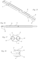
- the reinforcing element 27 is approximately H-shaped and has two legs 31, which are connected to each other via a central web 32. As Fig. 17 shows, are in the design variant according to the Figures 15 to 17
- the reinforcing element 27 encompasses the base elements 26 at the periphery over less than 180°, so that no positive connection is created.
- the reinforcing element 27 can be fixed to the base elements 26, for example, via a chemical bond such as adhesive or ultrasonic welding.
- the largest diameter d of the connecting section 21, 23 corresponds to the distance between the longitudinal sides of the base elements 26 arranged remote from one another. The largest diameter d is the greatest extent of the connecting section 21, 23 perpendicular to the longitudinal direction 50 of the connecting element 13.
- the reinforcing element 27 encompasses each base element 26 over an angle ⁇ of more than 180° of its circumference, resulting in a positive connection.
- the legs 31 are rounded at their ends. A design with edges according to Fig. 17 can be beneficial.
- the Figures 19 and 20 show schematically embodiments for a transition section 29, which extends between a connecting section 21 and the middle section 22.
- a corresponding transition section 29 is preferably also provided between the middle section 22 and the connecting section 23.
- the transition section 29 is conical, so that there is a continuous increase in the diameter from the connecting section 21 to the middle section 22.
- a curved course of the outer contour in the transition section 29 is provided in the longitudinal direction 50.
- the outer contour can be convex in section or, as in Fig. 20 indicated by a dashed line, are concave.
- the transition section 29 can be formed by a further element connected to the base element 26 and the reinforcing element 27 or can be integrally formed on the base element 26 or the reinforcing element 27.
- the rigidity in the central section 22 is at least 110%, in particular at least 130%, preferably at least 150% of the rigidity of each connecting section 21, 23.
- the partial cross-section 25 preferably forms at least 30%, in particular at least 50%, of the cross-section of the connecting element 13, 14, 15 in at least one connecting section 21, 23, in particular in both connecting sections.
- a profile 28 of any design can be provided in one or more further sections.
- the central section 22 consists at least partially of a material that has a higher fire resistance than the material of at least one connecting section 21 and 23. This can be achieved in particular by using a different material for the reinforcing element 27 than that of the base element 26.
- the central section 22 preferably consists at least partially, in particular entirely, of mineral material, in particular of high-strength or ultra-high-strength concrete or mortar.
- the reinforcing element 27 consists of concrete or mortar, in particular of high-strength or ultra-high-strength concrete or mortar.
- the central section 22 preferably consists at least partially of a material that has a lower thermal conductivity than the material of at least one connecting section 21 and 23.
- the connecting element 13, 14, 15 can also be used for other purposes, for example for fixing facade panels or as a reinforcement element for concrete.
Landscapes
- Engineering & Computer Science (AREA)
- Architecture (AREA)
- Physics & Mathematics (AREA)
- Electromagnetism (AREA)
- Civil Engineering (AREA)
- Structural Engineering (AREA)
- Building Environments (AREA)
Claims (14)
- Composant thermo-isolant destiné à être inséré dans un joint de séparation (4) entre une structure portée et une structure porteuse, en particulier entre une dalle de balcon (2) et un plafond de bâtiment (3), avec un corps isolant (5), dans lequel le corps isolant (5) possède une direction longitudinale (6) et des côtés longitudinaux (9, 10) s'étendant dans la direction longitudinale (6), se faisant face les uns les autres,dans lequel au moins un élément de liaison thermo-isolant (13, 14, 15) s'étend à travers le corps isolant (5), dans lequel l'élément de liaison (13, 14, 15) est réalisé en forme de barre et présente une première section de liaison (21), une deuxième section de liaison (23) et une section centrale (22) disposée entre les sections de liaison (21, 23), dans lequel la longueur (l3) de chaque section de liaison (21, 23) correspond au moins à 5 fois le diamètre le plus grand (d) de ladite section de liaison (21, 23), dans lequel l'élément de liaison (13, 14, 15) est constitué d'un matériau renforcé par des fibres et dans lequel au moins une section transversale partielle (25) de l'élément de liaison (13, 14, 15) s'étend en une partie et de bout en bout à travers la première section de liaison (21), la section centrale (22) et la deuxième section de liaison (23), dans lequel la rigidité de l'élément de liaison (13, 14, 15) dans la section centrale (22) est plus importante que dans les sections de liaison (21, 23), dans lequel la section centrale (22) dépasse du corps isolant (5) sur au moins un côté longitudinal (9, 10) du corps isolant (5),caractérisé en ce que l'élément de liaison (13, 14, 15) présente au moins un élément de base (26) et au moins un élément de renforcement (27) relié à l'élément de base (26), dans lequel l'au moins un élément de base (26) s'étend de bout en bout à travers les sections de liaison (21, 23) et la section centrale (22) et forme au moins une partie de la section transversale partielle (25), et dans lequel l'au moins un élément de renforcement (27) est disposé dans la section centrale (22) et ne s'étend pas dans les sections de liaison (21, 23).
- Composant selon la revendication 1,
caractérisé en ce que la rigidité dans la section centrale (22) est d'au moins 110 %, en particulier d'au moins 130 %, de manière préférée d'au moins 150 % de la rigidité de chaque section de liaison (21, 23). - Composant selon la revendication 1 ou 2,
caractérisé en ce que la section transversale partielle (25) forme dans au moins une section de liaison (21, 23), en particulier dans les deux sections de liaison (21, 23), au moins 30 % de la section transversale de l'élément de liaison (13, 14, 15). - Composant selon l'une quelconque des revendications 1 à 3,
caractérisé en ce que l'au moins un élément de base (26) et l'au moins un élément de renforcement (27) sont constitués du même matériau renforcé par des fibres. - Composant selon l'une quelconque des revendications 1 à 3,
caractérisé en ce que l'au moins un élément de base (26) et l'au moins un élément de renforcement (27) sont constitués de différents matériaux renforcés par des fibres. - Composant selon l'une quelconque des revendications 1 à 5,
caractérisé en ce que l'au moins un élément de renforcement (27) est bloqué par liaison de matière ou de manière mécanique sur l'au moins un élément de base (26). - Composant selon l'une quelconque des revendications 1 à 6,
caractérisé en ce que l'élément de liaison (13, 14, 15) est fabriqué dans un procédé de pultrusion. - Composant selon l'une quelconque des revendications 1 à 7,
caractérisé en ce que l'élément de liaison (13, 14, 15) présente, dans au moins une section de liaison (21, 23), un profilé (28) sur son côté extérieur. - Composant selon l'une quelconque des revendications 1 à 8,
caractérisé en ce que la section centrale (22) est constituée au moins en partie d'un matériau, qui présente une résistance au feu plus élevée que le matériau d'au moins une section de liaison (21, 23). - Composant selon l'une quelconque des revendications 1 à 9,
caractérisé en ce que la section centrale (22) est constituée au moins en partie, en particulier en totalité, d'un matériau minéral. - Composant selon l'une quelconque des revendications 1 à 10, caractérisé en ce que la section centrale (22) est constituée au moins en partie d'un matériau, qui présente une conductivité thermique plus basse que le matériau d'au moins une section de liaison (21, 23).
- Composant selon l'une quelconque des revendications 1 à 11, caractérisé en ce que le matériau renforcé par des fibres présente des fibres de verre et/ou des fibres de basalte et/ou des fibres de carbone et/ou des fibres d'aramide.
- Composant selon l'une quelconque des revendications 1 à 12, caractérisé en ce qu'au moins une section de liaison (21, 23) est reliée à la section centrale (22) par l'intermédiaire d'une section de transition (29), dans lequel la section transversale de l'élément de liaison (13, 14, 15) s'agrandit de manière continue depuis la section de liaison (21, 23) vers la section centrale (22) dans la section de transition (29).
- Composant selon l'une quelconque des revendications 1 à 13, caractérisé en ce que la section centrale (22) dépasse du corps isolant (5) sur les deux côtés longitudinaux (9, 10) du corps isolant (5).
Priority Applications (2)
| Application Number | Priority Date | Filing Date | Title |
|---|---|---|---|
| PL19170477.4T PL3730708T3 (pl) | 2019-04-23 | 2019-04-23 | Termoizolacyjny element łączący i termoizolacyjny element budowlany |
| EP19170477.4A EP3730708B1 (fr) | 2019-04-23 | 2019-04-23 | Élément de raccordement thermo-isolant et composant thermo-isolant |
Applications Claiming Priority (1)
| Application Number | Priority Date | Filing Date | Title |
|---|---|---|---|
| EP19170477.4A EP3730708B1 (fr) | 2019-04-23 | 2019-04-23 | Élément de raccordement thermo-isolant et composant thermo-isolant |
Publications (3)
| Publication Number | Publication Date |
|---|---|
| EP3730708A1 EP3730708A1 (fr) | 2020-10-28 |
| EP3730708C0 EP3730708C0 (fr) | 2025-06-04 |
| EP3730708B1 true EP3730708B1 (fr) | 2025-06-04 |
Family
ID=66248557
Family Applications (1)
| Application Number | Title | Priority Date | Filing Date |
|---|---|---|---|
| EP19170477.4A Active EP3730708B1 (fr) | 2019-04-23 | 2019-04-23 | Élément de raccordement thermo-isolant et composant thermo-isolant |
Country Status (2)
| Country | Link |
|---|---|
| EP (1) | EP3730708B1 (fr) |
| PL (1) | PL3730708T3 (fr) |
Citations (1)
| Publication number | Priority date | Publication date | Assignee | Title |
|---|---|---|---|---|
| EP3656938A1 (fr) * | 2018-11-20 | 2020-05-27 | Schöck Bauteile GmbH | Composant permettant le raccordement à pont thermique faible d'une partie extérieure en saillie à une enveloppe de bâtiment |
Family Cites Families (5)
| Publication number | Priority date | Publication date | Assignee | Title |
|---|---|---|---|---|
| DE4214704A1 (de) * | 1992-05-02 | 1993-11-04 | Schoeck Bauteile Gmbh | Bauelement zur waermedaemmung bei gebaeuden |
| WO2005035892A1 (fr) | 2003-10-10 | 2005-04-21 | Hitek Construction Ag | Dispositif comprenant une barre en plastique renforce par des fibres et servant a transmettre une charge a travers une couche calorifuge |
| WO2016007479A1 (fr) * | 2014-07-07 | 2016-01-14 | Composite Technologies Corporation | Élément de transfert de compression |
| BE1023762B1 (nl) | 2016-01-12 | 2017-07-14 | Plakabeton Nv | Constructie-element voor het realiseren van een verbinding tussen thermisch geisoleerde delen van een gebouw |
| DE102016113558A1 (de) * | 2016-07-22 | 2018-01-25 | Schöck Bauteile GmbH | Bauelement zur Wärmedämmung |
-
2019
- 2019-04-23 PL PL19170477.4T patent/PL3730708T3/pl unknown
- 2019-04-23 EP EP19170477.4A patent/EP3730708B1/fr active Active
Patent Citations (1)
| Publication number | Priority date | Publication date | Assignee | Title |
|---|---|---|---|---|
| EP3656938A1 (fr) * | 2018-11-20 | 2020-05-27 | Schöck Bauteile GmbH | Composant permettant le raccordement à pont thermique faible d'une partie extérieure en saillie à une enveloppe de bâtiment |
Also Published As
| Publication number | Publication date |
|---|---|
| EP3730708A1 (fr) | 2020-10-28 |
| PL3730708T3 (pl) | 2025-09-01 |
| EP3730708C0 (fr) | 2025-06-04 |
Similar Documents
| Publication | Publication Date | Title |
|---|---|---|
| EP2653625B1 (fr) | Composant à isolation thermique | |
| EP3336269B1 (fr) | Élément de construction destiné a l'isolation thermique | |
| DE2216302A1 (de) | Verbindungselement fuer bewehrungsstaebe von betonfertigbauteilen | |
| DE19711813C2 (de) | Thermisch isolierendes Bauelement | |
| EP2824249B1 (fr) | Composant à isolation thermique | |
| DE4102332A1 (de) | Balkonanschluss | |
| EP2436845B1 (fr) | Dispositif de raccordement forcé d'un composant sur un corps de construction, notamment d'un balcon sur un bâtiment | |
| EP3730708B1 (fr) | Élément de raccordement thermo-isolant et composant thermo-isolant | |
| EP1680559A1 (fr) | Dispositif comprenant une barre en plastique renforce par des fibres et servant a transmettre une charge a travers une couche calorifuge | |
| EP0086751B1 (fr) | Ancre pouvant être soumise à la traction | |
| WO2008113347A2 (fr) | Élément d'isolation thermique | |
| DE9318354U1 (de) | Balkonanschluß | |
| DE102006052648A1 (de) | Traganker zur Befestigung von Fassadenelementen an einer Gebäudewand | |
| EP2876224A1 (fr) | Dalle de plafond ou de toit conçue en tant que construction composite en acier/béton | |
| DE19519614C2 (de) | Kragplatten- und/oder Fugenelement für bewehrte Baukonstruktionen | |
| EP0745733A1 (fr) | Elément de dalle en porte-à-faux et/ou élément de joint pour ouvrages de construction armés | |
| EP1457619A1 (fr) | Elément d'armature pour constructions en béton | |
| EP0745734A1 (fr) | Elément de dalle en porte-à-faux et/ou élément de joint pour ouvrages de construction armés | |
| EP1703036B1 (fr) | Élément de construction pour armature de cisaillement et de poinçonnement | |
| EP2998454A1 (fr) | Dispositif destine a relier deux parties de batiment separees par un joint | |
| EP4050170B1 (fr) | Construction pourvue d'élément thermoisolant | |
| DE102020114611B3 (de) | Schalungsanordnung | |
| EP3733988B1 (fr) | Élément de construction thermo-isolant | |
| WO2008113348A2 (fr) | Élément d'isolation thermique | |
| EP2708760B1 (fr) | Élément d'isolation d'un agencement d'ancrage mural |
Legal Events
| Date | Code | Title | Description |
|---|---|---|---|
| PUAI | Public reference made under article 153(3) epc to a published international application that has entered the european phase |
Free format text: ORIGINAL CODE: 0009012 |
|
| STAA | Information on the status of an ep patent application or granted ep patent |
Free format text: STATUS: THE APPLICATION HAS BEEN PUBLISHED |
|
| AK | Designated contracting states |
Kind code of ref document: A1 Designated state(s): AL AT BE BG CH CY CZ DE DK EE ES FI FR GB GR HR HU IE IS IT LI LT LU LV MC MK MT NL NO PL PT RO RS SE SI SK SM TR |
|
| AX | Request for extension of the european patent |
Extension state: BA ME |
|
| STAA | Information on the status of an ep patent application or granted ep patent |
Free format text: STATUS: REQUEST FOR EXAMINATION WAS MADE |
|
| 17P | Request for examination filed |
Effective date: 20210422 |
|
| RBV | Designated contracting states (corrected) |
Designated state(s): AL AT BE BG CH CY CZ DE DK EE ES FI FR GB GR HR HU IE IS IT LI LT LU LV MC MK MT NL NO PL PT RO RS SE SI SK SM TR |
|
| RAP3 | Party data changed (applicant data changed or rights of an application transferred) |
Owner name: LEVIAT GMBH |
|
| STAA | Information on the status of an ep patent application or granted ep patent |
Free format text: STATUS: EXAMINATION IS IN PROGRESS |
|
| P01 | Opt-out of the competence of the unified patent court (upc) registered |
Effective date: 20230522 |
|
| 17Q | First examination report despatched |
Effective date: 20230615 |
|
| GRAP | Despatch of communication of intention to grant a patent |
Free format text: ORIGINAL CODE: EPIDOSNIGR1 |
|
| STAA | Information on the status of an ep patent application or granted ep patent |
Free format text: STATUS: GRANT OF PATENT IS INTENDED |
|
| INTG | Intention to grant announced |
Effective date: 20240909 |
|
| GRAJ | Information related to disapproval of communication of intention to grant by the applicant or resumption of examination proceedings by the epo deleted |
Free format text: ORIGINAL CODE: EPIDOSDIGR1 |
|
| STAA | Information on the status of an ep patent application or granted ep patent |
Free format text: STATUS: EXAMINATION IS IN PROGRESS |
|
| GRAP | Despatch of communication of intention to grant a patent |
Free format text: ORIGINAL CODE: EPIDOSNIGR1 |
|
| STAA | Information on the status of an ep patent application or granted ep patent |
Free format text: STATUS: GRANT OF PATENT IS INTENDED |
|
| GRAS | Grant fee paid |
Free format text: ORIGINAL CODE: EPIDOSNIGR3 |
|
| INTC | Intention to grant announced (deleted) | ||
| INTG | Intention to grant announced |
Effective date: 20241211 |
|
| RIN1 | Information on inventor provided before grant (corrected) |
Inventor name: BRANCO, MIGUEL Inventor name: FUELLSACK-KOEDITZ, RAIMO Inventor name: GARKE, ROBERT Inventor name: HEIDOLF, THORSTEN Inventor name: REMY, OLIVIER |
|
| GRAA | (expected) grant |
Free format text: ORIGINAL CODE: 0009210 |
|
| STAA | Information on the status of an ep patent application or granted ep patent |
Free format text: STATUS: THE PATENT HAS BEEN GRANTED |
|
| AK | Designated contracting states |
Kind code of ref document: B1 Designated state(s): AL AT BE BG CH CY CZ DE DK EE ES FI FR GB GR HR HU IE IS IT LI LT LU LV MC MK MT NL NO PL PT RO RS SE SI SK SM TR |
|
| REG | Reference to a national code |
Ref country code: GB Ref legal event code: FG4D Free format text: NOT ENGLISH |
|
| REG | Reference to a national code |
Ref country code: CH Ref legal event code: EP |
|
| REG | Reference to a national code |
Ref country code: DE Ref legal event code: R096 Ref document number: 502019013398 Country of ref document: DE |
|
| REG | Reference to a national code |
Ref country code: IE Ref legal event code: FG4D Free format text: LANGUAGE OF EP DOCUMENT: GERMAN |
|
| U01 | Request for unitary effect filed |
Effective date: 20250605 |
|
| P04 | Withdrawal of opt-out of the competence of the unified patent court (upc) registered |
Free format text: CASE NUMBER: APP_27227/2025 Effective date: 20250607 |
|
| U07 | Unitary effect registered |
Designated state(s): AT BE BG DE DK EE FI FR IT LT LU LV MT NL PT RO SE SI Effective date: 20250612 |
|
| PG25 | Lapsed in a contracting state [announced via postgrant information from national office to epo] |
Ref country code: ES Free format text: LAPSE BECAUSE OF FAILURE TO SUBMIT A TRANSLATION OF THE DESCRIPTION OR TO PAY THE FEE WITHIN THE PRESCRIBED TIME-LIMIT Effective date: 20250604 |
|
| PG25 | Lapsed in a contracting state [announced via postgrant information from national office to epo] |
Ref country code: GR Free format text: LAPSE BECAUSE OF FAILURE TO SUBMIT A TRANSLATION OF THE DESCRIPTION OR TO PAY THE FEE WITHIN THE PRESCRIBED TIME-LIMIT Effective date: 20250905 Ref country code: NO Free format text: LAPSE BECAUSE OF FAILURE TO SUBMIT A TRANSLATION OF THE DESCRIPTION OR TO PAY THE FEE WITHIN THE PRESCRIBED TIME-LIMIT Effective date: 20250904 |
|
| PG25 | Lapsed in a contracting state [announced via postgrant information from national office to epo] |
Ref country code: HR Free format text: LAPSE BECAUSE OF FAILURE TO SUBMIT A TRANSLATION OF THE DESCRIPTION OR TO PAY THE FEE WITHIN THE PRESCRIBED TIME-LIMIT Effective date: 20250604 |
|
| PG25 | Lapsed in a contracting state [announced via postgrant information from national office to epo] |
Ref country code: RS Free format text: LAPSE BECAUSE OF FAILURE TO SUBMIT A TRANSLATION OF THE DESCRIPTION OR TO PAY THE FEE WITHIN THE PRESCRIBED TIME-LIMIT Effective date: 20250904 |
|
| PG25 | Lapsed in a contracting state [announced via postgrant information from national office to epo] |
Ref country code: IS Free format text: LAPSE BECAUSE OF FAILURE TO SUBMIT A TRANSLATION OF THE DESCRIPTION OR TO PAY THE FEE WITHIN THE PRESCRIBED TIME-LIMIT Effective date: 20251004 |
|
| PG25 | Lapsed in a contracting state [announced via postgrant information from national office to epo] |
Ref country code: SM Free format text: LAPSE BECAUSE OF FAILURE TO SUBMIT A TRANSLATION OF THE DESCRIPTION OR TO PAY THE FEE WITHIN THE PRESCRIBED TIME-LIMIT Effective date: 20250604 |
|
| PG25 | Lapsed in a contracting state [announced via postgrant information from national office to epo] |
Ref country code: CZ Free format text: LAPSE BECAUSE OF FAILURE TO SUBMIT A TRANSLATION OF THE DESCRIPTION OR TO PAY THE FEE WITHIN THE PRESCRIBED TIME-LIMIT Effective date: 20250604 |
|
| PG25 | Lapsed in a contracting state [announced via postgrant information from national office to epo] |
Ref country code: SK Free format text: LAPSE BECAUSE OF FAILURE TO SUBMIT A TRANSLATION OF THE DESCRIPTION OR TO PAY THE FEE WITHIN THE PRESCRIBED TIME-LIMIT Effective date: 20250604 |
|
| PLBE | No opposition filed within time limit |
Free format text: ORIGINAL CODE: 0009261 |
|
| STAA | Information on the status of an ep patent application or granted ep patent |
Free format text: STATUS: NO OPPOSITION FILED WITHIN TIME LIMIT |
|
| REG | Reference to a national code |
Ref country code: CH Ref legal event code: L10 Free format text: ST27 STATUS EVENT CODE: U-0-0-L10-L00 (AS PROVIDED BY THE NATIONAL OFFICE) Effective date: 20260416 |
|
| PGFP | Annual fee paid to national office [announced via postgrant information from national office to epo] |
Ref country code: PL Payment date: 20260326 Year of fee payment: 8 |