EP1564367B1 - Trepan de forage - Google Patents
Trepan de forage Download PDFInfo
- Publication number
- EP1564367B1 EP1564367B1 EP04003435A EP04003435A EP1564367B1 EP 1564367 B1 EP1564367 B1 EP 1564367B1 EP 04003435 A EP04003435 A EP 04003435A EP 04003435 A EP04003435 A EP 04003435A EP 1564367 B1 EP1564367 B1 EP 1564367B1
- Authority
- EP
- European Patent Office
- Prior art keywords
- drill
- mixing element
- accordance
- earth displacement
- head
- Prior art date
- Legal status (The legal status is an assumption and is not a legal conclusion. Google has not performed a legal analysis and makes no representation as to the accuracy of the status listed.)
- Expired - Lifetime
Links
- 238000006073 displacement reaction Methods 0.000 title claims abstract description 19
- 238000000034 method Methods 0.000 claims abstract description 6
- 238000005553 drilling Methods 0.000 claims description 53
- 239000012530 fluid Substances 0.000 claims description 31
- 238000004519 manufacturing process Methods 0.000 abstract description 2
- 239000002689 soil Substances 0.000 description 21
- 239000000463 material Substances 0.000 description 16
- 239000000203 mixture Substances 0.000 description 10
- 239000000654 additive Substances 0.000 description 2
- 230000001050 lubricating effect Effects 0.000 description 2
- 239000002245 particle Substances 0.000 description 2
- 239000011148 porous material Substances 0.000 description 2
- 229910000831 Steel Inorganic materials 0.000 description 1
- 239000004568 cement Substances 0.000 description 1
- 239000000470 constituent Substances 0.000 description 1
- 230000000694 effects Effects 0.000 description 1
- 239000004570 mortar (masonry) Substances 0.000 description 1
- 230000008092 positive effect Effects 0.000 description 1
- 238000005086 pumping Methods 0.000 description 1
- 230000003716 rejuvenation Effects 0.000 description 1
- 238000005096 rolling process Methods 0.000 description 1
- 239000010959 steel Substances 0.000 description 1
- 238000010408 sweeping Methods 0.000 description 1
- XLYOFNOQVPJJNP-UHFFFAOYSA-N water Substances O XLYOFNOQVPJJNP-UHFFFAOYSA-N 0.000 description 1
Images

Classifications
-
- E—FIXED CONSTRUCTIONS
- E21—EARTH OR ROCK DRILLING; MINING
- E21B—EARTH OR ROCK DRILLING; OBTAINING OIL, GAS, WATER, SOLUBLE OR MELTABLE MATERIALS OR A SLURRY OF MINERALS FROM WELLS
- E21B10/00—Drill bits
- E21B10/44—Bits with helical conveying portion, e.g. screw type bits; Augers with leading portion or with detachable parts
-
- E—FIXED CONSTRUCTIONS
- E21—EARTH OR ROCK DRILLING; MINING
- E21B—EARTH OR ROCK DRILLING; OBTAINING OIL, GAS, WATER, SOLUBLE OR MELTABLE MATERIALS OR A SLURRY OF MINERALS FROM WELLS
- E21B21/00—Methods or apparatus for flushing boreholes, e.g. by use of exhaust air from motor
- E21B21/06—Arrangements for treating drilling fluids outside the borehole
- E21B21/062—Arrangements for treating drilling fluids outside the borehole by mixing components
-
- E—FIXED CONSTRUCTIONS
- E02—HYDRAULIC ENGINEERING; FOUNDATIONS; SOIL SHIFTING
- E02D—FOUNDATIONS; EXCAVATIONS; EMBANKMENTS; UNDERGROUND OR UNDERWATER STRUCTURES
- E02D5/00—Bulkheads, piles, or other structural elements specially adapted to foundation engineering
- E02D5/72—Pile shoes
-
- E—FIXED CONSTRUCTIONS
- E21—EARTH OR ROCK DRILLING; MINING
- E21B—EARTH OR ROCK DRILLING; OBTAINING OIL, GAS, WATER, SOLUBLE OR MELTABLE MATERIALS OR A SLURRY OF MINERALS FROM WELLS
- E21B33/00—Sealing or packing boreholes or wells
- E21B33/10—Sealing or packing boreholes or wells in the borehole
- E21B33/13—Methods or devices for cementing, for plugging holes, crevices or the like
- E21B33/138—Plastering the borehole wall; Injecting into the formation
Definitions
- the present invention relates to a Erdverdrfitungsbohrer according to the preamble of claim 1 (see, DE 195 30 718 G).
- a drilling fluid is usually introduced into the drill channel in the area of the drill head.
- a drilling fluid may for example be water, but often consists of a mixture of cement and mortar, although other additives can be used.
- the lubricating action of drilling fluid mixed with constituents of the soil material allows the drill pipe to be drilled to a desired depth. After creating the drilling channel, it can be filled with concrete to form a pile.
- the mixing element may be dimensioned such that it does not protrude radially beyond the drill head and in particular extends radially outward approximately to the largest radius of the drill head. In this way, it is ensured that the mixing element does not undesirably increase the drilling channel.
- a radial extent to about the largest radius of the drill head ensures that a thorough mixing of drilling fluid and soil material over the entire cross section of the annulus takes place.
- the mixing element is arranged directly above the drill head.
- Such an embodiment is particularly advantageous when the drilling fluid exits through one or more openings in the region of the drill head in the wellbore. In this way, the mixing can be done immediately above the drill head.
- the mixing element is formed so that between this and the drill pipe, in particular a closed volume is included.
- the mixing element is designed as a body, whereby a particularly good mixing is achieved.
- the mixing element has at least one wedge surface, which forms a tapered region in cross section with the wall of a drilling channel formed by the drill head.
- the wedge surface ensures that upon rotation of the drill pipe, the mixture of drilling fluid and soil material is forced into the tapered region, wherein the mixture is then registered by the rotational movement of the wedge surface in the wall of the drilling channel. In this way, as it were a plastering of the drilling channel can be achieved by the mixed by the mixing element mixture of drilling fluid and soil material is pressed into the wall of the drilling channel. This provides a highly stable bore that does not break down and prevents drilling fluid from leaking into the surrounding soil.
- the mixing element may have a convex outer surface, which is in particular formed symmetrically.
- a particularly good introduction of the mixed material is achieved in the wall of the drilling channel.
- Particularly good results have resulted from the fact that at least one outer surface was provided on the mixing element, which was arranged approximately tangentially to the drill pipe.
- the mixing element may in principle be arranged parallel to the drilling axis, but may also be arranged obliquely on the drill pipe, so that a plane passing through the center axis of the drill pipe forms an angle with the longitudinal axis of the mixing element.
- the longitudinal extent of the mixing element can vary. Good results have been found when the mixing element is about one and a half to two and a half times the diameter of the drill pipe.
- the drill is drilled into the ground, introducing drilling fluid into the annulus formed between the wellbore and the wellbore, with the drilling fluid mixed above the wellhead.
- the introduction of the drilling fluid preferably takes place via the tip of the drill head so that it initially exits into the borehole formed by the drill head and then fills the annular space between the drill pipe and the borehole.
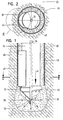
- the Erdverdrfitungsbohrer shown in Fig. 1 has a circular cylindrical drill pipe 10, at the lower end of a drill head 12 is welded.
- the illustrated enlarged in Figure 4 drill head 12 has at its rear end an annular shank portion 14 into which the front end of the drill pipe 10 is inserted, whereupon drill pipe 10 and drill head 12 can be connected to each other by means of a welded joint 16.
- the shaft portion 14 is adjoined by a cone-shaped tip portion 18, which is integrally formed with the shaft portion 14.
- a plurality of helical ribs 20, 21, 22 and 23 are provided, wherein the ribs 20 and 21 project radially from the shaft portion 14 and the ribs 22 and 23 protrude in the axial direction of the tip portion 18.
- spaced-apart teeth 24 which point in the axial direction of the drill head 12, which coincides with the drilling direction X (FIG. 1).
- the entire drill head 12 is integrally formed.
- the drill head 12 as well as the drill pipe 10 are made of steel.
- the radius of the drill pipe 10 is smaller than the largest radius of the drill head 12, so that when inserting the ErdverdrDeutschungsbohrers in soil material between the resulting drill channel and the drill pipe 10, an annular space 30 is formed.
- Fig. 1 also illustrates that both the resulting in the region of the drill head 12 wellbore 32 as well as the annular channel 30 are filled with a mixture of drilling fluid and particles of the soil material.
- the drilling fluid is guided through a pipe 34 disposed inside the drill pipe 10 in the region of the foremost end of the drill head 12 and occurs from there via radial outlet channels 36 into the borehole 32.
- the exiting drilling fluid 38 mixes with particles of the soil material and fills the wellbore 32 as well as the wellbore 30.
- a mixing element 40 is provided immediately above the drill head 12, which extends in the longitudinal direction X of the drill pipe and which does not project radially beyond the drill head 12, but extends radially outward approximately to the largest radius of the drill head 12.
- the mixing element 40 is a groove-shaped component whose radius is smaller than that of the drill pipe 10.
- the mixing element 40 is welded in the illustrated embodiment to the outer shell of the drill pipe 10 and closed at its top and bottom, so that between the mixing element 40 and the drill pipe 10, a closed volume is included.
- Fig. 3b shows another embodiment of a mixing element 40 '.
- the mixing element 40 ' is formed by an angle-shaped component, whose two legs are the same length and enclose an angle of about 115 ° with each other.
- the position of the mixing element 40 'on the drill pipe 10 is the same as that of the mixing element 40.
- the mixing element according to the invention can either have a convex outer circumferential surface (FIG. 3 a) or the mixing element can have two outer surfaces converging towards one another (FIG. 3 b).
- the mixing element has on its outer side a surface 42 or 42 ', which extends approximately tangentially to the outer casing of the drill pipe 10, and which serves as a wedge surface, since it with the wall of the drilling head 30 formed by a drill forms a tapered region 44.
- the mixture consisting of drilling fluid and soil material is mixed on the one hand in the annular space 30 and, on the other hand, introduced into the wall of the drilling channel so that it is stabilized, which will be described in more detail below during a rotation of the Erdverdrfitungsbohrers.
- the mixing element 40 provides intimate mixing of drilling fluid and soil material.
- the mixing element 40 ensures that the mixture located in the annular space 30 is pressed or entered into the wall of the drilling channel by the wedge surface 42 sweeping the mixture located in the region 44 into the wall of the drilling channel.
- the pores 46 present in the surrounding soil material are sealed and the wall of the annular space 30 or of the drilling channel is plastered, as it were, and thereby sealed and stabilized.
- the drill channel has a stabilized wall portion 48 which simultaneously seals the surrounding soil, so that the annulus above the drill head 12 remains filled with drilling fluid, without this penetrates into the surrounding soil and seeps.
- This is on the one hand ensures that the drill channel remains stable and does not collapse.
- it is ensured that the friction-reducing effect of the drilling fluid over the entire length of the drill pipe is maintained, whereby the torque required for drilling is considerably reduced.
- the wall thickness of the drill pipe 12 can remain within reasonable limits.
- mixing element 40, 40 ' also a certain imbalance is present, which imposes on the drill a certain rolling motion, which has a positive effect during drilling.
- a plurality of mixing elements 40 and 40 ' can be provided.
- the mixing element can be arranged obliquely on the outer circumference of the drill pipe.
- both drill pipe as well as mixing element can also be made of plastic.
- the mixing element may be curved or curved in the axial direction.
Landscapes
- Engineering & Computer Science (AREA)
- Mining & Mineral Resources (AREA)
- Life Sciences & Earth Sciences (AREA)
- Geology (AREA)
- General Life Sciences & Earth Sciences (AREA)
- Environmental & Geological Engineering (AREA)
- Fluid Mechanics (AREA)
- Physics & Mathematics (AREA)
- Geochemistry & Mineralogy (AREA)
- Mechanical Engineering (AREA)
- Structural Engineering (AREA)
- Paleontology (AREA)
- Civil Engineering (AREA)
- General Engineering & Computer Science (AREA)
- Earth Drilling (AREA)
- Processing Of Stones Or Stones Resemblance Materials (AREA)
- Drilling Tools (AREA)
Claims (15)
- Trépan de forage comportant un tube de forage (10) et une tête de forage (12) fixée de façon inamovible à son extrémité, le rayon du tube de forage (10) étant inférieur au plus grand rayon de la tête de forage (12), au moins un élément mélangeur (40, 40') étant prévu à la périphérie extérieure du tube de forage (10) et s'étendant dans sa direction longitudinale (X),
caractérisé en ce que
le tube de forage (10) s'étend en ligne droite jusqu'à la tête de forage (12),
l'élément mélangeur (40, 40') est fixé de façon rigide à la périphérie extérieure du tube de forage (10), et
sur la tête de forage (12) est prévue au moins une nervure (20, 21) dépassant radialement et en forme d'hélice. - Trépan de forage selon la revendication 1,
caractérisé en ce que
l'élément mélangeur (40, 40') ne dépasse pas radialement au-delà de la tête de forage (12) et s'étend en particulier radialement vers l'extérieur approximativement jusqu'au plus grand rayon de la tête de forage. - Trépan de forage selon la revendication 1,
caractérisé en ce que
l'élément mélangeur (40, 40') est agencé directement au-dessus de la tête de forage (12). - Trépan de forage selon la revendication 1,
caractérisé en ce que
l'élément mélangeur (40, 40') enferme entre lui-même et le tube de forage (10) un volume en particulier fermé. - Trépan de forage selon la revendication 1,
caractérisé en ce que
l'élément mélangeur (40, 40') est réalisé symétrique en coupe longitudinale et/ou transversale. - Trépan de forage selon la revendication 1,
caractérisé en ce que
l'élément mélangeur (40, 40') comprend au moins une surface en coin (42, 42') qui forme, vue en coupe transversale, conjointement avec la paroi (48) d'un canal de forage formé par la tête de forage, une zone (44) qui va en se rétrécissant. - Trépan de forage selon la revendication 1,
caractérisé en ce que
l'élément mélangeur (40) présente une surface extérieure convexe. - Trépan de forage selon la revendication 1,
caractérisé en ce que
l'élément mélangeur (40, 40') présente au moins une surface extérieure qui s'étend approximativement tangentiellement au tube de forage (10). - Trépan de forage selon la revendication 1,
caractérisé en ce que
un plan passant par l'axe médian (X) du tube de forage forme un angle avec l'axe longitudinal de l'élément mélangeur. - Trépan de forage selon la revendication 1,
caractérisé en ce que
l'extension longitudinale de l'élément mélangeur (40, 40') est d'environ 150 à 250 % du diamètre du tube de forage. - Trépan de forage selon la revendication 1,
caractérisé en ce que
la tête de forage (12) comprend au moins une nervure (20 - 23) qui fait saillie axialement et sur la face inférieure de laquelle sont prévues des dents individuelles (24) s'étendant en direction de forage (X). - Trépan de forage selon la revendication 1,
caractérisé en ce que
la nervure (20, 21) dépassant radialement présente sur sa face inférieure des dents individuelles (24) qui s'étendent dans la direction de forage (X). - Procédé pour réaliser un trou de forage au moyen d'un trépan de forage selon l'une au moins des revendications précédentes, dans lequel on enfonce le trépan de forage dans le sol, on introduit un fluide de forage dans l'espace annulaire qui se forme entre le trou de forage et le canal de forage, et on mélange ce fluide de forage au-dessus de la tête de forage.
- Procédé selon la revendication 13,
caractérisé en ce que
l'on introduit le fluide de forage en supplément dans la paroi du canal de forage, en particulier à la presse. - Procédé selon la revendication 13,
caractérisé en ce que
l'on mène le fluide de forage à travers le tube de forage et la tête de forage jusque dans le trou de forage.
Priority Applications (3)
| Application Number | Priority Date | Filing Date | Title |
|---|---|---|---|
| AT04003435T ATE338195T1 (de) | 2004-02-16 | 2004-02-16 | Erdverdrängungsbohrer |
| EP04003435A EP1564367B1 (fr) | 2004-02-16 | 2004-02-16 | Trepan de forage |
| DE502004001336T DE502004001336D1 (de) | 2004-02-16 | 2004-02-16 | Erdverdrängungsbohrer |
Applications Claiming Priority (1)
| Application Number | Priority Date | Filing Date | Title |
|---|---|---|---|
| EP04003435A EP1564367B1 (fr) | 2004-02-16 | 2004-02-16 | Trepan de forage |
Publications (2)
| Publication Number | Publication Date |
|---|---|
| EP1564367A1 EP1564367A1 (fr) | 2005-08-17 |
| EP1564367B1 true EP1564367B1 (fr) | 2006-08-30 |
Family
ID=34684703
Family Applications (1)
| Application Number | Title | Priority Date | Filing Date |
|---|---|---|---|
| EP04003435A Expired - Lifetime EP1564367B1 (fr) | 2004-02-16 | 2004-02-16 | Trepan de forage |
Country Status (3)
| Country | Link |
|---|---|
| EP (1) | EP1564367B1 (fr) |
| AT (1) | ATE338195T1 (fr) |
| DE (1) | DE502004001336D1 (fr) |
Families Citing this family (2)
| Publication number | Priority date | Publication date | Assignee | Title |
|---|---|---|---|---|
| ATE442511T1 (de) * | 2007-07-06 | 2009-09-15 | Bauer Maschinen Gmbh | Erdbohrer |
| BE1023794B1 (nl) | 2016-07-14 | 2017-07-26 | Proferro Nv | Een tip met uitsteeksels voor een grondverplaatsingsoperatie voor een funderingspaal |
Family Cites Families (9)
| Publication number | Priority date | Publication date | Assignee | Title |
|---|---|---|---|---|
| US3255833A (en) * | 1963-10-10 | 1966-06-14 | Texaco Development Corp | Drill bit auxiliary |
| US3799279A (en) * | 1972-09-25 | 1974-03-26 | R Farris | Optionally stabilized drilling tool |
| DE19530718C1 (de) * | 1995-08-21 | 1996-09-26 | Bauer Spezialtiefbau | Bohrvorrichtung und Verfahren zur Herstellung eines Pfahles in einem Bohrloch |
| AUPO114996A0 (en) * | 1996-07-22 | 1996-08-15 | Jarmyn, Gary Wayne | Identification and warning system for underground conduits or pipes laid by the 'directional drilling' method |
| DE19749409A1 (de) * | 1997-05-04 | 1999-05-12 | Gerd Hoermansdoerfer | Bohrverfahren und Bohrkopf |
| DE19859928C1 (de) * | 1998-12-23 | 2000-08-31 | Ludwig Pfeiffer Hoch Und Tiefb | Verfahren und Schutzrohr zum Erneuern einer im Erdreich verlegten Rohrleitung |
| GB2365463B (en) * | 2000-08-01 | 2005-02-16 | Renovus Ltd | Drilling method |
| DE10150278B4 (de) * | 2001-10-12 | 2006-07-06 | Tracto-Technik Gmbh | Verfahren und Vorrichtung zum Bodenstabilisieren |
| DE10205826A1 (de) * | 2001-10-18 | 2003-05-08 | Fitr Ges Fuer Innovation Im Ti | Verfahren zum Verlegen von Rohren mittels unterirdischem Rohrvortrieb |
-
2004
- 2004-02-16 EP EP04003435A patent/EP1564367B1/fr not_active Expired - Lifetime
- 2004-02-16 DE DE502004001336T patent/DE502004001336D1/de not_active Expired - Fee Related
- 2004-02-16 AT AT04003435T patent/ATE338195T1/de not_active IP Right Cessation
Also Published As
| Publication number | Publication date |
|---|---|
| ATE338195T1 (de) | 2006-09-15 |
| EP1564367A1 (fr) | 2005-08-17 |
| DE502004001336D1 (de) | 2006-10-12 |
Similar Documents
| Publication | Publication Date | Title |
|---|---|---|
| DE10017763B4 (de) | Gebirgsanker | |
| DE2941769C2 (de) | Verfahren zum Setzen eines Ankerbolzens und Ankerbolzen | |
| EP2257690B1 (fr) | Cheville autoforeuse protégée contre la corrosion, et bloc d'éléments de cheville, et leur procédé de fabrication | |
| EP0368838B1 (fr) | Dispositif de consolidation de formations géologiques non ou peu stables | |
| EP0588143B1 (fr) | Trépan de forage pour former un pieu de béton dans le sol | |
| EP0371463B1 (fr) | Procédé pour mettre en place un ancrage et ancrage de forage d'injection de mise en oeuvre du procédé | |
| DE102011085187B3 (de) | Bohrer und Herstellungsverfahren für einen Bohrer | |
| DE102013111350A1 (de) | Aufweitwerkzeug und Vorrichtung zum Aufweiten einer im Erdreich vorhandenen Durchgangsöffnung | |
| DE3738420C2 (fr) | ||
| DE3624202C2 (de) | Spiralbohrer | |
| DE2343080A1 (de) | Bohrverfahren und vorrichtung zu seiner durchfuehrung | |
| DE102011077595A1 (de) | Ankerschraube | |
| EP2065559A2 (fr) | Tige d'ancrage autoperceuse | |
| EP1564367A1 (fr) | Trepan de forage | |
| CH693934A5 (de) | Verfahren zum Bohren und Verfuellen von Loechern. | |
| EP3112580B1 (fr) | Procédé et dispositif pour la formation d'une canalisation souterraine | |
| WO2019086164A1 (fr) | Agencement de foret à vis sans fin | |
| DE2711899A1 (de) | Vorrichtung fuer die bodeninjektion bei hochdruck-bodenvermoertelungen und pfahlgruendungen | |
| DE19530718C1 (de) | Bohrvorrichtung und Verfahren zur Herstellung eines Pfahles in einem Bohrloch | |
| DE19744322C1 (de) | Verfahren und Vorrichtung zum Einbringen von Ankern in sandigen, kiesigen oder bindigen Böden | |
| DE3737259C1 (en) | Apparatus and method for high-pressure injection | |
| DE102006023799B4 (de) | Vorrichtung zur Herstellung von Gründungselementen | |
| DE19503177C1 (de) | Verfahren zur Herstellung von Bohrpfählen | |
| DE102004005238B3 (de) | Kleinbohrschnecke | |
| DE69516915T2 (de) | Werkzeug und Verfahren zum Bohren ohne Erdaustrag und Füllen des Bohrloches mit Beton |
Legal Events
| Date | Code | Title | Description |
|---|---|---|---|
| PUAI | Public reference made under article 153(3) epc to a published international application that has entered the european phase |
Free format text: ORIGINAL CODE: 0009012 |
|
| 17P | Request for examination filed |
Effective date: 20050530 |
|
| AK | Designated contracting states |
Kind code of ref document: A1 Designated state(s): AT BE BG CH CY CZ DE DK EE ES FI FR GB GR HU IE IT LI LU MC NL PT RO SE SI SK TR |
|
| AX | Request for extension of the european patent |
Extension state: AL LT LV MK |
|
| GRAP | Despatch of communication of intention to grant a patent |
Free format text: ORIGINAL CODE: EPIDOSNIGR1 |
|
| AKX | Designation fees paid |
Designated state(s): AT BE BG CH CY CZ DE DK EE ES FI FR GB GR HU IE IT LI LU MC NL PT RO SE SI SK TR |
|
| AXX | Extension fees paid |
Extension state: LT Payment date: 20050530 |
|
| GRAS | Grant fee paid |
Free format text: ORIGINAL CODE: EPIDOSNIGR3 |
|
| GRAA | (expected) grant |
Free format text: ORIGINAL CODE: 0009210 |
|
| AK | Designated contracting states |
Kind code of ref document: B1 Designated state(s): AT BE BG CH CY CZ DE DK EE ES FI FR GB GR HU IE IT LI LU MC NL PT RO SE SI SK TR |
|
| AX | Request for extension of the european patent |
Extension state: LT |
|
| PG25 | Lapsed in a contracting state [announced via postgrant information from national office to epo] |
Ref country code: GB Free format text: LAPSE BECAUSE OF FAILURE TO SUBMIT A TRANSLATION OF THE DESCRIPTION OR TO PAY THE FEE WITHIN THE PRESCRIBED TIME-LIMIT Effective date: 20060830 Ref country code: CZ Free format text: LAPSE BECAUSE OF FAILURE TO SUBMIT A TRANSLATION OF THE DESCRIPTION OR TO PAY THE FEE WITHIN THE PRESCRIBED TIME-LIMIT Effective date: 20060830 Ref country code: IE Free format text: LAPSE BECAUSE OF FAILURE TO SUBMIT A TRANSLATION OF THE DESCRIPTION OR TO PAY THE FEE WITHIN THE PRESCRIBED TIME-LIMIT Effective date: 20060830 Ref country code: SK Free format text: LAPSE BECAUSE OF FAILURE TO SUBMIT A TRANSLATION OF THE DESCRIPTION OR TO PAY THE FEE WITHIN THE PRESCRIBED TIME-LIMIT Effective date: 20060830 Ref country code: FI Free format text: LAPSE BECAUSE OF FAILURE TO SUBMIT A TRANSLATION OF THE DESCRIPTION OR TO PAY THE FEE WITHIN THE PRESCRIBED TIME-LIMIT Effective date: 20060830 Ref country code: SI Free format text: LAPSE BECAUSE OF FAILURE TO SUBMIT A TRANSLATION OF THE DESCRIPTION OR TO PAY THE FEE WITHIN THE PRESCRIBED TIME-LIMIT Effective date: 20060830 Ref country code: RO Free format text: LAPSE BECAUSE OF FAILURE TO SUBMIT A TRANSLATION OF THE DESCRIPTION OR TO PAY THE FEE WITHIN THE PRESCRIBED TIME-LIMIT Effective date: 20060830 Ref country code: IT Free format text: LAPSE BECAUSE OF FAILURE TO SUBMIT A TRANSLATION OF THE DESCRIPTION OR TO PAY THE FEE WITHIN THE PRE;WARNING: LAPSES OF ITALIAN PATENTS WITH EFFECTIVE DATE BEFORE 2007 MAY HAVE OCCURRED AT ANY TIME BEFORE 2007. THE CORRECT EFFECTIVE DATE MAY BE DIFFERENT FROM THE ONE RECORDED.SCRIBED TIME-LIMIT Effective date: 20060830 |
|
| REG | Reference to a national code |
Ref country code: GB Ref legal event code: FG4D Free format text: NOT ENGLISH |
|
| REG | Reference to a national code |
Ref country code: CH Ref legal event code: EP |
|
| REG | Reference to a national code |
Ref country code: IE Ref legal event code: FG4D Free format text: LANGUAGE OF EP DOCUMENT: GERMAN |
|
| REF | Corresponds to: |
Ref document number: 502004001336 Country of ref document: DE Date of ref document: 20061012 Kind code of ref document: P |
|
| PG25 | Lapsed in a contracting state [announced via postgrant information from national office to epo] |
Ref country code: DK Free format text: LAPSE BECAUSE OF FAILURE TO SUBMIT A TRANSLATION OF THE DESCRIPTION OR TO PAY THE FEE WITHIN THE PRESCRIBED TIME-LIMIT Effective date: 20061130 Ref country code: BG Free format text: LAPSE BECAUSE OF FAILURE TO SUBMIT A TRANSLATION OF THE DESCRIPTION OR TO PAY THE FEE WITHIN THE PRESCRIBED TIME-LIMIT Effective date: 20061130 Ref country code: SE Free format text: LAPSE BECAUSE OF FAILURE TO SUBMIT A TRANSLATION OF THE DESCRIPTION OR TO PAY THE FEE WITHIN THE PRESCRIBED TIME-LIMIT Effective date: 20061130 |
|
| PG25 | Lapsed in a contracting state [announced via postgrant information from national office to epo] |
Ref country code: ES Free format text: LAPSE BECAUSE OF FAILURE TO SUBMIT A TRANSLATION OF THE DESCRIPTION OR TO PAY THE FEE WITHIN THE PRESCRIBED TIME-LIMIT Effective date: 20061211 |
|
| PG25 | Lapsed in a contracting state [announced via postgrant information from national office to epo] |
Ref country code: PT Free format text: LAPSE BECAUSE OF FAILURE TO SUBMIT A TRANSLATION OF THE DESCRIPTION OR TO PAY THE FEE WITHIN THE PRESCRIBED TIME-LIMIT Effective date: 20070206 |
|
| LTIE | Lt: invalidation of european patent or patent extension |
Effective date: 20060830 |
|
| PG25 | Lapsed in a contracting state [announced via postgrant information from national office to epo] |
Ref country code: MC Free format text: LAPSE BECAUSE OF NON-PAYMENT OF DUE FEES Effective date: 20070228 |
|
| ET | Fr: translation filed | ||
| GBV | Gb: ep patent (uk) treated as always having been void in accordance with gb section 77(7)/1977 [no translation filed] |
Effective date: 20060830 |
|
| REG | Reference to a national code |
Ref country code: IE Ref legal event code: FD4D |
|
| PLBE | No opposition filed within time limit |
Free format text: ORIGINAL CODE: 0009261 |
|
| STAA | Information on the status of an ep patent application or granted ep patent |
Free format text: STATUS: NO OPPOSITION FILED WITHIN TIME LIMIT |
|
| 26N | No opposition filed |
Effective date: 20070531 |
|
| PG25 | Lapsed in a contracting state [announced via postgrant information from national office to epo] |
Ref country code: GR Free format text: LAPSE BECAUSE OF FAILURE TO SUBMIT A TRANSLATION OF THE DESCRIPTION OR TO PAY THE FEE WITHIN THE PRESCRIBED TIME-LIMIT Effective date: 20061201 |
|
| PGFP | Annual fee paid to national office [announced via postgrant information from national office to epo] |
Ref country code: FR Payment date: 20070212 Year of fee payment: 4 |
|
| PG25 | Lapsed in a contracting state [announced via postgrant information from national office to epo] |
Ref country code: AT Free format text: LAPSE BECAUSE OF NON-PAYMENT OF DUE FEES Effective date: 20070216 |
|
| PG25 | Lapsed in a contracting state [announced via postgrant information from national office to epo] |
Ref country code: EE Free format text: LAPSE BECAUSE OF FAILURE TO SUBMIT A TRANSLATION OF THE DESCRIPTION OR TO PAY THE FEE WITHIN THE PRESCRIBED TIME-LIMIT Effective date: 20060830 |
|
| REG | Reference to a national code |
Ref country code: FR Ref legal event code: ST Effective date: 20081031 |
|
| PG25 | Lapsed in a contracting state [announced via postgrant information from national office to epo] |
Ref country code: FR Free format text: LAPSE BECAUSE OF NON-PAYMENT OF DUE FEES Effective date: 20080229 |
|
| PG25 | Lapsed in a contracting state [announced via postgrant information from national office to epo] |
Ref country code: LU Free format text: LAPSE BECAUSE OF NON-PAYMENT OF DUE FEES Effective date: 20070216 Ref country code: CY Free format text: LAPSE BECAUSE OF FAILURE TO SUBMIT A TRANSLATION OF THE DESCRIPTION OR TO PAY THE FEE WITHIN THE PRESCRIBED TIME-LIMIT Effective date: 20060830 |
|
| PG25 | Lapsed in a contracting state [announced via postgrant information from national office to epo] |
Ref country code: HU Free format text: LAPSE BECAUSE OF FAILURE TO SUBMIT A TRANSLATION OF THE DESCRIPTION OR TO PAY THE FEE WITHIN THE PRESCRIBED TIME-LIMIT Effective date: 20070301 Ref country code: TR Free format text: LAPSE BECAUSE OF FAILURE TO SUBMIT A TRANSLATION OF THE DESCRIPTION OR TO PAY THE FEE WITHIN THE PRESCRIBED TIME-LIMIT Effective date: 20060830 |
|
| PGFP | Annual fee paid to national office [announced via postgrant information from national office to epo] |
Ref country code: CH Payment date: 20090528 Year of fee payment: 6 |
|
| PGFP | Annual fee paid to national office [announced via postgrant information from national office to epo] |
Ref country code: DE Payment date: 20090529 Year of fee payment: 6 |
|
| REG | Reference to a national code |
Ref country code: CH Ref legal event code: PL |
|
| PG25 | Lapsed in a contracting state [announced via postgrant information from national office to epo] |
Ref country code: CH Free format text: LAPSE BECAUSE OF NON-PAYMENT OF DUE FEES Effective date: 20100228 Ref country code: LI Free format text: LAPSE BECAUSE OF NON-PAYMENT OF DUE FEES Effective date: 20100228 |
|
| PG25 | Lapsed in a contracting state [announced via postgrant information from national office to epo] |
Ref country code: DE Free format text: LAPSE BECAUSE OF NON-PAYMENT OF DUE FEES Effective date: 20100901 |
|
| PGFP | Annual fee paid to national office [announced via postgrant information from national office to epo] |
Ref country code: NL Payment date: 20110216 Year of fee payment: 8 |
|
| PGFP | Annual fee paid to national office [announced via postgrant information from national office to epo] |
Ref country code: BE Payment date: 20110211 Year of fee payment: 8 |
|
| BERE | Be: lapsed |
Owner name: BEHEERSMAATSCHAPPIJ *VERSTRAETEN B.V. Effective date: 20120228 |
|
| REG | Reference to a national code |
Ref country code: NL Ref legal event code: V1 Effective date: 20120901 |
|
| PG25 | Lapsed in a contracting state [announced via postgrant information from national office to epo] |
Ref country code: BE Free format text: LAPSE BECAUSE OF NON-PAYMENT OF DUE FEES Effective date: 20120228 |
|
| PG25 | Lapsed in a contracting state [announced via postgrant information from national office to epo] |
Ref country code: NL Free format text: LAPSE BECAUSE OF NON-PAYMENT OF DUE FEES Effective date: 20120901 |