EP1564526B1 - Laserkalibrationsvorrichtung - Google Patents
Laserkalibrationsvorrichtung Download PDFInfo
- Publication number
- EP1564526B1 EP1564526B1 EP05002686.3A EP05002686A EP1564526B1 EP 1564526 B1 EP1564526 B1 EP 1564526B1 EP 05002686 A EP05002686 A EP 05002686A EP 1564526 B1 EP1564526 B1 EP 1564526B1
- Authority
- EP
- European Patent Office
- Prior art keywords
- laser
- barrel
- pendulum
- line
- deck
- Prior art date
- Legal status (The legal status is an assumption and is not a legal conclusion. Google has not performed a legal analysis and makes no representation as to the accuracy of the status listed.)
- Expired - Lifetime
Links
Images


Classifications
-
- G—PHYSICS
- G01—MEASURING; TESTING
- G01C—MEASURING DISTANCES, LEVELS OR BEARINGS; SURVEYING; NAVIGATION; GYROSCOPIC INSTRUMENTS; PHOTOGRAMMETRY OR VIDEOGRAMMETRY
- G01C15/00—Surveying instruments or accessories not provided for in groups G01C1/00 - G01C13/00
- G01C15/002—Active optical surveying means
-
- Y—GENERAL TAGGING OF NEW TECHNOLOGICAL DEVELOPMENTS; GENERAL TAGGING OF CROSS-SECTIONAL TECHNOLOGIES SPANNING OVER SEVERAL SECTIONS OF THE IPC; TECHNICAL SUBJECTS COVERED BY FORMER USPC CROSS-REFERENCE ART COLLECTIONS [XRACs] AND DIGESTS
- Y10—TECHNICAL SUBJECTS COVERED BY FORMER USPC
- Y10S—TECHNICAL SUBJECTS COVERED BY FORMER USPC CROSS-REFERENCE ART COLLECTIONS [XRACs] AND DIGESTS
- Y10S33/00—Geometrical instruments
- Y10S33/21—Geometrical instruments with laser
Definitions
- the present invention relates to a laser calibration apparatus and method, and more particularly to a laser calibration apparatus and method for a tripod and laser head assembly.
- a tripod and laser head assembly provides a stable platform for an arrangement of laser diodes to project a number of laser lines therefrom.
- the lasers can have numerous uses, from surveying to leveling. In the case of leveling, the laser light beam is projected onto the surface of an object in order to provide a perfectly horizontal line thereon.
- a laser leveler may be employed to hang pictures on a wall evenly, level a joist or beam during construction, or for marking a line.
- a laser leveler has but a single laser source that projects a single horizontal light beam outwards.
- a single laser source can only provide an arc of laser light less than 180°. In practice, this results in a horizontal line projected on the surface of the object that is limited in length.
- more than one laser source must be employed.
- the first three adjustment factors include an X axis, a Y axis and a Z axis (corresponding to the three movement directions in space).
- the X, Y and Z directions may be calibrated by adjusting the height of the laser sources for the Z axis, and by using a pendulum to calibrate the X and Y axes.
- the next three factors of calibration include rotation about the X axis, i.e. roll, rotation about the Y axis, i.e. pitch, and rotation about the Z axis, i.e. yaw.
- roll, pitch and yaw may be adjusted by simply adjusting various parts of the laser light source.
- adjusting the roll, pitch and yaw is more difficult.
- EP0729053 discloses a device for projecting a flat beam of diverging laser rays.
- EP1367366 discloses a laser level.
- the present invention seeks to provide a laser calibration apparatus useful for a plurality of laser light sources and a method of calibrating the plurality of laser light sources.
- a laser calibration device includes a housing and a pendulum pivotally coupled to the housing and suspending downwards therefrom.
- a laser deck is mounted to the pendulum.
- At least one laser for emitting a laser line is mounted to the laser deck.
- the laser includes a laser barrel rotatable within a barrel holder and a laser lens pivotally coupled to the laser barrel.
- a first adjustment mechanism is mounted between the laser deck and the laser for pivoting the laser with respect to the laser deck to adjust a pitch of the laser line.
- a second adjustment mechanism is mounted between the barrel holder and the laser barrel to rotate the laser barrel with respect to the barrel holder to adjust a roll of the laser line.
- a third adjustment mechanism is mounted between the laser barrel and the laser lens to pivot the laser lens with respect to the laser barrel to adjust a crowning of the laser line.
- a fourth adjustment mechanism mounted to the pendulum for adjusting a center of gravity of the pendulum. The first, second, third, and fourth adjustment mechanisms are used to make horizontal the laser line emitted from the laser.
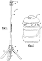
- a laser calibration apparatus 10 is illustrated in association with an exemplary laser tripod assembly 12.
- the laser calibration apparatus 10 and the associated method is used to calibrate a plurality of laser sources, as will be described in greater detail below, such that the laser tripod assembly 12 may be used to project a horizontal continuous laser line onto a given surface.
- the laser tripod assembly 12 generally includes a laser head 14 removably attached to an expandable neck 16 extending from a tripod base 18.
- the tripod base 18 includes a plurality of legs 20.
- a detailed description of this exemplary laser tripod assembly 12 may be found in commonly assigned co-pending application no. 10/979,953 .
- the laser head 14 includes a housing 22 used to protect the laser calibration apparatus 10 ( Figure 1 ) located therein.
- a plurality of windows 24 are formed in a top portion of the housing 22 to allow the laser sources located therein to emit laser beams from the laser head 14.
- the laser calibration apparatus 10 is illustrated in operative association with the laser head 14.
- the laser calibration apparatus 10 generally includes a pendulum 26, a laser deck 28 mounted to the pendulum 26 and a plurality of laser sources 30 mounted to the laser deck 28.
- the pendulum 26 includes a long shaft 32 extending between a pivot point 34 located at an end thereof and a weighted magnet 36, located at an opposite end of the shaft 32.
- the pivot point 34 is rotatably connected to a top portion 38 of the housing 22 in the laser head 14.
- the pivot point 34 allows the pendulum 26 to move in the X and Y directions (as indicated in Figure 4 ).
- the weighted magnet 36 acts to keep the shaft 32 perpendicular to a perfectly horizontal line.
- the weighted magnet 36 engages a metal contact 40 mounted to the housing 22.
- the metal contact 40 may be moved by engaging a switch (not shown) such that the end of the pendulum 26 with the weighted magnet 36 may move freely.
- the weighted magnet 36 engages the metal contact 40, thereby keeping the pendulum 26 from rotating about the pivot point 34.
- the metal contact 40 is used to keep the pendulum 26 from moving when the laser tripod assembly 12 is being transported, thereby preventing the laser calibration apparatus 10 from moving during transport.
- the laser deck 28 is mounted to the shaft 32 of the pendulum 26 near the pivot point 34.
- fewer or more than three laser sources 30 and three laser decks 28 may be employed with the present invention.
- Each laser source 30 has a calibration position that is defined by six degrees of movement including an X axis, a Y axis, a Z axis, rotation about the X axis (roll), rotation about the Y axis (pitch), and rotation about the Z axis (yaw).
- the laser deck 28 extends perpendicularly outward from the shaft 32.
- the laser deck 28 has a lower surface 42 with a groove 44 formed therein. As will be described in greater detail below, the groove 44 is used to allow a laser source 30 to pivot at that point, thereby adjusting pitch.
- the laser deck 28 further includes a top surface 46 located above the laser source 30.
- the top surface 46 extends the length of the laser source 30 and is mounted to the pendulum 26. There is a top surface 46 for every laser source 30.
- the top surface 46 includes a pitch screw 48 extending therethrough at one end of the top surface 46 and a biasing member 50 extending from the top surface 46 towards the laser source 30 at the opposite end of the top surface 46 from the pitch screw 48. As will described in greater detail below, the pitch screw 48 and the biasing member 50 act to adjust the pitch of the laser source 30.
- the laser source 30 includes a barrel holder 50, a laser barrel 52 and a lens holder 54.
- the barrel holder 50 includes an opening 56 sized to receive the laser barrel 52 therein.
- the opening 56 is formed on a front face 58 of the barrel holder 50.
- a slot 60 extends from the opening 56 onto a top surface 62 of the barrel holder 50.
- the slot 60 is sized to receive a portion 70 of the laser barrel 52, as will be described below.
- the barrel holder 50 also includes a rib 64 formed on a bottom surface 66 thereof. The rib 64 is sized to fit within the groove 44 ( Figure 4 ) of the laser deck 28.
- the laser barrel 52 houses a laser diode (not shown) that generates the laser beam used in the invention.
- a vertical fin 70 extends up from the laser barrel 52.
- the vertical fin 70 is sized to fit within the slot 60 of the barrel holder 50 when the laser barrel 52 is inserted into the opening 56.
- the laser barrel 52 further includes a pair of grooves 72 and a screw mount 74 formed on an end of the laser barrel 52 for receiving portions of the lens holder 54.
- Lens holder 54 includes a lens 76 mounted therein used to focus the laser beam generated from the laser diode (not shown) in the laser barrel 52.
- the lens holder 54 includes a pair of tabs 78 sized to fit within the groove 72 of the laser barrel 52. The tabs 78 secure the lens holder 54 onto the laser barrel 52.
- the laser source 30 includes two adjustment devices used to calibrate the laser source 30 including a roll screw 80 and a crown screw 82.
- the roll screw 80 fits within screw holes formed in the barrel holder 50 and the vertical fin 70 of the laser barrel 52. As will be described below, adjusting the roll screw 80 in turn moves the fin 70 thereby adjusting the laser barrel 52 relative to the barrel holder 50.
- the crown screw 82 fits within screw holes in the lens holder 54 and the screw mount 74 of the laser barrel 52. As will be described below, adjusting the crown screw 82 adjusts the crowning effect of the laser emitted through the lens 76 of the lens holder 54.
- one of the laser sources 30 is selected and activated such that a laser beam is being emitted from the selected laser source 30 onto an object thereby creating a laser line.
- the crown screw 82 of the selected laser source 30 is adjusted to eliminate any crowning in the laser line (e.g., removing any arc in the laser line such that it is straight). Adjustment of the crown screw 82 moves the lens holder 54 relative to the laser barrel 52 since the tabs 78 keep the lens holder 54 secured at a top of the lens holder 54.
- the roll screw 80 of the selected laser source 30 is used to adjust the laser line to a horizontal plane. Adjusting the roll screw 80 moves the vertical fin 70 and in turn the laser barrel 52 relative to the barrel holder 50. Once the selected laser source 30 has been adjusted using the crown screw 82 and the roll screw 80 to create a straight horizontal line, each of the other plurality of laser sources 30 are then similarly adjusted using the crown screw 82 and the roll screw 80. At this point the laser lines emitted from all of the laser sources 30 are straight and horizontal. However, each laser line may not be in alignment, or in the same plane, as the next.
- each of the laser lines emitted from the laser sources 30 are all on the same plane (e.g., each laser line is in alignment with one another) thereby forming a "laser plane".
- the laser plane should be straight and continuous, although not necessarily horizontal. Since the biasing members 50 bias an end of the laser sources 30 away from the top surfaces 46 of the laser decks 28, by adjusting the pitch screws 48 the laser sources 30 are forced to pivot about the ribs 64 and grooves 44 until such time that the laser sources 30 are planar with one another.
- the pendulum 26 In order to bring the laser plane to a horizontal plane, the pendulum 26 is allowed to swing freely such that the shaft 32 of the pendulum 26 is completely vertical.
- the laser lines of the laser sources 30 are straight and in alignment with one another in the laser plane.
- the laser plane may not be horizontal.
- Balance screws 84 located on an end of the shaft 32, are adjusted to bring the laser plane to a horizontal plane.
- the balance screws 84 adjust the center of gravity of the pendulum 26 by moving the center of mass of the balance screws 84 closer or farther away from the shaft 32.
- each of the plurality of laser sources 30 are brought into the same plane and then brought into the horizontal plane. At any point thereafter, the calibration method may be repeated in order to recalibrate the laser sources 30.
Landscapes
- Physics & Mathematics (AREA)
- Engineering & Computer Science (AREA)
- General Physics & Mathematics (AREA)
- Radar, Positioning & Navigation (AREA)
- Remote Sensing (AREA)
- Lasers (AREA)
- Mounting And Adjusting Of Optical Elements (AREA)
- Semiconductor Lasers (AREA)
Claims (1)
- Laserkalibrationsvorrichtung, umfassend :ein Gehäuse (22) ;ein Pendel (26), das schwenkbar an das Gehäuse (22) gekuppelt ist und daran herabhängt;ein Laserdeck (28), das am Pendel (26) angebracht ist;zumindest einen Laser (30) zum Aussenden einer Laserlinie, wobei der Laser schwenkbar am Laserdeck (28) angebracht ist und eine Lasertrommel, die innerhalb eines Trommelhalters (50) drehbar ist, und eine Laserlinse (76) aufweist;einen ersten Einstellmechanismus (48), der zwischen dem Laserdeck (28) und dem Laser (30) zum Schwenken des Lasers (30) bezüglich des Laserdecks (28) zum Einstellen einer Neigung der Laserlinie angebracht ist;einen vierten Einstellmechanismus (84), der am Pendel (26) zum Einstellen eines Schwerpunkts des Pendels (26) angebracht ist;dadurch gekennzeichnet, dass die Laserlinse (76) schwenkbar an die Lasertrommel (52) gekuppelt ist, wobei ferner ein zweiter Einstellmechanismus (80) vorgesehen ist, der zwischen dem Trommelhalter (50) und der Lasertrommel (52) zum Drehen der Lasertrommel (52) und der Laserlinse (76) bezüglich des Trommelhalters (50) zum Einstellen einer Rollbewegung der Laserlinie angebracht ist;einen dritten Einstellmechanismus (82), der zwischen der Lasertrommel (50) und der Laserlinse (76) zum Schwenken der Laserlinse (76) bezüglich der Lasertrommel (50) zum Einstellen einer Längsballigkeit der Laserlinie angebracht ist; undwobei der erste, zweite, dritte und vierte Einstellmechanismus zum Herstellen des horizontalen Verlaufs der Laserlinie, die vom Laser ausgesendet wird, benutzt werden.
Applications Claiming Priority (2)
| Application Number | Priority Date | Filing Date | Title |
|---|---|---|---|
| US54497704P | 2004-02-13 | 2004-02-13 | |
| US544977P | 2004-02-13 |
Publications (3)
| Publication Number | Publication Date |
|---|---|
| EP1564526A2 EP1564526A2 (de) | 2005-08-17 |
| EP1564526A3 EP1564526A3 (de) | 2011-07-06 |
| EP1564526B1 true EP1564526B1 (de) | 2016-12-21 |
Family
ID=34700226
Family Applications (1)
| Application Number | Title | Priority Date | Filing Date |
|---|---|---|---|
| EP05002686.3A Expired - Lifetime EP1564526B1 (de) | 2004-02-13 | 2005-02-09 | Laserkalibrationsvorrichtung |
Country Status (6)
| Country | Link |
|---|---|
| US (1) | US7111406B2 (de) |
| EP (1) | EP1564526B1 (de) |
| CN (1) | CN1661326B (de) |
| AU (1) | AU2005200542A1 (de) |
| NZ (1) | NZ538122A (de) |
| TW (1) | TW200530629A (de) |
Families Citing this family (20)
| Publication number | Priority date | Publication date | Assignee | Title |
|---|---|---|---|---|
| US7073269B2 (en) * | 2004-10-19 | 2006-07-11 | Trimble Navigation Limited | Self-leveling laser alignment tool and method thereof |
| GB2434448B (en) * | 2006-01-24 | 2010-06-16 | Durham John Anthony Douglas Br | Levelling device |
| CN101078623B (zh) * | 2006-05-26 | 2010-05-12 | 南京德朔实业有限公司 | 自水平激光标线装置及其控制方法 |
| US20120123736A1 (en) * | 2010-11-11 | 2012-05-17 | Holgate Michael S | System for rapid assessment of grade variations and method for using a system |
| CN103185736B (zh) * | 2012-01-03 | 2015-05-27 | 宏恒胜电子科技(淮安)有限公司 | 电路板孔内焊锡的测试方法 |
| US9277206B1 (en) * | 2013-01-28 | 2016-03-01 | Cognex Corporation | Dual-view laser-based three-dimensional capture system and method for employing the same |
| USD717185S1 (en) * | 2013-03-15 | 2014-11-11 | Trimble Navigation Limited | Survey system |
| TWI479123B (zh) * | 2014-01-14 | 2015-04-01 | Da Rong Lin | 雷射頭、雷射模組及十字雷射測量儀 |
| CN105444744B (zh) * | 2014-09-24 | 2019-06-18 | 鸿富锦精密工业(深圳)有限公司 | 校正装置及校正方法 |
| CN104713532B (zh) * | 2015-03-10 | 2017-01-18 | 浙江新蓝达实业股份有限公司 | 一种具有自校正功能的激光标线仪 |
| CN104713531B (zh) * | 2015-03-10 | 2017-01-25 | 武汉建工集团股份有限公司 | 一种带刻度自动安平激光水准仪可调支架 |
| USD767419S1 (en) * | 2015-03-19 | 2016-09-27 | Black & Decker Inc. | Laser tool |
| USD766757S1 (en) * | 2015-03-19 | 2016-09-20 | Black & Decker Inc. | Laser tool |
| EP3118577B1 (de) * | 2015-07-17 | 2019-06-26 | Leica Geosystems AG | Kalibrierungsvorrichtung und kalibrierungsverfahren für eine vorrichtung zum prüfen der horizontalen richtigkeit eines laserstrahls |
| US10006768B2 (en) | 2016-03-15 | 2018-06-26 | Stanley Black & Decker Inc. | Laser level |
| DE102017220467A1 (de) * | 2017-11-16 | 2019-05-16 | Robert Bosch Gmbh | Befestigungsvorrichtung zum Befestigen einer Lichtquelle an einem Kalibriertool |
| CN207515786U (zh) * | 2017-11-30 | 2018-06-19 | 浙江荣胜工具有限公司 | 自动安平激光标线指示装置 |
| CN111439351B (zh) * | 2020-03-26 | 2021-09-28 | 中船澄西船舶修造有限公司 | 一种柱塞式液压舵机安装检测装置 |
| CN114322961A (zh) * | 2022-01-10 | 2022-04-12 | 缪苗苗 | 一种桥梁用激光水准仪 |
| CN115032163A (zh) * | 2022-06-28 | 2022-09-09 | 南京康测自动化设备有限公司 | 一种高精度的激光器垂直度校准装置 |
Family Cites Families (18)
| Publication number | Priority date | Publication date | Assignee | Title |
|---|---|---|---|---|
| CH669037A5 (de) * | 1986-01-18 | 1989-02-15 | Hans Rudolf Ammann | Laserstrahl-nivelliergeraet. |
| DE4033630A1 (de) * | 1990-10-23 | 1992-04-30 | Busch Dieter & Co Prueftech | Erdlot zum bestimmen von senkrechten und waagrechten |
| CN2128391Y (zh) * | 1992-07-05 | 1993-03-17 | 中国科学技术大学 | 一种便携式电子散斑干涉仪光学头 |
| IT1275249B (it) * | 1995-02-22 | 1997-07-31 | Micro Italiana Spa | Dispositivo proiettore di uno o piu' fasci piani di raggi laser divergenti autolivellante a gravita' per la proiezione di una o piu' rette orizzontali e/o verticali su corpi del tipo parete o simili |
| US5539990A (en) * | 1995-05-30 | 1996-07-30 | Le; Mike | Three-dimensional optical levelling, plumbing and angle-calibrating instrument |
| US5836081A (en) * | 1996-05-29 | 1998-11-17 | Charles F. Schroeder | Light beam leveling means and method |
| US5782002A (en) * | 1996-06-03 | 1998-07-21 | Reed; Edwin D. | Laser guidance means |
| US6782034B2 (en) * | 1999-12-29 | 2004-08-24 | Chuying Li | Laser plumbing and leveling instrument which adjusting height of horizontal line |
| US6513251B2 (en) * | 2001-01-11 | 2003-02-04 | Quarton, Inc. | Illuminable laser sight |
| TW463943U (en) * | 2001-01-12 | 2001-11-11 | Wu Chi Ying | Full-angle automatic calibrated light emitting device |
| JP3522239B2 (ja) * | 2001-07-02 | 2004-04-26 | 株式会社オーディオテクニカ | 広角レーザーライン照射装置および方法 |
| CN2502234Y (zh) * | 2001-09-30 | 2002-07-24 | 常州市莱赛激光工程有限公司 | 自动安平激光标线装置 |
| US6625895B2 (en) * | 2001-12-04 | 2003-09-30 | Toolz, Ltd. | Servo-controlled automatic level and plumb tool |
| US6914930B2 (en) * | 2002-05-31 | 2005-07-05 | Black & Decker Inc. | Laser level |
| US6763595B1 (en) * | 2002-06-21 | 2004-07-20 | Pls - Pacific Laser Systems | Laser-based tool for indicating level, plumb and square |
| JP2004093504A (ja) * | 2002-09-03 | 2004-03-25 | Topcon Corp | 測量装置 |
| US6792685B1 (en) * | 2003-03-06 | 2004-09-21 | National University Of Singapore | Stabilized laser plumb |
| US6922901B1 (en) * | 2004-01-29 | 2005-08-02 | Chiu Yen Chou | Light leveling device having remote control |
-
2005
- 2005-02-04 TW TW094103742A patent/TW200530629A/zh unknown
- 2005-02-08 NZ NZ538122A patent/NZ538122A/en unknown
- 2005-02-08 AU AU2005200542A patent/AU2005200542A1/en not_active Abandoned
- 2005-02-08 CN CN200510062807.9A patent/CN1661326B/zh not_active Expired - Fee Related
- 2005-02-09 US US11/055,384 patent/US7111406B2/en not_active Expired - Lifetime
- 2005-02-09 EP EP05002686.3A patent/EP1564526B1/de not_active Expired - Lifetime
Non-Patent Citations (1)
| Title |
|---|
| None * |
Also Published As
| Publication number | Publication date |
|---|---|
| US20050193577A1 (en) | 2005-09-08 |
| CN1661326A (zh) | 2005-08-31 |
| TW200530629A (en) | 2005-09-16 |
| CN1661326B (zh) | 2010-10-13 |
| EP1564526A3 (de) | 2011-07-06 |
| NZ538122A (en) | 2006-10-27 |
| US7111406B2 (en) | 2006-09-26 |
| EP1564526A2 (de) | 2005-08-17 |
| AU2005200542A1 (en) | 2005-09-01 |
Similar Documents
| Publication | Publication Date | Title |
|---|---|---|
| US7111406B2 (en) | Laser calibration apparatus and method | |
| US7571546B1 (en) | Light line generating device | |
| US6754969B2 (en) | Self-leveling constructional laser | |
| US7121010B2 (en) | Line generating device | |
| US7523558B2 (en) | Tool incorporating a light line generating device | |
| US5864956A (en) | Level line and limb line combination | |
| US20060191147A1 (en) | Laser Level With Adjustable Laser Projection Line | |
| CN1537241A (zh) | 利用旋转头人工校平旋转激光器 | |
| CN1551975A (zh) | 激光线发生装置 | |
| JP2003194540A (ja) | ラインレーザ装置 | |
| US7513052B2 (en) | Light line generating device | |
| US6679609B2 (en) | Laser beam irradiation device | |
| US7377045B2 (en) | Laser reference device | |
| US20070124947A1 (en) | Light-plane projecting apparatus and lens | |
| JP2004301755A (ja) | ライン表示器 | |
| JP3148587B2 (ja) | 墨出し用レーザ装置 | |
| US20060064887A1 (en) | Universal laser beam generating device | |
| NZ548381A (en) | Laser calibration device | |
| JP4549181B2 (ja) | レーザー墨出し器 | |
| JP4628192B2 (ja) | レーザー墨出し器およびその三脚用傾き調整アタッチメント | |
| JP2509510Y2 (ja) | 平面設定器 | |
| CN201297572Y (zh) | 光线产生装置、光束产生装置和手工工具 | |
| WO2019194061A1 (ja) | 架台 | |
| JP3041840U (ja) | 墨出し装置 | |
| JP3099744U (ja) | 投影式墨出し装置 |
Legal Events
| Date | Code | Title | Description |
|---|---|---|---|
| PUAI | Public reference made under article 153(3) epc to a published international application that has entered the european phase |
Free format text: ORIGINAL CODE: 0009012 |
|
| AK | Designated contracting states |
Kind code of ref document: A2 Designated state(s): AT BE BG CH CY CZ DE DK EE ES FI FR GB GR HU IE IS IT LI LT LU MC NL PL PT RO SE SI SK TR |
|
| AX | Request for extension of the european patent |
Extension state: AL BA HR LV MK YU |
|
| PUAL | Search report despatched |
Free format text: ORIGINAL CODE: 0009013 |
|
| AK | Designated contracting states |
Kind code of ref document: A3 Designated state(s): AT BE BG CH CY CZ DE DK EE ES FI FR GB GR HU IE IS IT LI LT LU MC NL PL PT RO SE SI SK TR |
|
| AX | Request for extension of the european patent |
Extension state: AL BA HR LV MK YU |
|
| 17P | Request for examination filed |
Effective date: 20111205 |
|
| AKX | Designation fees paid |
Designated state(s): AT BE BG CH CY CZ DE DK EE ES FI FR GB GR HU IE IS IT LI LT LU MC NL PL PT RO SE SI SK TR |
|
| 17Q | First examination report despatched |
Effective date: 20131003 |
|
| GRAP | Despatch of communication of intention to grant a patent |
Free format text: ORIGINAL CODE: EPIDOSNIGR1 |
|
| INTG | Intention to grant announced |
Effective date: 20161013 |
|
| GRAS | Grant fee paid |
Free format text: ORIGINAL CODE: EPIDOSNIGR3 |
|
| STAA | Information on the status of an ep patent application or granted ep patent |
Free format text: STATUS: GRANT OF PATENT IS INTENDED |
|
| GRAA | (expected) grant |
Free format text: ORIGINAL CODE: 0009210 |
|
| STAA | Information on the status of an ep patent application or granted ep patent |
Free format text: STATUS: THE PATENT HAS BEEN GRANTED |
|
| AK | Designated contracting states |
Kind code of ref document: B1 Designated state(s): AT BE BG CH CY CZ DE DK EE ES FI FR GB GR HU IE IS IT LI LT LU MC NL PL PT RO SE SI SK TR |
|
| REG | Reference to a national code |
Ref country code: GB Ref legal event code: FG4D |
|
| REG | Reference to a national code |
Ref country code: CH Ref legal event code: EP |
|
| REG | Reference to a national code |
Ref country code: IE Ref legal event code: FG4D |
|
| REG | Reference to a national code |
Ref country code: AT Ref legal event code: REF Ref document number: 855871 Country of ref document: AT Kind code of ref document: T Effective date: 20170115 |
|
| REG | Reference to a national code |
Ref country code: DE Ref legal event code: R096 Ref document number: 602005050932 Country of ref document: DE |
|
| REG | Reference to a national code |
Ref country code: LT Ref legal event code: MG4D |
|
| REG | Reference to a national code |
Ref country code: NL Ref legal event code: MP Effective date: 20161221 |
|
| PG25 | Lapsed in a contracting state [announced via postgrant information from national office to epo] |
Ref country code: GR Free format text: LAPSE BECAUSE OF FAILURE TO SUBMIT A TRANSLATION OF THE DESCRIPTION OR TO PAY THE FEE WITHIN THE PRESCRIBED TIME-LIMIT Effective date: 20170322 Ref country code: SE Free format text: LAPSE BECAUSE OF FAILURE TO SUBMIT A TRANSLATION OF THE DESCRIPTION OR TO PAY THE FEE WITHIN THE PRESCRIBED TIME-LIMIT Effective date: 20161221 Ref country code: LT Free format text: LAPSE BECAUSE OF FAILURE TO SUBMIT A TRANSLATION OF THE DESCRIPTION OR TO PAY THE FEE WITHIN THE PRESCRIBED TIME-LIMIT Effective date: 20161221 |
|
| REG | Reference to a national code |
Ref country code: AT Ref legal event code: MK05 Ref document number: 855871 Country of ref document: AT Kind code of ref document: T Effective date: 20161221 |
|
| PG25 | Lapsed in a contracting state [announced via postgrant information from national office to epo] |
Ref country code: FI Free format text: LAPSE BECAUSE OF FAILURE TO SUBMIT A TRANSLATION OF THE DESCRIPTION OR TO PAY THE FEE WITHIN THE PRESCRIBED TIME-LIMIT Effective date: 20161221 Ref country code: BE Free format text: LAPSE BECAUSE OF NON-PAYMENT OF DUE FEES Effective date: 20170228 |
|
| PG25 | Lapsed in a contracting state [announced via postgrant information from national office to epo] |
Ref country code: NL Free format text: LAPSE BECAUSE OF FAILURE TO SUBMIT A TRANSLATION OF THE DESCRIPTION OR TO PAY THE FEE WITHIN THE PRESCRIBED TIME-LIMIT Effective date: 20161221 |
|
| PG25 | Lapsed in a contracting state [announced via postgrant information from national office to epo] |
Ref country code: CZ Free format text: LAPSE BECAUSE OF FAILURE TO SUBMIT A TRANSLATION OF THE DESCRIPTION OR TO PAY THE FEE WITHIN THE PRESCRIBED TIME-LIMIT Effective date: 20161221 Ref country code: IS Free format text: LAPSE BECAUSE OF FAILURE TO SUBMIT A TRANSLATION OF THE DESCRIPTION OR TO PAY THE FEE WITHIN THE PRESCRIBED TIME-LIMIT Effective date: 20170421 Ref country code: RO Free format text: LAPSE BECAUSE OF FAILURE TO SUBMIT A TRANSLATION OF THE DESCRIPTION OR TO PAY THE FEE WITHIN THE PRESCRIBED TIME-LIMIT Effective date: 20161221 Ref country code: EE Free format text: LAPSE BECAUSE OF FAILURE TO SUBMIT A TRANSLATION OF THE DESCRIPTION OR TO PAY THE FEE WITHIN THE PRESCRIBED TIME-LIMIT Effective date: 20161221 Ref country code: SK Free format text: LAPSE BECAUSE OF FAILURE TO SUBMIT A TRANSLATION OF THE DESCRIPTION OR TO PAY THE FEE WITHIN THE PRESCRIBED TIME-LIMIT Effective date: 20161221 |
|
| PG25 | Lapsed in a contracting state [announced via postgrant information from national office to epo] |
Ref country code: IT Free format text: LAPSE BECAUSE OF FAILURE TO SUBMIT A TRANSLATION OF THE DESCRIPTION OR TO PAY THE FEE WITHIN THE PRESCRIBED TIME-LIMIT Effective date: 20161221 Ref country code: ES Free format text: LAPSE BECAUSE OF FAILURE TO SUBMIT A TRANSLATION OF THE DESCRIPTION OR TO PAY THE FEE WITHIN THE PRESCRIBED TIME-LIMIT Effective date: 20161221 Ref country code: BE Free format text: LAPSE BECAUSE OF FAILURE TO SUBMIT A TRANSLATION OF THE DESCRIPTION OR TO PAY THE FEE WITHIN THE PRESCRIBED TIME-LIMIT Effective date: 20161221 Ref country code: BG Free format text: LAPSE BECAUSE OF FAILURE TO SUBMIT A TRANSLATION OF THE DESCRIPTION OR TO PAY THE FEE WITHIN THE PRESCRIBED TIME-LIMIT Effective date: 20170321 Ref country code: AT Free format text: LAPSE BECAUSE OF FAILURE TO SUBMIT A TRANSLATION OF THE DESCRIPTION OR TO PAY THE FEE WITHIN THE PRESCRIBED TIME-LIMIT Effective date: 20161221 Ref country code: PL Free format text: LAPSE BECAUSE OF FAILURE TO SUBMIT A TRANSLATION OF THE DESCRIPTION OR TO PAY THE FEE WITHIN THE PRESCRIBED TIME-LIMIT Effective date: 20161221 Ref country code: PT Free format text: LAPSE BECAUSE OF FAILURE TO SUBMIT A TRANSLATION OF THE DESCRIPTION OR TO PAY THE FEE WITHIN THE PRESCRIBED TIME-LIMIT Effective date: 20170421 |
|
| REG | Reference to a national code |
Ref country code: DE Ref legal event code: R097 Ref document number: 602005050932 Country of ref document: DE |
|
| PG25 | Lapsed in a contracting state [announced via postgrant information from national office to epo] |
Ref country code: MC Free format text: LAPSE BECAUSE OF FAILURE TO SUBMIT A TRANSLATION OF THE DESCRIPTION OR TO PAY THE FEE WITHIN THE PRESCRIBED TIME-LIMIT Effective date: 20161221 |
|
| REG | Reference to a national code |
Ref country code: CH Ref legal event code: PL |
|
| PLBE | No opposition filed within time limit |
Free format text: ORIGINAL CODE: 0009261 |
|
| STAA | Information on the status of an ep patent application or granted ep patent |
Free format text: STATUS: NO OPPOSITION FILED WITHIN TIME LIMIT |
|
| PG25 | Lapsed in a contracting state [announced via postgrant information from national office to epo] |
Ref country code: LI Free format text: LAPSE BECAUSE OF NON-PAYMENT OF DUE FEES Effective date: 20170228 Ref country code: CH Free format text: LAPSE BECAUSE OF NON-PAYMENT OF DUE FEES Effective date: 20170228 |
|
| 26N | No opposition filed |
Effective date: 20170922 |
|
| REG | Reference to a national code |
Ref country code: IE Ref legal event code: MM4A |
|
| PG25 | Lapsed in a contracting state [announced via postgrant information from national office to epo] |
Ref country code: DK Free format text: LAPSE BECAUSE OF FAILURE TO SUBMIT A TRANSLATION OF THE DESCRIPTION OR TO PAY THE FEE WITHIN THE PRESCRIBED TIME-LIMIT Effective date: 20161221 |
|
| REG | Reference to a national code |
Ref country code: FR Ref legal event code: ST Effective date: 20171031 |
|
| PG25 | Lapsed in a contracting state [announced via postgrant information from national office to epo] |
Ref country code: LU Free format text: LAPSE BECAUSE OF NON-PAYMENT OF DUE FEES Effective date: 20170209 |
|
| PG25 | Lapsed in a contracting state [announced via postgrant information from national office to epo] |
Ref country code: FR Free format text: LAPSE BECAUSE OF NON-PAYMENT OF DUE FEES Effective date: 20170228 |
|
| PG25 | Lapsed in a contracting state [announced via postgrant information from national office to epo] |
Ref country code: IE Free format text: LAPSE BECAUSE OF NON-PAYMENT OF DUE FEES Effective date: 20170209 Ref country code: SI Free format text: LAPSE BECAUSE OF FAILURE TO SUBMIT A TRANSLATION OF THE DESCRIPTION OR TO PAY THE FEE WITHIN THE PRESCRIBED TIME-LIMIT Effective date: 20161221 |
|
| PGFP | Annual fee paid to national office [announced via postgrant information from national office to epo] |
Ref country code: DE Payment date: 20180130 Year of fee payment: 14 Ref country code: GB Payment date: 20180207 Year of fee payment: 14 |
|
| PG25 | Lapsed in a contracting state [announced via postgrant information from national office to epo] |
Ref country code: HU Free format text: LAPSE BECAUSE OF FAILURE TO SUBMIT A TRANSLATION OF THE DESCRIPTION OR TO PAY THE FEE WITHIN THE PRESCRIBED TIME-LIMIT; INVALID AB INITIO Effective date: 20050209 |
|
| REG | Reference to a national code |
Ref country code: DE Ref legal event code: R119 Ref document number: 602005050932 Country of ref document: DE |
|
| GBPC | Gb: european patent ceased through non-payment of renewal fee |
Effective date: 20190209 |
|
| PG25 | Lapsed in a contracting state [announced via postgrant information from national office to epo] |
Ref country code: CY Free format text: LAPSE BECAUSE OF NON-PAYMENT OF DUE FEES Effective date: 20161221 |
|
| PG25 | Lapsed in a contracting state [announced via postgrant information from national office to epo] |
Ref country code: DE Free format text: LAPSE BECAUSE OF NON-PAYMENT OF DUE FEES Effective date: 20190903 Ref country code: GB Free format text: LAPSE BECAUSE OF NON-PAYMENT OF DUE FEES Effective date: 20190209 |
|
| PG25 | Lapsed in a contracting state [announced via postgrant information from national office to epo] |
Ref country code: TR Free format text: LAPSE BECAUSE OF FAILURE TO SUBMIT A TRANSLATION OF THE DESCRIPTION OR TO PAY THE FEE WITHIN THE PRESCRIBED TIME-LIMIT Effective date: 20161221 |