EP1564865A1 - Schenkelpolmaschine mit mindestens einer Polspule - Google Patents
Schenkelpolmaschine mit mindestens einer Polspule Download PDFInfo
- Publication number
- EP1564865A1 EP1564865A1 EP04003171A EP04003171A EP1564865A1 EP 1564865 A1 EP1564865 A1 EP 1564865A1 EP 04003171 A EP04003171 A EP 04003171A EP 04003171 A EP04003171 A EP 04003171A EP 1564865 A1 EP1564865 A1 EP 1564865A1
- Authority
- EP
- European Patent Office
- Prior art keywords
- pole
- spring
- coil
- salient
- machine according
- Prior art date
- Legal status (The legal status is an assumption and is not a legal conclusion. Google has not performed a legal analysis and makes no representation as to the accuracy of the status listed.)
- Withdrawn
Links
- 238000004804 winding Methods 0.000 title description 4
- 238000001816 cooling Methods 0.000 claims abstract description 26
- 238000009413 insulation Methods 0.000 claims description 2
- 239000002826 coolant Substances 0.000 description 7
- RYGMFSIKBFXOCR-UHFFFAOYSA-N Copper Chemical compound [Cu] RYGMFSIKBFXOCR-UHFFFAOYSA-N 0.000 description 2
- 229910052802 copper Inorganic materials 0.000 description 2
- 239000010949 copper Substances 0.000 description 2
- 210000002414 leg Anatomy 0.000 description 2
- 102100040287 GTP cyclohydrolase 1 feedback regulatory protein Human genes 0.000 description 1
- 101710185324 GTP cyclohydrolase 1 feedback regulatory protein Proteins 0.000 description 1
- 229910000639 Spring steel Inorganic materials 0.000 description 1
- 239000004020 conductor Substances 0.000 description 1
- 230000005284 excitation Effects 0.000 description 1
- 239000011152 fibreglass Substances 0.000 description 1
- 230000005484 gravity Effects 0.000 description 1
- 238000002955 isolation Methods 0.000 description 1
- 238000004519 manufacturing process Methods 0.000 description 1
- 210000000689 upper leg Anatomy 0.000 description 1
- 238000009423 ventilation Methods 0.000 description 1
Images
Classifications
-
- H—ELECTRICITY
- H02—GENERATION; CONVERSION OR DISTRIBUTION OF ELECTRIC POWER
- H02K—DYNAMO-ELECTRIC MACHINES
- H02K3/00—Details of windings
- H02K3/46—Fastening of windings on the stator or rotor structure
- H02K3/52—Fastening salient pole windings or connections thereto
- H02K3/527—Fastening salient pole windings or connections thereto applicable to rotors only
Definitions
- the invention relates to a salient pole with at least one in an axial direction of the Pole spool extending pole coil under a Pole shoe is arranged on a running body.
- EP 0 415 057 B1 an arrangement for the forced supply of a cooling medium in a gap between a pole core of the rotor body and the Pole coil known in the gap between pole core and Pole coil is provided a guide, which the Split divided into two spaces, which is essentially only on pole cap end of the gap in free connection and otherwise flows through one after the other.
- a guide which the Split divided into two spaces, which is essentially only on pole cap end of the gap in free connection and otherwise flows through one after the other.
- Such Guide device is relatively expensive produce and needs a suitably adapted, special assembly.
- the invention is based on the object Schenkelpolmaschine of the type mentioned in addition to improve that arranged on the rotor body pole coils be cooled better in a relatively inexpensive way.
- the object is according to the invention with a generic Schenkelpolmaschine solved in which the pole coil means at least one between the pole coil and the rotor body arranged spring urged against the pole piece and by that of the spring between the pole coil and the rotor body produced distance an axial cooling channel is created.
- the object is further achieved with a salient pole machine, in which the pole coil by means of at least one between the Pole coil and the rotor body arranged spring against the Polschuh is pushed, which is designed as a leaf spring.
- Schenkelpolmaschine is that between the pole coil and the Rotor body provided spring with at least one in Essentially formed U-shaped section and with a the two legs of this substantially U-shaped Section is the pole coil against the associated pole piece crowded.
- the space inside the U-shaped section serves then as a passage for forming the axial according to the invention Cooling channel.
- a spring with two is advantageous Essentially U-shaped, partially overlapping one another Provided sections that share essentially an O-shape form, which is open in one place.
- Such "annular" spring can with appropriate design in radial direction apply a high spring force and provides nevertheless in their interior a comparatively large one Through opening as a cooling channel available.
- the O-shaped spring should be at least a fastener at the opening of the O-shape attached to the runner body opposite side of the O-shape be. The spring is then securely held on the runner body, while their two are essentially semi-cylindrical Spring arms each one of two pole coils against the push the corresponding pole piece.
- the spring stiffness of the invention provided spring should be advantageously between about 1 and 4 N / mm, in particular between about 2 and 3 N / mm.
- Winding height tolerance of +/- 2mm can be compensated.
- two leaf springs can be inserted into each other or side by side.
- the area load between the spring and the pole coil or an insulation element arranged there should be within the limits of about 20 to 30 N / mm 2 .
- the spring is so is shaped that in the tensioned state of their investment point or Area at the associated pole coil or at one there arranged isolation element of the gravity axis of the Pole coil is slightly removed.
- the distance between Focus axis and investment point should especially between 2 and 5 mm, most preferably 3.5 mm.
- the spring is advantageous in particular a greater travel and a flatter course of Spring force.
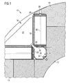
- a substantially cylindrical one Femoral pole rotor 10 of a salient pole generator shown a runner body 12 and on the outside thereof arranged elongated pole pieces 14 has. Between each two elongated pole pieces 14 is a substantially in Cross-section triangular recess 16 formed in Shape of a groove also over the entire length of Runner body 12 extends.
- Pole coil 18 In a single recess 16 are each two in the axial direction of the salient pole runner 10 extending Pole coil 18 is arranged, each in an insulating frame 20th are embedded.
- the pole coils 18 are each at the Leg sides of the cross-sectionally triangular recess 16 on the rotor body 12 and are at their radially outer Enveloped end areas of each pole piece 14. Between the two pole coils 18 is also in the Cross section substantially triangular coil support 22 arranged by means of the pole coils in the recess 16th are restrained.
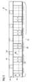
- Cooling medium particularly effective on the pole coils 18th can absorb the resulting heat energy, are the pole coils 18 each of a plurality of radial cooling channels 36th interspersed, in the axial direction in particular between two leaf springs 24 are formed in the pole coils 18 are.
- the radial cooling channels 36 extend starting from the axial cooling passage 34 through the insulating frame 20 and the associated pole coil 18. They lead to associated Air outlet openings 38, the coordinated pole pieces 14th pass through and to the outside of the femoral pole runner 10 to lead. Through the radial cooling channels can in this way the cooling medium supplied through the axial cooling channels 34 be discharged through the pole coils 18 therethrough.
Landscapes
- Engineering & Computer Science (AREA)
- Power Engineering (AREA)
- Motor Or Generator Cooling System (AREA)
- Iron Core Of Rotating Electric Machines (AREA)
- Windings For Motors And Generators (AREA)
- Insulation, Fastening Of Motor, Generator Windings (AREA)
- Synchronous Machinery (AREA)
Priority Applications (9)
| Application Number | Priority Date | Filing Date | Title |
|---|---|---|---|
| EP04003171A EP1564865A1 (de) | 2004-02-12 | 2004-02-12 | Schenkelpolmaschine mit mindestens einer Polspule |
| ES05707129T ES2372695T3 (es) | 2004-02-12 | 2005-02-01 | Máquina de polos salientes con al menos una bobina inductora. |
| AT05707129T ATE527741T1 (de) | 2004-02-12 | 2005-02-01 | Schenkelpolmaschine mit mindestens einer polspule |
| JP2006552504A JP2007522787A (ja) | 2004-02-12 | 2005-02-01 | 界磁コイルを有する突極電機 |
| US10/589,176 US7915771B2 (en) | 2004-02-12 | 2005-02-01 | Salient-pole machine comprising at least one field coil |
| PCT/EP2005/000994 WO2005078898A1 (de) | 2004-02-12 | 2005-02-01 | Schenkelpolmaschine mit mindestens einer polspule |
| PL05707129T PL1721379T3 (pl) | 2004-02-12 | 2005-02-01 | Maszyna jawnobiegunowa z co najmniej jedną cewką biegunową |
| EP05707129A EP1721379B1 (de) | 2004-02-12 | 2005-02-01 | Schenkelpolmaschine mit mindestens einer polspule |
| CN200580012313A CN100588080C (zh) | 2004-02-12 | 2005-02-01 | 具有至少一个极线圈的凸极电机 |
Applications Claiming Priority (1)
| Application Number | Priority Date | Filing Date | Title |
|---|---|---|---|
| EP04003171A EP1564865A1 (de) | 2004-02-12 | 2004-02-12 | Schenkelpolmaschine mit mindestens einer Polspule |
Publications (1)
| Publication Number | Publication Date |
|---|---|
| EP1564865A1 true EP1564865A1 (de) | 2005-08-17 |
Family
ID=34684678
Family Applications (2)
| Application Number | Title | Priority Date | Filing Date |
|---|---|---|---|
| EP04003171A Withdrawn EP1564865A1 (de) | 2004-02-12 | 2004-02-12 | Schenkelpolmaschine mit mindestens einer Polspule |
| EP05707129A Expired - Lifetime EP1721379B1 (de) | 2004-02-12 | 2005-02-01 | Schenkelpolmaschine mit mindestens einer polspule |
Family Applications After (1)
| Application Number | Title | Priority Date | Filing Date |
|---|---|---|---|
| EP05707129A Expired - Lifetime EP1721379B1 (de) | 2004-02-12 | 2005-02-01 | Schenkelpolmaschine mit mindestens einer polspule |
Country Status (8)
| Country | Link |
|---|---|
| US (1) | US7915771B2 (pl) |
| EP (2) | EP1564865A1 (pl) |
| JP (1) | JP2007522787A (pl) |
| CN (1) | CN100588080C (pl) |
| AT (1) | ATE527741T1 (pl) |
| ES (1) | ES2372695T3 (pl) |
| PL (1) | PL1721379T3 (pl) |
| WO (1) | WO2005078898A1 (pl) |
Families Citing this family (8)
| Publication number | Priority date | Publication date | Assignee | Title |
|---|---|---|---|---|
| GB0915872D0 (en) * | 2009-09-10 | 2009-10-14 | Goodrich Control Sys | Rotor assembly |
| DE102011006681A1 (de) * | 2011-04-01 | 2012-10-04 | Aloys Wobben | Polschuh |
| KR101566086B1 (ko) | 2013-11-05 | 2015-11-04 | 현대중공업 주식회사 | 코일서포터 및 이를 포함하는 돌극형 회전자 |
| EP2876783A1 (de) * | 2013-11-25 | 2015-05-27 | Siemens Aktiengesellschaft | Schenkelpolläufer |
| JP6907609B2 (ja) * | 2017-03-09 | 2021-07-21 | 株式会社明電舎 | 回転電機 |
| DE102021115642A1 (de) | 2021-06-17 | 2022-12-22 | Bayerische Motoren Werke Aktiengesellschaft | Mehrteiliger Rotor für eine elektrische Maschine, elektrische Maschine sowie Kraftfahrzeug |
| CN113629920A (zh) * | 2021-09-06 | 2021-11-09 | 上海电气集团上海电机厂有限公司 | 一种大型凸极同步电机励磁绕组冷却结构 |
| CN119519293B (zh) * | 2024-10-31 | 2025-06-13 | 杭州新恒力电机制造有限公司 | 中大型同步电动机转子磁极安装定位辅助装置 |
Citations (6)
| Publication number | Priority date | Publication date | Assignee | Title |
|---|---|---|---|---|
| FR2180658A1 (pl) * | 1972-04-20 | 1973-11-30 | Elektromaschinenbau Veb K | |
| EP0008250A1 (fr) * | 1978-08-11 | 1980-02-20 | C E M COMPAGNIE ELECTRO MECANIQUE Société Anonyme | Rotor de machine électrique à pôles saillants |
| EP0052383A1 (de) * | 1980-11-17 | 1982-05-26 | BBC Aktiengesellschaft Brown, Boveri & Cie. | Kühlmediumsverteilkörper |
| JPS59169348A (ja) * | 1983-03-17 | 1984-09-25 | Toshiba Corp | 突極形回転子 |
| JPH02299438A (ja) * | 1989-05-11 | 1990-12-11 | Toshiba Corp | 突極形回転電機の回転子 |
| JPH03143239A (ja) * | 1989-10-26 | 1991-06-18 | Toshiba Corp | 突極形回転電機 |
Family Cites Families (7)
| Publication number | Priority date | Publication date | Assignee | Title |
|---|---|---|---|---|
| ATE97269T1 (de) | 1989-08-29 | 1993-11-15 | Asea Brown Boveri | Anordnung zur fuehrung des kuehlmediums in schenkelpolmaschinen. |
| CN1242882A (zh) * | 1996-11-07 | 2000-01-26 | 西门子西屋电力公司 | 定子端部线圈夹紧装置的预加载系统 |
| JPH1169681A (ja) * | 1997-08-06 | 1999-03-09 | Toshiba Corp | 突極形回転電機の回転子 |
| DE19810628A1 (de) | 1998-03-12 | 1999-09-16 | Heinz Dieter Eberhardt | Belüftungssystem für die Erregerwicklung großer Schenkelpolmaschinen |
| DE19839987C2 (de) * | 1998-09-02 | 2000-07-06 | Siemens Ag | Direktgekühlte Magnetspule, insbesondere Gradientenspule, sowie Verfahren zur Herstellung von Leitern dazu |
| JP2002058188A (ja) * | 2000-08-10 | 2002-02-22 | Mitsubishi Electric Corp | 突極形回転子 |
| CN100519300C (zh) * | 2003-02-20 | 2009-07-29 | 日本精工株式会社 | 电动动力转向装置 |
-
2004
- 2004-02-12 EP EP04003171A patent/EP1564865A1/de not_active Withdrawn
-
2005
- 2005-02-01 CN CN200580012313A patent/CN100588080C/zh not_active Expired - Lifetime
- 2005-02-01 WO PCT/EP2005/000994 patent/WO2005078898A1/de not_active Ceased
- 2005-02-01 JP JP2006552504A patent/JP2007522787A/ja active Pending
- 2005-02-01 ES ES05707129T patent/ES2372695T3/es not_active Expired - Lifetime
- 2005-02-01 AT AT05707129T patent/ATE527741T1/de active
- 2005-02-01 EP EP05707129A patent/EP1721379B1/de not_active Expired - Lifetime
- 2005-02-01 PL PL05707129T patent/PL1721379T3/pl unknown
- 2005-02-01 US US10/589,176 patent/US7915771B2/en active Active
Patent Citations (6)
| Publication number | Priority date | Publication date | Assignee | Title |
|---|---|---|---|---|
| FR2180658A1 (pl) * | 1972-04-20 | 1973-11-30 | Elektromaschinenbau Veb K | |
| EP0008250A1 (fr) * | 1978-08-11 | 1980-02-20 | C E M COMPAGNIE ELECTRO MECANIQUE Société Anonyme | Rotor de machine électrique à pôles saillants |
| EP0052383A1 (de) * | 1980-11-17 | 1982-05-26 | BBC Aktiengesellschaft Brown, Boveri & Cie. | Kühlmediumsverteilkörper |
| JPS59169348A (ja) * | 1983-03-17 | 1984-09-25 | Toshiba Corp | 突極形回転子 |
| JPH02299438A (ja) * | 1989-05-11 | 1990-12-11 | Toshiba Corp | 突極形回転電機の回転子 |
| JPH03143239A (ja) * | 1989-10-26 | 1991-06-18 | Toshiba Corp | 突極形回転電機 |
Non-Patent Citations (3)
| Title |
|---|
| PATENT ABSTRACTS OF JAPAN vol. 009, no. 023 (E - 293) 30 January 1985 (1985-01-30) * |
| PATENT ABSTRACTS OF JAPAN vol. 015, no. 082 (E - 1038) 26 February 1991 (1991-02-26) * |
| PATENT ABSTRACTS OF JAPAN vol. 015, no. 365 (E - 1111) 13 September 1991 (1991-09-13) * |
Also Published As
| Publication number | Publication date |
|---|---|
| CN1947322A (zh) | 2007-04-11 |
| WO2005078898A1 (de) | 2005-08-25 |
| ATE527741T1 (de) | 2011-10-15 |
| US7915771B2 (en) | 2011-03-29 |
| EP1721379B1 (de) | 2011-10-05 |
| EP1721379A1 (de) | 2006-11-15 |
| CN100588080C (zh) | 2010-02-03 |
| PL1721379T3 (pl) | 2012-03-30 |
| US20070278888A1 (en) | 2007-12-06 |
| ES2372695T3 (es) | 2012-01-25 |
| JP2007522787A (ja) | 2007-08-09 |
Similar Documents
| Publication | Publication Date | Title |
|---|---|---|
| EP2936655B1 (de) | Stator gepresst mit wickelkopfsupport | |
| EP2569853B1 (de) | Rotor für eine dynamoelektrische maschine | |
| DE102008005376A1 (de) | Lagerkäfig | |
| DE102020101149A1 (de) | Axialflussmaschine mit mechanisch fixierten Statorkernen mit radial verlaufenden Blechsegmenten | |
| EP2339202B1 (de) | Dämpfungs- und Federanordnung und Verfahren zu ihrer Herstellung | |
| DE102012110147A1 (de) | Rotor für einen Asynchronmotor in gebauter Ausführung | |
| EP2936656B1 (de) | Rotorpaket mit funktionsträger | |
| EP1721379B1 (de) | Schenkelpolmaschine mit mindestens einer polspule | |
| DE102016212382A1 (de) | Verfahren und Adapter zum Wickeln eines Spulenkorbs | |
| DE102016119352A1 (de) | Transportanker | |
| WO2009003659A2 (de) | Bremsscheibe mit kühlrippen | |
| DE102011121986B3 (de) | Korbspule für Draht, insbesondere für Schweißdraht | |
| EP3484024A1 (de) | Aktuator | |
| DE102021204200A1 (de) | Hohle Innenwelle für einen Rotor einer elektrischen Maschine | |
| DE60029718T2 (de) | Anker und Ankerblechzusammenbau für eine elektrische Maschine, insbesondere für einen Gleichstrommotor mit einem Kommutator | |
| DE102011054046A1 (de) | Spulendistanzblock einer dynamoelektrischen Maschine mit einer Strömungsablenkstruktur auf seiner spulenseitigen Oberfläche | |
| DE3031273A1 (de) | Elektromagnetische vorrichtung. | |
| DE1958501A1 (de) | Hochleistungsmotor | |
| DE102012021114B4 (de) | Elektrischer Generator für die Stromgewinnung in Kraftwerken | |
| DE102009027661A1 (de) | Stator in einem Elektromotor | |
| DE202020102064U1 (de) | Spannbare elektrische Heizvorrichtung | |
| DE102016102159A1 (de) | Drosselelement für einen Motorblock einer Verbrennungskraftmaschine, Motorblock für eine Verbrennungskraftmaschine, Verfahren zur Herstellung eines Motorblocks für eine Verbrennungskraftmaschine und Verbrennungskraftmaschine | |
| DE2138968C3 (de) | Drosselspule | |
| DE102023113747A1 (de) | Stator mit einem Abstützsteg zwischen Statorzahn und zugehöriger Wicklung und Axialflussmaschine | |
| WO1999046846A1 (de) | Belüftungssystem für die erregerwicklung grosser schenkelpolmaschinen |
Legal Events
| Date | Code | Title | Description |
|---|---|---|---|
| PUAI | Public reference made under article 153(3) epc to a published international application that has entered the european phase |
Free format text: ORIGINAL CODE: 0009012 |
|
| AK | Designated contracting states |
Kind code of ref document: A1 Designated state(s): AT BE BG CH CY CZ DE DK EE ES FI FR GB GR HU IE IT LI LU MC NL PT RO SE SI SK TR |
|
| AX | Request for extension of the european patent |
Extension state: AL LT LV MK |
|
| AKX | Designation fees paid | ||
| STAA | Information on the status of an ep patent application or granted ep patent |
Free format text: STATUS: THE APPLICATION IS DEEMED TO BE WITHDRAWN |
|
| 18D | Application deemed to be withdrawn |
Effective date: 20060217 |
|
| REG | Reference to a national code |
Ref country code: DE Ref legal event code: 8566 |