EP1566194A2 - Seringue, en particulier pour usages médicaux - Google Patents
Seringue, en particulier pour usages médicaux Download PDFInfo
- Publication number
- EP1566194A2 EP1566194A2 EP05001546A EP05001546A EP1566194A2 EP 1566194 A2 EP1566194 A2 EP 1566194A2 EP 05001546 A EP05001546 A EP 05001546A EP 05001546 A EP05001546 A EP 05001546A EP 1566194 A2 EP1566194 A2 EP 1566194A2
- Authority
- EP
- European Patent Office
- Prior art keywords
- syringe
- syringe barrel
- proximal end
- finger rest
- hooks
- Prior art date
- Legal status (The legal status is an assumption and is not a legal conclusion. Google has not performed a legal analysis and makes no representation as to the accuracy of the status listed.)
- Granted
Links
- 230000008901 benefit Effects 0.000 description 7
- 239000003814 drug Substances 0.000 description 7
- 229940079593 drug Drugs 0.000 description 7
- 238000004519 manufacturing process Methods 0.000 description 3
- 239000000243 solution Substances 0.000 description 3
- 239000011521 glass Substances 0.000 description 2
- 238000009434 installation Methods 0.000 description 2
- 238000004026 adhesive bonding Methods 0.000 description 1
- 239000011324 bead Substances 0.000 description 1
- 239000003560 cancer drug Substances 0.000 description 1
- 239000013013 elastic material Substances 0.000 description 1
- 230000036512 infertility Effects 0.000 description 1
- 238000001746 injection moulding Methods 0.000 description 1
- 230000002427 irreversible effect Effects 0.000 description 1
- 239000000463 material Substances 0.000 description 1
- 230000000284 resting effect Effects 0.000 description 1
- 238000007789 sealing Methods 0.000 description 1
- 231100000331 toxic Toxicity 0.000 description 1
- 230000002588 toxic effect Effects 0.000 description 1
- 238000003466 welding Methods 0.000 description 1
Images


Classifications
-
- A—HUMAN NECESSITIES
- A61—MEDICAL OR VETERINARY SCIENCE; HYGIENE
- A61M—DEVICES FOR INTRODUCING MEDIA INTO, OR ONTO, THE BODY; DEVICES FOR TRANSDUCING BODY MEDIA OR FOR TAKING MEDIA FROM THE BODY; DEVICES FOR PRODUCING OR ENDING SLEEP OR STUPOR
- A61M5/00—Devices for bringing media into the body in a subcutaneous, intra-vascular or intramuscular way; Accessories therefor, e.g. filling or cleaning devices, arm-rests
- A61M5/178—Syringes
- A61M5/31—Details
- A61M5/315—Pistons; Piston-rods; Guiding, blocking or restricting the movement of the rod or piston; Appliances on the rod for facilitating dosing ; Dosing mechanisms
- A61M5/31501—Means for blocking or restricting the movement of the rod or piston
-
- A—HUMAN NECESSITIES
- A61—MEDICAL OR VETERINARY SCIENCE; HYGIENE
- A61M—DEVICES FOR INTRODUCING MEDIA INTO, OR ONTO, THE BODY; DEVICES FOR TRANSDUCING BODY MEDIA OR FOR TAKING MEDIA FROM THE BODY; DEVICES FOR PRODUCING OR ENDING SLEEP OR STUPOR
- A61M5/00—Devices for bringing media into the body in a subcutaneous, intra-vascular or intramuscular way; Accessories therefor, e.g. filling or cleaning devices, arm-rests
- A61M5/178—Syringes
- A61M5/31—Details
- A61M5/3129—Syringe barrels
- A61M5/3137—Specially designed finger grip means, e.g. for easy manipulation of the syringe rod
- A61M2005/3139—Finger grips not integrally formed with the syringe barrel, e.g. using adapter with finger grips
-
- A—HUMAN NECESSITIES
- A61—MEDICAL OR VETERINARY SCIENCE; HYGIENE
- A61M—DEVICES FOR INTRODUCING MEDIA INTO, OR ONTO, THE BODY; DEVICES FOR TRANSDUCING BODY MEDIA OR FOR TAKING MEDIA FROM THE BODY; DEVICES FOR PRODUCING OR ENDING SLEEP OR STUPOR
- A61M5/00—Devices for bringing media into the body in a subcutaneous, intra-vascular or intramuscular way; Accessories therefor, e.g. filling or cleaning devices, arm-rests
- A61M5/178—Syringes
- A61M5/31—Details
- A61M5/315—Pistons; Piston-rods; Guiding, blocking or restricting the movement of the rod or piston; Appliances on the rod for facilitating dosing ; Dosing mechanisms
- A61M5/31501—Means for blocking or restricting the movement of the rod or piston
- A61M5/31505—Integral with the syringe barrel, i.e. connected to the barrel so as to make up a single complete piece or unit
Definitions
- the present invention relates to a syringe, in particular for medical applications, with a syringe barrel, the has a proximal and a distal end, with an in Syringe cylinder arranged piston plugs, and with a Back stop, which prevents the piston plug against unintentional Pulling out of the syringe barrel secures, with the back stop has at least two claw-like fishing hooks, the outside the syringe barrel at staggered circumferential positions are arranged.
- the invention further relates to a backgauge for such Syringe, with a fastener for attaching the Back stop at the proximal end of a syringe barrel and with at least two claw-like catch hooks outside the Syringe cylinder at staggered circumferential positions are arranged.
- a backgauge partially also Backstop or piston brake called
- WO 94/13339 shows a backgauge in which a claw-like catch hook into the inside of the syringe barrel protrudes and there in a sawtooth edge of the Engages piston rod.
- the fishing hook works in conjunction with the saw teeth on the piston rod like a pawl, the prevents retraction of the piston plug.
- a syringe is known in which a plate-shaped Finger rest on the proximal end of the syringe barrel is plugged.
- the finger rest has one sleeve-like extension, the perfect fit in the syringe barrel is inserted and there with a bead at the proximal end of the Syringe cylinder locked.
- the sleeve-like extension forms a back stop for the plunger stopper as it clears the Inner diameter of the syringe barrel narrowed at the proximal end.
- the above object is achieved by a syringe or a backgauge solved the type mentioned, wherein the fishing hook are arranged on a plate-shaped finger rest, the sitting proximal end of the syringe barrel or trained is to be located there.
- the new backstop follows the known approach, a unintentional removal of the piston plug by means of claw-like To prevent catching hooks.
- Arrangement are the catch hooks here, however, on a plate-shaped Finger rest arranged. This makes it possible for the new backgauge to use even with conventional syringes.
- a special design of the proximal syringe flange is not absolutely necessary, as on hand preferred embodiments will be shown below.
- the new backstop allows the easy removal of the piston plug, if desired is by just bent or separated one of the fishing hooks must become. Because such a manipulation on the other hand visible marks, the piston plug can not later introduced again unnoticed in the syringe barrel become. This is especially true when the total backslash irreversibly attached to the syringe barrel as shown in FIG a preferred embodiment is provided. In contrast this is the deliberate withdrawal in the known backlashes the piston plug either not possible, or she is possible in a way that has no visible traces leaves behind, so there is a risk that deliberate manipulation stay unrecognized at the syringe. A simple and protected against unrecognized manipulation access to the Piston plugs offer none of the known backlashes.
- the fishing hooks are free arranged accessible to the finger rest.
- Freely accessible in this context means that the fishing hooks for the operator of the syringe are readily apparent and the operator can reach at least one of the catch hooks in this way may he be able to bend or break this.
- This embodiment is therefore particularly suitable to the aforementioned To achieve advantages.
- the fishing hooks with their free ends inclined to the distal end of the syringe barrel.
- the finger rest is a separate one Component at the proximal end of the syringe barrel is attached.
- the Finger rest with the catch hook in one piece at the proximal end the syringe barrel is formed.
- has the preferred embodiment has the advantage that the new backgauge optional and especially in conventional syringe barrels can be used with round flange.
- Another The advantage is that the new backgauge of this Embodiment readily made of a different material can be as the syringe barrel. This can in particular a plastic backgauge, the high holding forces can be used on glass syringe barrels.
- the finger rest with a cylindrical shell-shaped wall connected to the syringe barrel encompasses the proximal end with a precise fit.
- the cylindrical shell-shaped wall (thus a sleeve-like extension) allows a very stable attachment of the new back stop on conventional syringe barrels. This is this Embodiment for the solution of the above task especially well suited.
- the wall has a lateral Opening on, the lateral sliding on the syringe barrel allows.
- the new backgauge can be special easily and rationally integrated into existing production processes become.
- the use of the new backgauge on conventional Syringe cylinders is thereby further facilitated.
- the finger rest is at the proximal End of the syringe barrel undetachably attached.
- This embodiment improves the protection against manipulation and makes it particularly advantageous use of the already discussed above options.
- the use of a Snap rings in the manner described allows one particularly rational and cost-effective installation.
- the fishing hooks are in one piece connected with the finger rest.
- the manufacturing costs Minimize the new syringe or the new back stop.
- the Fishing hook and the finger rest in a single injection molding step manufacture.
- the associated reduction of Number of parts also allows easy installation of the syringe.
- the free ends of the ends Fanghook above a final level, from the proximal End of the syringe barrel is defined.
- This embodiment has the advantage that the clear interior the syringe barrel by the new backgauge not is reduced. If desired, this represents the entire interior the syringe barrel for receiving the drug for Available. In addition, this embodiment facilitates a deliberate manipulation on the fishing hook.
- the free ends of the ends Fishing hooks on or outside a circular line that light Inner diameter of the syringe barrel corresponds.
- This embodiment also contributes to a removal of the Piston stopper is effectively prevented, without the internal volume to reduce the syringe barrel. Even if the free ends of the fishing hook outside of said circle is an effective safeguard against the removal of the Piston plug given as the plunger plug in the syringe barrel As a rule, are compressed to a good seal to reach on the inner walls of the syringe barrel. As soon as the piston stopper leaves the syringe barrel, it expands he is out and thus comes into contact with the fishing hooks.
- This preferred embodiment has the advantage that the Piston rod does not touch the catch hook when the syringe is actuated is present, i. the syringe can be unaffected by the back stop be operated. This allows a finer Reach dosage.
- Fig. 1 is an embodiment of the new syringe in its entirety designated by the reference numeral 10.
- the syringe 10 has a syringe barrel in a conventional manner 12 and a piston rod 13 at the proximal end 14 of the syringe barrel 12 is inserted.
- the distal end 16 of the syringe barrel 12 has a terminals, for example a luer-lock connector, not to attach one here shown needle.
- Reference numeral 18 is an embodiment of the new backgauge designated.
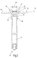
- the backgauge 18 serves a unintentional removal of the piston plug 20 (see FIG. 3, FIG. Fig. 4) from the syringe barrel 12 to prevent.
- the back stop 18 forms a proximal Closure element that allows the syringe 10 in the pre-filled Condition to end users to deliver.
- the distal end 16 in this case also with a closure element is sealed, for example, with a so mentioned tip-cap or a needle with needle cap.
- the backgauge 18 has in the illustrated embodiment a cylindrical shell-shaped wall 28 which is the proximal end of the Syringe cylinder 12 fits snugly around.
- the wall 28 has one Opening portion 30, which allows the back stop 18 laterally on the proximal end 14 of the syringe barrel 12th postpone.
- the back stop 18 has a finger rest 31 with two plate-shaped areas 32, 34, resting on two opposite sides of the syringe barrel 12 transverse to the Wall 28 extend.
- the plate areas 32, 34 close flush with the proximal end of the syringe barrel 12 from.
- Words embrace the two plate portions 32, 34 the proximal end flange 35 of the syringe barrel 12 flush, while the cylindrical shell-shaped wall 28 below the proximal End flange 35 abuts the syringe barrel 12.
- the plate areas 32, 34 each have a claw-like catch hook 36, 38 arranged.
- the backgauge 18 could basically consist of several joined parts.
- the catch hooks 36, 38 are each approximately L-shaped, a short leg of the L being perpendicular to the respective one Plate area 32, 34 stands up, while a longer one Leg with a slope to the distal end 16 of the syringe barrel 12 points radially inward.
- the free ends of the Fishing hooks 36, 38 thus point radially toward one another. They are located in the present embodiment exactly on or slightly outside a circle 39 whose diameter the clear inner diameter d of the syringe barrel 12 corresponds. In other embodiments, the free Ends the fishing hooks 36, 38 but also in the projected Protrude circle 39.
- the free ends of the fishing hooks 36, 38 are in this embodiment above a termination level 41, defined by the proximal end 14 of the syringe barrel 12 becomes. Notwithstanding this, however, it is also possible in principle that the free ends of the fishing hooks 36, 38 below the End level 41 and thus protrude into the syringe barrel 12.
- the reference numeral 43 denotes an edge piece, the one-piece with the finger rest 31 of the back stop 18 is formed.
- the edge piece 43 is located on the outer circumference of the syringe barrel 12 approximately midway between the two catch hooks 36, 38. Its dimensions are chosen that it is on the proximal end flange 35 of the syringe barrel 12 rests without falling in the clear inside diameter of Inject syringe barrel 12.
- the edge piece 43 secures the back stop 18 so against slipping to the distal End 16 of the syringe barrel 12.
- the reference numeral 44 in Fig. 1 denotes a ring which in a groove 50 which at the lower (distal) end of Wall 28 is formed.
- the ring 44 prevents lateral Pulling the back stop 18 from the syringe barrel 12, so that deliberate manipulation prevented or at least recognizable are made.
- the ring 44 Part of a tamper-evident closure, which in his Entity Subject of a parallel application of the present Applicant is.
- the Ring 44 in principle, however, also omitted, or the backgauge 18 is used in other ways, for example by gluing,shrinking or welding irreversible on the syringe barrel 12 attached.
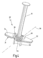
- Fig. 4 illustrates the basic operation of the backgauge 18.
- the free ends of the fishing hooks 36, 38 can rotate about an axis 56 due to the described arrangement, the sake of clarity, only for the fishing hook 36th is shown.
- the axis 56 is above the level 41 and outside the inside diameter d of the syringe barrel 12. If the piston plug 20 is pulled out of the syringe cylinder 12, he gets between the two free ends of the fishing hooks 36, 38 and gets there to the plant. Another pulling out the piston plug 20 causes the free ends perform a rotational movement about the corresponding axis 56. The clear distance between the two ends is reduced, the piston plug 20 so clamped tighter. A complete Removal of the piston plug 20 is due to the geometric Dimensions of the fishing hooks 36, 38 without destroying the fishing hooks not possible.
- the Back stop 18 with the finger rest 31 and the catch hook 36, 38 designed to work on conventional syringe barrels 12 can be placed with round flange.
- the backstop 18 it is also possible to form the backstop 18 so that it can be used in syringe barrels that have a own other flange.
- the basic principle of the present backgauge 18 to apply to syringe barrels that are already on their own have a finger rest 31.
- corresponding catch hooks 36, 38 above the finger rest 31st be arranged, either in one piece or by a supplementary Mounting member.
- the invention is not limited to exemplary embodiments limited with two hooks. There can also be three or used more radially facing each other Fanghaken become.
Landscapes
- Health & Medical Sciences (AREA)
- Vascular Medicine (AREA)
- Engineering & Computer Science (AREA)
- Anesthesiology (AREA)
- Biomedical Technology (AREA)
- Heart & Thoracic Surgery (AREA)
- Hematology (AREA)
- Life Sciences & Earth Sciences (AREA)
- Animal Behavior & Ethology (AREA)
- General Health & Medical Sciences (AREA)
- Public Health (AREA)
- Veterinary Medicine (AREA)
- Infusion, Injection, And Reservoir Apparatuses (AREA)
Applications Claiming Priority (2)
| Application Number | Priority Date | Filing Date | Title |
|---|---|---|---|
| DE102004009919 | 2004-02-20 | ||
| DE102004009919A DE102004009919B4 (de) | 2004-02-20 | 2004-02-20 | Spritze, insbesondere für medizinische Anwendungen |
Publications (3)
| Publication Number | Publication Date |
|---|---|
| EP1566194A2 true EP1566194A2 (fr) | 2005-08-24 |
| EP1566194A3 EP1566194A3 (fr) | 2006-09-20 |
| EP1566194B1 EP1566194B1 (fr) | 2008-05-07 |
Family
ID=34706918
Family Applications (1)
| Application Number | Title | Priority Date | Filing Date |
|---|---|---|---|
| EP05001546A Expired - Lifetime EP1566194B1 (fr) | 2004-02-20 | 2005-01-26 | Seringue, en particulier pour usages médicaux |
Country Status (4)
| Country | Link |
|---|---|
| US (1) | US20050192544A1 (fr) |
| EP (1) | EP1566194B1 (fr) |
| AT (1) | ATE394132T1 (fr) |
| DE (2) | DE102004009919B4 (fr) |
Cited By (3)
| Publication number | Priority date | Publication date | Assignee | Title |
|---|---|---|---|---|
| US20150097103A1 (en) * | 2013-10-03 | 2015-04-09 | Richard Warren Sweeten | Fuel gauge holder |
| EP2873430A1 (fr) * | 2013-11-19 | 2015-05-20 | Gerresheimer Regensburg GmbH | Manette pour une seringue |
| US10537683B2 (en) | 2016-11-03 | 2020-01-21 | Johnson & Johnson Surgical Vision, Inc. | Syringe finger grip |
Families Citing this family (20)
| Publication number | Priority date | Publication date | Assignee | Title |
|---|---|---|---|---|
| DE102006005784B4 (de) | 2005-02-04 | 2023-09-21 | Arzneimittel Gmbh Apotheker Vetter & Co. Ravensburg | Spritze |
| DE102006040888B3 (de) * | 2006-08-31 | 2007-11-08 | Lts Lohmann Therapie-Systeme Ag | Verschlusssystem für Behältnisse |
| WO2008112304A1 (fr) * | 2007-03-14 | 2008-09-18 | The Board Of Trustees Of The Leland Stanford Junior University | Dispositifs et procédés pour l'application d'une thérapie par pression réduite |
| CA2638306A1 (fr) * | 2007-07-25 | 2009-01-25 | Tom Phalen | Adaptateur ergonomique pour injections repetees |
| AU2009214439B2 (en) * | 2008-02-14 | 2014-09-25 | Solventum Intellectual Properties Company | Devices and methods for treatment of damaged tissue |
| DE102008028211A1 (de) * | 2008-06-06 | 2009-12-10 | Aesculap Ag | Medizinische Spritze, gefüllt mit wässrigem Medium |
| EP3614114A1 (fr) * | 2008-11-25 | 2020-02-26 | KCI Licensing, Inc. | Dispositif d'application de pression réduite sur des surfaces corporelles |
| US8361043B2 (en) | 2009-01-07 | 2013-01-29 | Spiracur Inc. | Reduced pressure therapy of the sacral region |
| US8728045B2 (en) * | 2009-03-04 | 2014-05-20 | Spiracur Inc. | Devices and methods to apply alternating level of reduced pressure to tissue |
| US20110257605A1 (en) * | 2010-04-16 | 2011-10-20 | Kloehn, Inc. | Self-centering syringe assembly and centering syringe plunger guide |
| US8753322B2 (en) | 2010-08-10 | 2014-06-17 | Spiracur Inc. | Controlled negative pressure apparatus and alarm mechanism |
| US8795246B2 (en) | 2010-08-10 | 2014-08-05 | Spiracur Inc. | Alarm system |
| US20130023885A1 (en) * | 2011-07-21 | 2013-01-24 | Howmedica Osteonics Corp. | Unidirectional Plunger Device For Syringe |
| PL3777834T3 (pl) | 2012-06-01 | 2022-05-30 | Novartis Ag | Strzykawka |
| JP6040025B2 (ja) | 2012-12-28 | 2016-12-07 | 株式会社大協精工 | 医療用の注射器 |
| US20140350518A1 (en) | 2013-05-23 | 2014-11-27 | Allergan, Inc. | Syringe extrusion accessory |
| EP2975599B1 (fr) * | 2014-07-14 | 2017-10-18 | K2M, Inc. | Modèle de colonne vertébrale en croissance |
| USD979054S1 (en) * | 2019-10-11 | 2023-02-21 | Femasys Inc. | Syringe lock |
| CN112590222B (zh) * | 2020-11-27 | 2022-12-02 | 江苏神力医用制品有限公司 | 一种注射器的自动化制造设备 |
| USD1071211S1 (en) * | 2023-06-19 | 2025-04-15 | Femasys Inc. | Syringe lock |
Citations (8)
| Publication number | Priority date | Publication date | Assignee | Title |
|---|---|---|---|---|
| US4946441A (en) | 1988-07-21 | 1990-08-07 | Maurice Laderoute | Limited use hypodermic syringe |
| WO1992008507A1 (fr) | 1990-11-14 | 1992-05-29 | Duoject Medical Systems Inc. | Seringue |
| US5250030A (en) | 1991-10-03 | 1993-10-05 | Corsich Cesar G | Hypodermic syringe with a blockable piston capable of preventing its recharge and reuse |
| WO1994013339A1 (fr) | 1992-12-14 | 1994-06-23 | Mallinckrodt Medical, Inc. | Mecanisme empechant le deplacement vers l'arriere d'une seringue a piston |
| DE4434644C2 (de) | 1994-09-28 | 1997-08-07 | Schott Glaswerke | Behältnis zur Lagerung und Verabreichung von Injektions-, Infusions- und Diagnostikpräparaten |
| DE19929325A1 (de) | 1999-06-26 | 2001-01-18 | Vetter & Co Apotheker | Spritze für medizinische Zwecke |
| EP0738517B1 (fr) | 1995-04-21 | 2002-06-05 | Becton, Dickinson and Company | Dispositif de retenue pour seringues pour éviter une rétraction inopinée d'un piston |
| EP0764450B1 (fr) | 1995-09-22 | 2002-08-14 | Becton, Dickinson and Company | Un dispositif de butée pour une seringue |
Family Cites Families (11)
| Publication number | Priority date | Publication date | Assignee | Title |
|---|---|---|---|---|
| CH360168A (de) * | 1958-01-23 | 1962-02-15 | Ciba Geigy | Als Injektionsspritze verwendbare Ampulle |
| DE7801973U1 (de) * | 1978-01-24 | 1978-05-24 | Almo-Erzeugnisse, Erwin Busch Kg, 3548 Arolsen | Einmalspritze, bestehend aus kolben und zylinder |
| DE4318142C2 (de) * | 1993-06-02 | 1995-07-06 | Richard Herbst | Lanzettenvorrichtung zur Vorbereitung einer Blutentnahme |
| DE9400867U1 (de) * | 1994-01-17 | 1994-03-03 | Christian Dunkel Gmbh Werkzeugbau, 12459 Berlin | Einwegspritze mit Spritzampulle |
| US5514107A (en) * | 1994-02-10 | 1996-05-07 | Habley Medical Technology Corporation | Safety syringe adapter for cartridge-needle unit |
| US6149629A (en) * | 1999-05-14 | 2000-11-21 | Specialized Health Products, Inc. | Medical needle safety apparatus and methods |
| FR2799376B1 (fr) * | 1999-10-07 | 2002-01-18 | Marc Brunel | Dispositif d'injection a usage unique |
| US6623459B1 (en) * | 2000-05-05 | 2003-09-23 | Safety Syringes, Inc. | Passive needle guard for syringes |
| DE20116870U1 (de) * | 2001-10-13 | 2002-01-17 | Cosbin Investment Inc., Road Town Tortola | Entsorgbare Sicherheits-Injektionsspritze |
| DE10220034A1 (de) * | 2002-05-04 | 2003-11-20 | Schott Glas | Spritze, insbesondere eine vorgefüllte Einmalspritze |
| DE10252220B3 (de) * | 2002-11-11 | 2004-05-13 | Schott Glas | Medizinische Spritze |
-
2004
- 2004-02-20 DE DE102004009919A patent/DE102004009919B4/de not_active Expired - Fee Related
-
2005
- 2005-01-26 EP EP05001546A patent/EP1566194B1/fr not_active Expired - Lifetime
- 2005-01-26 DE DE502005003934T patent/DE502005003934D1/de not_active Expired - Lifetime
- 2005-01-26 AT AT05001546T patent/ATE394132T1/de not_active IP Right Cessation
- 2005-02-18 US US11/062,349 patent/US20050192544A1/en not_active Abandoned
Patent Citations (8)
| Publication number | Priority date | Publication date | Assignee | Title |
|---|---|---|---|---|
| US4946441A (en) | 1988-07-21 | 1990-08-07 | Maurice Laderoute | Limited use hypodermic syringe |
| WO1992008507A1 (fr) | 1990-11-14 | 1992-05-29 | Duoject Medical Systems Inc. | Seringue |
| US5250030A (en) | 1991-10-03 | 1993-10-05 | Corsich Cesar G | Hypodermic syringe with a blockable piston capable of preventing its recharge and reuse |
| WO1994013339A1 (fr) | 1992-12-14 | 1994-06-23 | Mallinckrodt Medical, Inc. | Mecanisme empechant le deplacement vers l'arriere d'une seringue a piston |
| DE4434644C2 (de) | 1994-09-28 | 1997-08-07 | Schott Glaswerke | Behältnis zur Lagerung und Verabreichung von Injektions-, Infusions- und Diagnostikpräparaten |
| EP0738517B1 (fr) | 1995-04-21 | 2002-06-05 | Becton, Dickinson and Company | Dispositif de retenue pour seringues pour éviter une rétraction inopinée d'un piston |
| EP0764450B1 (fr) | 1995-09-22 | 2002-08-14 | Becton, Dickinson and Company | Un dispositif de butée pour une seringue |
| DE19929325A1 (de) | 1999-06-26 | 2001-01-18 | Vetter & Co Apotheker | Spritze für medizinische Zwecke |
Cited By (3)
| Publication number | Priority date | Publication date | Assignee | Title |
|---|---|---|---|---|
| US20150097103A1 (en) * | 2013-10-03 | 2015-04-09 | Richard Warren Sweeten | Fuel gauge holder |
| EP2873430A1 (fr) * | 2013-11-19 | 2015-05-20 | Gerresheimer Regensburg GmbH | Manette pour une seringue |
| US10537683B2 (en) | 2016-11-03 | 2020-01-21 | Johnson & Johnson Surgical Vision, Inc. | Syringe finger grip |
Also Published As
| Publication number | Publication date |
|---|---|
| DE102004009919B4 (de) | 2007-02-08 |
| DE102004009919A1 (de) | 2005-09-08 |
| ATE394132T1 (de) | 2008-05-15 |
| EP1566194A3 (fr) | 2006-09-20 |
| DE502005003934D1 (de) | 2008-06-19 |
| US20050192544A1 (en) | 2005-09-01 |
| EP1566194B1 (fr) | 2008-05-07 |
Similar Documents
| Publication | Publication Date | Title |
|---|---|---|
| DE102004009919B4 (de) | Spritze, insbesondere für medizinische Anwendungen | |
| EP0412968B1 (fr) | Seringue, notamment a usage medical | |
| EP1566195B1 (fr) | Dispositif pour le stockage, le transport et l'administration d'un liquide preferablement medical | |
| DE69816965T2 (de) | Verriegelbare schutzschildanordnung für eine vorfüllbare spritze | |
| DE69726531T2 (de) | Verriegelbare Schutzhülse für vorgefüllte Spritze | |
| DE69622949T2 (de) | Eine Arretiervorrichtung für eine Spritze | |
| DE68902781T2 (de) | Sicherheits-wegwerfspritze. | |
| DE69013363T2 (de) | Spritze mit sich automatisch zurückziehender nadel. | |
| EP2678054B1 (fr) | Tete de seringue d'injection, dispositif d'injection et seringue d'injection | |
| EP3352817B1 (fr) | Dispositif d'injection, notamment auto-injecteur | |
| DE212009000058U1 (de) | Sicherheitsspritze | |
| DE9315861U1 (de) | Injektionsspritze | |
| EP1484072B1 (fr) | Seringue et procédé de fabrication d'une telle seringue | |
| EP1919539A1 (fr) | Barre de prehension pour seringue assurant une meilleure protection contre la rupture | |
| EP0498376A1 (fr) | Seringue jetable autodétruisante | |
| EP3002021B1 (fr) | Bouchon a placer sur un element de raccordement d'une seringue medicale | |
| DE69913324T2 (de) | Einwegspritze | |
| EP0426856A1 (fr) | Seringue a usage unique pour injections | |
| WO2003037411A1 (fr) | Seringue jetable a usage medical | |
| EP2953669B1 (fr) | Dispositif de distribution permettant de distribuer un fluide | |
| DE3842107C2 (fr) | ||
| EP1154812B1 (fr) | Dispositif d'injection | |
| DE102012006647A1 (de) | Spritze mit Dosierstück | |
| DE202013011561U1 (de) | Verschluss-System, insbesondere Spritzenverschluss und Behälter fürpharmazeutische Präparate, insbesondere Spritze für medizinische Zwecke | |
| DE10159696A1 (de) | Einmalspritze für den medizinischen Gebrauch |
Legal Events
| Date | Code | Title | Description |
|---|---|---|---|
| PUAI | Public reference made under article 153(3) epc to a published international application that has entered the european phase |
Free format text: ORIGINAL CODE: 0009012 |
|
| AK | Designated contracting states |
Kind code of ref document: A2 Designated state(s): AT BE BG CH CY CZ DE DK EE ES FI FR GB GR HU IE IS IT LI LT LU MC NL PL PT RO SE SI SK TR |
|
| AX | Request for extension of the european patent |
Extension state: AL BA HR LV MK YU |
|
| PUAL | Search report despatched |
Free format text: ORIGINAL CODE: 0009013 |
|
| AK | Designated contracting states |
Kind code of ref document: A3 Designated state(s): AT BE BG CH CY CZ DE DK EE ES FI FR GB GR HU IE IS IT LI LT LU MC NL PL PT RO SE SI SK TR |
|
| AX | Request for extension of the european patent |
Extension state: AL BA HR LV MK YU |
|
| 17P | Request for examination filed |
Effective date: 20070228 |
|
| AKX | Designation fees paid |
Designated state(s): AT BE BG CH CY CZ DE DK EE ES FI FR GB GR HU IE IS IT LI LT LU MC NL PL PT RO SE SI SK TR |
|
| GRAP | Despatch of communication of intention to grant a patent |
Free format text: ORIGINAL CODE: EPIDOSNIGR1 |
|
| GRAS | Grant fee paid |
Free format text: ORIGINAL CODE: EPIDOSNIGR3 |
|
| GRAA | (expected) grant |
Free format text: ORIGINAL CODE: 0009210 |
|
| AK | Designated contracting states |
Kind code of ref document: B1 Designated state(s): AT BE BG CH CY CZ DE DK EE ES FI FR GB GR HU IE IS IT LI LT LU MC NL PL PT RO SE SI SK TR |
|
| REG | Reference to a national code |
Ref country code: GB Ref legal event code: FG4D Free format text: NOT ENGLISH |
|
| REG | Reference to a national code |
Ref country code: CH Ref legal event code: EP |
|
| REG | Reference to a national code |
Ref country code: IE Ref legal event code: FG4D Free format text: LANGUAGE OF EP DOCUMENT: GERMAN |
|
| REF | Corresponds to: |
Ref document number: 502005003934 Country of ref document: DE Date of ref document: 20080619 Kind code of ref document: P |
|
| REG | Reference to a national code |
Ref country code: CH Ref legal event code: NV Representative=s name: BOVARD AG PATENTANWAELTE |
|
| PG25 | Lapsed in a contracting state [announced via postgrant information from national office to epo] |
Ref country code: SI Free format text: LAPSE BECAUSE OF FAILURE TO SUBMIT A TRANSLATION OF THE DESCRIPTION OR TO PAY THE FEE WITHIN THE PRESCRIBED TIME-LIMIT Effective date: 20080507 |
|
| PG25 | Lapsed in a contracting state [announced via postgrant information from national office to epo] |
Ref country code: NL Free format text: LAPSE BECAUSE OF FAILURE TO SUBMIT A TRANSLATION OF THE DESCRIPTION OR TO PAY THE FEE WITHIN THE PRESCRIBED TIME-LIMIT Effective date: 20080507 Ref country code: FI Free format text: LAPSE BECAUSE OF FAILURE TO SUBMIT A TRANSLATION OF THE DESCRIPTION OR TO PAY THE FEE WITHIN THE PRESCRIBED TIME-LIMIT Effective date: 20080507 Ref country code: ES Free format text: LAPSE BECAUSE OF FAILURE TO SUBMIT A TRANSLATION OF THE DESCRIPTION OR TO PAY THE FEE WITHIN THE PRESCRIBED TIME-LIMIT Effective date: 20080818 |
|
| NLV1 | Nl: lapsed or annulled due to failure to fulfill the requirements of art. 29p and 29m of the patents act | ||
| PG25 | Lapsed in a contracting state [announced via postgrant information from national office to epo] |
Ref country code: PL Free format text: LAPSE BECAUSE OF FAILURE TO SUBMIT A TRANSLATION OF THE DESCRIPTION OR TO PAY THE FEE WITHIN THE PRESCRIBED TIME-LIMIT Effective date: 20080507 |
|
| REG | Reference to a national code |
Ref country code: IE Ref legal event code: FD4D |
|
| PG25 | Lapsed in a contracting state [announced via postgrant information from national office to epo] |
Ref country code: IS Free format text: LAPSE BECAUSE OF FAILURE TO SUBMIT A TRANSLATION OF THE DESCRIPTION OR TO PAY THE FEE WITHIN THE PRESCRIBED TIME-LIMIT Effective date: 20080907 |
|
| PG25 | Lapsed in a contracting state [announced via postgrant information from national office to epo] |
Ref country code: PT Free format text: LAPSE BECAUSE OF FAILURE TO SUBMIT A TRANSLATION OF THE DESCRIPTION OR TO PAY THE FEE WITHIN THE PRESCRIBED TIME-LIMIT Effective date: 20081007 Ref country code: SE Free format text: LAPSE BECAUSE OF FAILURE TO SUBMIT A TRANSLATION OF THE DESCRIPTION OR TO PAY THE FEE WITHIN THE PRESCRIBED TIME-LIMIT Effective date: 20080807 Ref country code: IE Free format text: LAPSE BECAUSE OF FAILURE TO SUBMIT A TRANSLATION OF THE DESCRIPTION OR TO PAY THE FEE WITHIN THE PRESCRIBED TIME-LIMIT Effective date: 20080507 Ref country code: LT Free format text: LAPSE BECAUSE OF FAILURE TO SUBMIT A TRANSLATION OF THE DESCRIPTION OR TO PAY THE FEE WITHIN THE PRESCRIBED TIME-LIMIT Effective date: 20080507 Ref country code: CZ Free format text: LAPSE BECAUSE OF FAILURE TO SUBMIT A TRANSLATION OF THE DESCRIPTION OR TO PAY THE FEE WITHIN THE PRESCRIBED TIME-LIMIT Effective date: 20080507 Ref country code: DK Free format text: LAPSE BECAUSE OF FAILURE TO SUBMIT A TRANSLATION OF THE DESCRIPTION OR TO PAY THE FEE WITHIN THE PRESCRIBED TIME-LIMIT Effective date: 20080507 |
|
| PG25 | Lapsed in a contracting state [announced via postgrant information from national office to epo] |
Ref country code: RO Free format text: LAPSE BECAUSE OF FAILURE TO SUBMIT A TRANSLATION OF THE DESCRIPTION OR TO PAY THE FEE WITHIN THE PRESCRIBED TIME-LIMIT Effective date: 20080507 Ref country code: SK Free format text: LAPSE BECAUSE OF FAILURE TO SUBMIT A TRANSLATION OF THE DESCRIPTION OR TO PAY THE FEE WITHIN THE PRESCRIBED TIME-LIMIT Effective date: 20080507 |
|
| PLBE | No opposition filed within time limit |
Free format text: ORIGINAL CODE: 0009261 |
|
| STAA | Information on the status of an ep patent application or granted ep patent |
Free format text: STATUS: NO OPPOSITION FILED WITHIN TIME LIMIT |
|
| 26N | No opposition filed |
Effective date: 20090210 |
|
| PG25 | Lapsed in a contracting state [announced via postgrant information from national office to epo] |
Ref country code: BG Free format text: LAPSE BECAUSE OF FAILURE TO SUBMIT A TRANSLATION OF THE DESCRIPTION OR TO PAY THE FEE WITHIN THE PRESCRIBED TIME-LIMIT Effective date: 20080807 Ref country code: EE Free format text: LAPSE BECAUSE OF FAILURE TO SUBMIT A TRANSLATION OF THE DESCRIPTION OR TO PAY THE FEE WITHIN THE PRESCRIBED TIME-LIMIT Effective date: 20080507 |
|
| PG25 | Lapsed in a contracting state [announced via postgrant information from national office to epo] |
Ref country code: MC Free format text: LAPSE BECAUSE OF NON-PAYMENT OF DUE FEES Effective date: 20090131 |
|
| PG25 | Lapsed in a contracting state [announced via postgrant information from national office to epo] |
Ref country code: AT Free format text: LAPSE BECAUSE OF NON-PAYMENT OF DUE FEES Effective date: 20090126 |
|
| PG25 | Lapsed in a contracting state [announced via postgrant information from national office to epo] |
Ref country code: GR Free format text: LAPSE BECAUSE OF FAILURE TO SUBMIT A TRANSLATION OF THE DESCRIPTION OR TO PAY THE FEE WITHIN THE PRESCRIBED TIME-LIMIT Effective date: 20080808 |
|
| REG | Reference to a national code |
Ref country code: CH Ref legal event code: PFA Owner name: SCHOTT AG Free format text: SCHOTT AG#HATTENBERGSTRASSE 10#55122 MAINZ (DE) -TRANSFER TO- SCHOTT AG#HATTENBERGSTRASSE 10#55122 MAINZ (DE) |
|
| PG25 | Lapsed in a contracting state [announced via postgrant information from national office to epo] |
Ref country code: LU Free format text: LAPSE BECAUSE OF NON-PAYMENT OF DUE FEES Effective date: 20090126 |
|
| PGFP | Annual fee paid to national office [announced via postgrant information from national office to epo] |
Ref country code: IT Payment date: 20110121 Year of fee payment: 7 Ref country code: FR Payment date: 20110202 Year of fee payment: 7 |
|
| PG25 | Lapsed in a contracting state [announced via postgrant information from national office to epo] |
Ref country code: HU Free format text: LAPSE BECAUSE OF FAILURE TO SUBMIT A TRANSLATION OF THE DESCRIPTION OR TO PAY THE FEE WITHIN THE PRESCRIBED TIME-LIMIT Effective date: 20081108 |
|
| PGFP | Annual fee paid to national office [announced via postgrant information from national office to epo] |
Ref country code: BE Payment date: 20110104 Year of fee payment: 7 |
|
| PGFP | Annual fee paid to national office [announced via postgrant information from national office to epo] |
Ref country code: GB Payment date: 20110120 Year of fee payment: 7 |
|
| PG25 | Lapsed in a contracting state [announced via postgrant information from national office to epo] |
Ref country code: TR Free format text: LAPSE BECAUSE OF FAILURE TO SUBMIT A TRANSLATION OF THE DESCRIPTION OR TO PAY THE FEE WITHIN THE PRESCRIBED TIME-LIMIT Effective date: 20080507 |
|
| PG25 | Lapsed in a contracting state [announced via postgrant information from national office to epo] |
Ref country code: CY Free format text: LAPSE BECAUSE OF FAILURE TO SUBMIT A TRANSLATION OF THE DESCRIPTION OR TO PAY THE FEE WITHIN THE PRESCRIBED TIME-LIMIT Effective date: 20080507 |
|
| BERE | Be: lapsed |
Owner name: SCHOTT A.G. Effective date: 20120131 |
|
| GBPC | Gb: european patent ceased through non-payment of renewal fee |
Effective date: 20120126 |
|
| REG | Reference to a national code |
Ref country code: FR Ref legal event code: ST Effective date: 20120928 |
|
| PG25 | Lapsed in a contracting state [announced via postgrant information from national office to epo] |
Ref country code: GB Free format text: LAPSE BECAUSE OF NON-PAYMENT OF DUE FEES Effective date: 20120126 |
|
| PG25 | Lapsed in a contracting state [announced via postgrant information from national office to epo] |
Ref country code: IT Free format text: LAPSE BECAUSE OF NON-PAYMENT OF DUE FEES Effective date: 20120126 |
|
| PG25 | Lapsed in a contracting state [announced via postgrant information from national office to epo] |
Ref country code: FR Free format text: LAPSE BECAUSE OF NON-PAYMENT OF DUE FEES Effective date: 20120131 Ref country code: BE Free format text: LAPSE BECAUSE OF NON-PAYMENT OF DUE FEES Effective date: 20120131 |
|
| PGFP | Annual fee paid to national office [announced via postgrant information from national office to epo] |
Ref country code: CH Payment date: 20160120 Year of fee payment: 12 Ref country code: DE Payment date: 20160120 Year of fee payment: 12 |
|
| REG | Reference to a national code |
Ref country code: DE Ref legal event code: R119 Ref document number: 502005003934 Country of ref document: DE |
|
| REG | Reference to a national code |
Ref country code: CH Ref legal event code: PL |
|
| PG25 | Lapsed in a contracting state [announced via postgrant information from national office to epo] |
Ref country code: LI Free format text: LAPSE BECAUSE OF NON-PAYMENT OF DUE FEES Effective date: 20170131 Ref country code: CH Free format text: LAPSE BECAUSE OF NON-PAYMENT OF DUE FEES Effective date: 20170131 |
|
| PG25 | Lapsed in a contracting state [announced via postgrant information from national office to epo] |
Ref country code: DE Free format text: LAPSE BECAUSE OF NON-PAYMENT OF DUE FEES Effective date: 20170801 |