EP1567710B1 - Appareil et procede de production de pate a papier - Google Patents
Appareil et procede de production de pate a papier Download PDFInfo
- Publication number
- EP1567710B1 EP1567710B1 EP03809907A EP03809907A EP1567710B1 EP 1567710 B1 EP1567710 B1 EP 1567710B1 EP 03809907 A EP03809907 A EP 03809907A EP 03809907 A EP03809907 A EP 03809907A EP 1567710 B1 EP1567710 B1 EP 1567710B1
- Authority
- EP
- European Patent Office
- Prior art keywords
- steam
- fibres
- feeding
- inlet
- fraction
- Prior art date
- Legal status (The legal status is an assumption and is not a legal conclusion. Google has not performed a legal analysis and makes no representation as to the accuracy of the status listed.)
- Expired - Lifetime
Links
- 238000004519 manufacturing process Methods 0.000 title description 4
- 239000000203 mixture Substances 0.000 claims abstract description 25
- 238000000034 method Methods 0.000 claims abstract description 5
- 239000000835 fiber Substances 0.000 description 5
- 238000000926 separation method Methods 0.000 description 5
- 238000004061 bleaching Methods 0.000 description 3
- 239000000463 material Substances 0.000 description 2
- 230000002093 peripheral effect Effects 0.000 description 2
- 230000002349 favourable effect Effects 0.000 description 1
- 238000009434 installation Methods 0.000 description 1
- 238000012216 screening Methods 0.000 description 1
Images

Classifications
-
- D—TEXTILES; PAPER
- D21—PAPER-MAKING; PRODUCTION OF CELLULOSE
- D21B—FIBROUS RAW MATERIALS OR THEIR MECHANICAL TREATMENT
- D21B1/00—Fibrous raw materials or their mechanical treatment
- D21B1/04—Fibrous raw materials or their mechanical treatment by dividing raw materials into small particles, e.g. fibres
- D21B1/12—Fibrous raw materials or their mechanical treatment by dividing raw materials into small particles, e.g. fibres by wet methods, by the use of steam
-
- D—TEXTILES; PAPER
- D21—PAPER-MAKING; PRODUCTION OF CELLULOSE
- D21D—TREATMENT OF THE MATERIALS BEFORE PASSING TO THE PAPER-MAKING MACHINE
- D21D5/00—Purification of the pulp suspension by mechanical means; Apparatus therefor
Definitions
- the present invention relates to an apparatus for separating steam from a mixture of steam and fibres, and also a method for supplying a mixture of steam and fibres to an apparatus for separating steam from a mixture of steam and fibres.
- a mixture of steam and fibres is supplied to a cyclone that separates a fraction of steam from a fraction of fibres and supplies the fraction of fibres to a feeding machine for further transportation of the fraction of fibres to a refiner in production of pulp.
- the cyclone has an outlet arranged radially against the circumference of the feeding machine for supplying the fraction of fibres in a direction against the centre of feeding machine. Steam is removed from an outlet in the centre of the cyclone and the fraction of fibres is added to the feeding machine.
- the feeding machine comprises a conveyor worm that brought the fraction of fibres further to a refiner.
- WO-A-8808050 discloses a method and an installation at manufacture of fibre pulp lignocellulose material.
- the material in form of chips or the like is fed into a preheater.
- Pulp and steam flows through a blow pipe to a steam separator from which the pulp is discharged and the steam is returned to the preheater.
- the present invention aims to accomplish a simple and improved separation of a mixture of fibres and steam, and thereby a more efficient and favourable feeding of fibres for further transportation to a refiner in production of pulp. Yet another object is to minimize the residence time of the fibres at separation of fibres and stem, and thereby avoid additional need for bleaching.
- the apparatus comprises an elongated feeding compartment having an inlet arranged between the short sides of the elongated feeding compartment and feeding means for feeding a mixture of steam and fibres through said inlet.
- the feeding means comprises a tubular section which is curved such that the mixture of steam and fibres during passage in the tubular section is separated during influence of centrifugal forces in a substantially relatively heavy steam-less fraction of fibres in a radially outer layer and in a substantially light fibre-free fraction of steam in a radially inner layer.
- the tubular section is arranged in such a way that heavy fraction of fibres is fed through the inlet peripherally into the elongated feeding compartment of the apparatus, while the separated light fraction of steam is fed through the inlet against the centre of the elongated feeding compartment and removed through an outlet of the apparatus.
- the apparatus works as a combined feeding machine for fibres and simultaneously as a separator of steam.
- the feeding means has a substantially straight, linear and non-curved extension.
- the feeding means might extend substantially perpendicular to the longitudinal extension of the apparatus.
- the feeding means is suitably arranged with an inclined extension in relation to the longitudinal extension of the apparatus, which extension preferably forms an angle between 75-90°, and most preferable an angle between 80-85°, in relation to the longitudinal extension of the apparatus.
- the inlet of the feeding means is suitably arranged tangentially at the circumference of the apparatus.
- the inlet and the feeding means can have a circular, quadratic or rectangular cross-sectional area.
- the cross-sectional area of the inlet and the feeding means is quadratic or rectangular.
- a length of the curved section is adapted such that the velocity difference, between the velocity of the fibres in the feeding means in relation to the velocity of the conveyor worm in the apparatus, is minimized.
- both fibre and steam are fed to the apparatus.
- the mixture of steam and fibres is separated at passage in the curved tubular section, whereby a substantial relatively heavy steam-less fibre fraction forms a radially outer layer at the inlet that is fed peripherally in the apparatus.
- a substantially light fibre-free fraction of steam forms, at a passage in the curved tubular section, a radially inner layer that at the inlet is fed against the centre of the apparatus.
- the steam is removed from the centre of the apparatus through an axial outlet, or alternatively, through a radially outlet, arranged at the apparatus.
- the fraction of fibres at the circumference of the apparatus is conveyed further by way of a conveyor worm, arranged axially in the apparatus, against a subsequent refiner.
- the present invention also relates to a method for feeding a mixture of steam and fibres to an elongated feeding compartment of an apparatus for separating steam from a mixture of steam and fibres according to claim 8.
- the mixture of steam and fibres are fed via a feeding means through an inlet arranged between the short sides of the elongated feeding compartment.
- the feeding means comprises a tubular section which is curved, whereby the mixture of steam and fibres at passage in the tubular section is brought to separate during influence of centrifugal forces in a substantially relatively heavy steam-less fraction of fibres in a radially outer layer and in a substantially light fibre-free fraction of steam in a radially inner layer.
- the tubular section is arranged in such a way that heavy fraction of fibres is fed through the inlet peripherally into elongated feeding compartment of the apparatus, while the separated light fraction of steam is fed through the inlet against the centre of the elongated feeding compartment and removed through an outlet of the apparatus.
- Fig. 1A-C shows an apparatus comprising feeding means 10 for feeding a mixture of steam and fibres to an elongated feeding compartment 12 according to the present invention.
- the feeding means 10 is arranged to an inlet 14 at the circumference 16 of the compartment 12.
- the inlet 14 is arranged between the short sides 15, 15' of the elongated feeding compartment 12, through which inlet steam and fibres are fed to the compartment 12.
- the feeding means comprises a tubular section 18, which is curved.
- the curved tubular section is arranged directly adjacent to the inlet, in connection to the circumference 16 of the elongated feeding compartment 12.
- the tubular section extends substantially in the radial direction R of the elongated feeding compartment 12.
- the mixture of steam and fibres, at passage in the curved tubular section 18 is separated during influence of centrifugal forces, in a direction of flow F, in a substantially relatively heavy steam-less fraction of fibres in a radially outer layer 20 that at the inlet is fed peripherally P in the elongated feeding compartment 12, and in a substantially light fibre-free fraction of steam in a radially inner layer 22 that at the inlet is fed against the centre C of the elongated feeding compartment 12.
- the steam that is brought towards the centre of the feeding machine is removed out through an axial outlet 23 arranged at the feeding machine.
- the fraction of fibres at the periphery of the feeding machine is conveyed further against a subsequent refiner, by way of a conveyor worm 25 arranged in the feeding machine
- the feeding means has an elongated outer tubular portion 30 (see fig. 1C ), which is adjacent an opposite end 31 compared to the end of the curved tubular section 18 that is connected to the inlet 14.
- Said outer tubular portion 30 has a substantially straight, linear non-curved extension H that, in the direction of flow F, passes into the curved section towards the inlet 14.
- the feeding means may extend substantially perpendicular to the longitudinal direction L of the elongated feeding compartment 12 of the apparatus, as shown in the drawings. However, the feeding means can suitably be arranged with a slightly obliquely extension in relation to the longitudinal extension of the apparatus.
- the inlet 14 is arranged tangentially at the periphery 16 of the elongated feeding compartment 12.
- the curved tubular section 18 of the feeding means should have at least a curvature length that results in that all fibres that pass the straight outer portion 30 are caught by the curved section 18.
- the velocity of the fibres at the inlet may not be too high.
- the curved section is thereby utilized to decrease the velocity of the fibres.
- the length B of the curved section is adapted such that the difference in velocity, between the velocity of the fibres in the feeding means in relation to the velocity of the conveyor worm in the elongated feeding compartment 12, is minimized.
- a peripheral velocity for the fraction of steam and fibres at the inlet is substantially equal to the peripheral velocity of steam and fibres in the elongated feeding compartment 12.
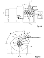
- Fig. 1B shows an alternative embodiment of the elongated feeding compartment 12 of the apparatus where the steam is removed through a radial outlet 24, instead of the axial outlet 23 in fig. 1A .
- the apparatus of fig. 1B comprises an inwards radially extending wall section 26 from an inner surface 16' in the elongated feeding compartment 12, that defines a rear chamber 27 arranged in the elongated feeding compartment 12 to which the radial outlet 24 is connected.
- the wall section is extending towards the shaft of elongated feeding compartment 12.
- the fraction of fibres are fed in the opposite direction by means of the conveyor worm 25 and are restrained to be brought into the rear chamber by the wall section.
Landscapes
- Engineering & Computer Science (AREA)
- Mechanical Engineering (AREA)
- Life Sciences & Earth Sciences (AREA)
- Wood Science & Technology (AREA)
- Paper (AREA)
- Nonwoven Fabrics (AREA)
Claims (8)
- Appareil pour séparer la vapeur d'eau d' un mélange de vapeur d'eau et de fibres, comprenant un compartiment d'alimentation de forme allongée (12) comportant un orifice d'admission (14) disposé entre les petits côtés (15, 15') du compartiment d'alimentation de forme allongée (12) et des moyens d'alimentation (10) pour fournir un mélange de vapeur d'eau et de fibres par ledit orifice d'admission (14) et une vis sans fin transporteuse (25) disposée axialement dans le compartiment d'alimentation (12) pour une alimentation en fibres, caractérisé en ce que les moyens d'alimentation (10) comportent une section tubulaire (18) qui est courbée de telle sorte que le mélange de vapeur d'eau et de fibres pendant un passage dans la section tubulaire (18) est séparé sous l'influence des forces centrifuges en une fraction essentiellement dépourvue de vapeur, relativement lourde, de fibres dans une couche extérieure de façon radiale (20) et en une fraction légère, essentiellement exempte de fibres, de vapeur dans une couche intérieure de façon radiale (22), la section tubulaire est agencée de telle manière que la fraction lourde de fibres soit fournie à travers l'orifice d'admission (14) de façon périphérique (P) dans le compartiment d'alimentation de forme allongée (12) de l'appareil, dans lequel la fraction séparée de fibres est, de plus, acheminée au moyen de la vis sans fin transporteuse (25), tandis que la fraction légère séparée de vapeur est fournie par l'orifice d'admission (14) contre le centre (C) du compartiment d'alimentation de forme allongée (12) et évacuée par un orifice de sortie (23, 24) de l'appareil.
- Dispositif selon la revendication 1, caractérisé en ce que la section tubulaire (18) est adaptée de telle façon que la différence de vitesse, entre la vitesse des fibres dans les moyens d'alimentation (10) par rapport à la vitesse de la vis sans fin transporteuse (25) disposée dans le compartiment: d'alimentation de forme allongée (12), soit réduite au minimum.
- Dispositif selon la revendication 1 ou 2, caractérisé en ce que le dispositif comporte une section de paroi s'étendant radialement vers l'intérieur (26) à partir d'une surface intérieure (16') du compartiment d'alimentation de forme allongée (12), laquelle définit une chambre arrière (27) dans l'appareil à laquelle l'orifice de sortie radial (24) est raccordé, orifice de sortie (24) par lequel la vapeur d'eau est évacuée.
- Appareil selon l'une quelconque des revendications précédentes, caractérisé en ce que les moyens d'alimentation (10) possèdent une partie tubulaire extérieure, de forme allongée, linéaire essentiellement rectiligne comportant une extension (H), laquelle partie extérieure (30) est placée de façon adjacente à une extrémité opposée (31) par rapport à l'extrémité de la section tubulaire courbe (18) qui est raccordée à l'orifice d'admission (14).
- Appareil selon la revendication 4, caractérisé en ce que l'extension (H) des moyens d'alimentation (10) forme un angle compris entre 75 et 90° par rapport à l'extension longitudinale (L) de l'appareil.
- Appareil selon l'une quelconque des revendications précédentes, caractérisé en ce que l'orifice d'admission. (14) est disposé tangentiellement au niveau de la périphérie (16) de l'appareil.
- Appareil selon l'une quelconque des revendications précédentes; caractérisé en ce que la surface de section transversale de l'orifice d'admission (14) et des moyens d'alimentation (10) est carrée ou rectangulaire.
- Procédé pour fournir un mélange de vapeur d'eau et de fibres à un compartiment d'alimentation de forme allongée (12) d'un appareil permettant de séparer la vapeur d'eau d'un mélange de vapeur d'eau et de fibres, dans lequel le mélange de vapeur d'eau et de fibres est fourni par l'intermédiaire de moyens d'alimentation (10) à travers un orifice d'admission (14) disposé entre les petits côtés (15, 15') du compartiment d'alimentation de forme allongée (12), et dans lequel les fibres sont transportées, de plus, au moyen d'une vis sans fin transporteuse (25) disposée axialement dans le compartiment d'alimentation (12), caractérisé en ce que les moyens d'alimentation (10) comportent une section tubulaire (18) qui est courbe, de sorte que le mélange de vapeur d'eau et de fibres au niveau du passage dans la section tubulaire (18) est amené à se séparer sous l'influence des forces centrifuges en une fraction de fibres essentiellement dépourvue de vapeur d'eau, relativement lourde, dans une couche extérieure de façon radiale (20) et en une fraction légère de vapeur d'eau, essentiellement dépourvue de fibres, dans une couche intérieure de façon radiale (22), en ce que la section tubulaire est agencée de telle sorte que la fraction lourde de fibres est fournie à travers l'orifice d'admission (14) de façon périphérique (P) dans le compartiment d'alimentation de forme allongée (12) de l'appareil, dans lequel la fraction séparée de fibres est acheminée, de plus, au moyen de la vis sans fin transporteuse (25), tandis que la fraction légère séparée de vapeur d'eau est fournie à travers l'orifice d'admission (14) contre le centre (C) du compartiment d'alimentation de forme allongée (12) et évacuée par un orifice de sortie (23, 24) de l'appareil.
Applications Claiming Priority (3)
| Application Number | Priority Date | Filing Date | Title |
|---|---|---|---|
| SE0203176 | 2002-10-29 | ||
| SE0203176A SE524032C2 (sv) | 2002-10-29 | 2002-10-29 | Anordning och förfarande vid framställning av pappersmassa |
| PCT/SE2003/001614 WO2004040058A1 (fr) | 2002-10-29 | 2003-10-17 | Appareil et procede de production de pate a papier |
Publications (2)
| Publication Number | Publication Date |
|---|---|
| EP1567710A1 EP1567710A1 (fr) | 2005-08-31 |
| EP1567710B1 true EP1567710B1 (fr) | 2008-04-16 |
Family
ID=20289387
Family Applications (1)
| Application Number | Title | Priority Date | Filing Date |
|---|---|---|---|
| EP03809907A Expired - Lifetime EP1567710B1 (fr) | 2002-10-29 | 2003-10-17 | Appareil et procede de production de pate a papier |
Country Status (8)
| Country | Link |
|---|---|
| EP (1) | EP1567710B1 (fr) |
| CN (1) | CN100333819C (fr) |
| AT (1) | ATE392504T1 (fr) |
| AU (1) | AU2003301686A1 (fr) |
| CA (1) | CA2503755C (fr) |
| DE (1) | DE60320445T2 (fr) |
| SE (1) | SE524032C2 (fr) |
| WO (1) | WO2004040058A1 (fr) |
Families Citing this family (2)
| Publication number | Priority date | Publication date | Assignee | Title |
|---|---|---|---|---|
| CA2872839A1 (fr) * | 2012-06-01 | 2013-12-05 | Dieffenbacher GmbH Maschinen- und Anlagenbau | Coude pour introduire un courant de vapeur et de fibres dans un sechoir ou un cuvier de stockage de la pulpe d'une usine de traitement de fibres, installation de soufflage avec un coude, et usine de traitement de fibres avec une installation de soufflage |
| SE2330364A1 (en) * | 2023-08-23 | 2024-07-23 | Valmet Oy | Steam separator |
Family Cites Families (2)
| Publication number | Priority date | Publication date | Assignee | Title |
|---|---|---|---|---|
| SE468015B (sv) * | 1987-04-15 | 1992-10-19 | Sunds Defibrator Ind Ab | Anlaeggning foer framstaellning av fibermassa av lignocellulosamaterial |
| SE514165C2 (sv) * | 1999-05-12 | 2001-01-15 | Valmet Fibertech Ab | Avskiljningsanordning |
-
2002
- 2002-10-29 SE SE0203176A patent/SE524032C2/sv not_active IP Right Cessation
-
2003
- 2003-10-17 AT AT03809907T patent/ATE392504T1/de active
- 2003-10-17 CA CA2503755A patent/CA2503755C/fr not_active Expired - Lifetime
- 2003-10-17 EP EP03809907A patent/EP1567710B1/fr not_active Expired - Lifetime
- 2003-10-17 CN CNB2003801020708A patent/CN100333819C/zh not_active Expired - Lifetime
- 2003-10-17 WO PCT/SE2003/001614 patent/WO2004040058A1/fr not_active Ceased
- 2003-10-17 AU AU2003301686A patent/AU2003301686A1/en not_active Abandoned
- 2003-10-17 DE DE60320445T patent/DE60320445T2/de not_active Expired - Lifetime
Also Published As
| Publication number | Publication date |
|---|---|
| SE524032C2 (sv) | 2004-06-15 |
| DE60320445D1 (de) | 2008-05-29 |
| CA2503755A1 (fr) | 2004-05-13 |
| EP1567710A1 (fr) | 2005-08-31 |
| CN100333819C (zh) | 2007-08-29 |
| ATE392504T1 (de) | 2008-05-15 |
| WO2004040058A1 (fr) | 2004-05-13 |
| CN1708614A (zh) | 2005-12-14 |
| DE60320445T2 (de) | 2009-07-09 |
| CA2503755C (fr) | 2011-08-09 |
| SE0203176D0 (sv) | 2002-10-29 |
| SE0203176L (sv) | 2004-04-30 |
| AU2003301686A1 (en) | 2004-05-25 |
Similar Documents
| Publication | Publication Date | Title |
|---|---|---|
| EP1888248B1 (fr) | Unite hydrocyclone et procede de separation d une suspension de pate fibreuse contenant des contaminants relativements lourds | |
| US7001324B2 (en) | Method of retrofitting a decanting centrifuge | |
| US4309283A (en) | Hydrocyclone | |
| US4510056A (en) | Hydrocyclone separator | |
| US4153558A (en) | Hydrocyclone separator | |
| FI93374C (fi) | Laite kuitupitoisen selluloosamassan suspension jakamiseksi | |
| EP0095382A2 (fr) | Séparateurs cyclones | |
| US4991720A (en) | Apparatus for dividing a suspension of fibrous cellulose pulp | |
| EP0306022B1 (fr) | Procédé et dispositif pour classer une suspension de fibre | |
| EP1567710B1 (fr) | Appareil et procede de production de pate a papier | |
| US7691235B2 (en) | Apparatus and method for separating steam from pulp fibers | |
| CA2232665C (fr) | Dispositif d'epuration | |
| JP2008513625A (ja) | 水性の紙繊維懸濁液を分別するための方法ならびに該方法を実施するためのハイドロサイクロン | |
| US4222863A (en) | Screening apparatus and method | |
| US5323914A (en) | Method of and apparatus for separating heavy impurities from fiber suspensions in connection with pumping | |
| US6530481B1 (en) | Pressure screen with scrap separation | |
| EP0649369B1 (fr) | Installation de separation a temperature elevee de divers contaminants a partir d'une matiere plastique particulaire ou lamelleuse | |
| EP1159482B1 (fr) | Dispositif de tamisage | |
| EP0643785A1 (fr) | Appareil et procede permettant de filtrer une suspension de pate a papier | |
| WO2000069543A1 (fr) | Dispositif de separation | |
| SU1178493A1 (ru) | Гидроциклон | |
| WO1998045532A1 (fr) | Dispositif de separation |
Legal Events
| Date | Code | Title | Description |
|---|---|---|---|
| PUAI | Public reference made under article 153(3) epc to a published international application that has entered the european phase |
Free format text: ORIGINAL CODE: 0009012 |
|
| 17P | Request for examination filed |
Effective date: 20050525 |
|
| AK | Designated contracting states |
Kind code of ref document: A1 Designated state(s): AT BE BG CH CY CZ DE DK EE ES FI FR GB GR HU IE IT LI LU MC NL PT RO SE SI SK TR |
|
| AX | Request for extension of the european patent |
Extension state: AL LT LV MK |
|
| DAX | Request for extension of the european patent (deleted) | ||
| 17Q | First examination report despatched |
Effective date: 20061206 |
|
| GRAP | Despatch of communication of intention to grant a patent |
Free format text: ORIGINAL CODE: EPIDOSNIGR1 |
|
| GRAS | Grant fee paid |
Free format text: ORIGINAL CODE: EPIDOSNIGR3 |
|
| GRAA | (expected) grant |
Free format text: ORIGINAL CODE: 0009210 |
|
| AK | Designated contracting states |
Kind code of ref document: B1 Designated state(s): AT BE BG CH CY CZ DE DK EE ES FI FR GB GR HU IE IT LI LU MC NL PT RO SE SI SK TR |
|
| REG | Reference to a national code |
Ref country code: CH Ref legal event code: EP |
|
| REG | Reference to a national code |
Ref country code: IE Ref legal event code: FG4D |
|
| REF | Corresponds to: |
Ref document number: 60320445 Country of ref document: DE Date of ref document: 20080529 Kind code of ref document: P |
|
| REG | Reference to a national code |
Ref country code: SE Ref legal event code: TRGR |
|
| PG25 | Lapsed in a contracting state [announced via postgrant information from national office to epo] |
Ref country code: SI Free format text: LAPSE BECAUSE OF FAILURE TO SUBMIT A TRANSLATION OF THE DESCRIPTION OR TO PAY THE FEE WITHIN THE PRESCRIBED TIME-LIMIT Effective date: 20080416 |
|
| NLV1 | Nl: lapsed or annulled due to failure to fulfill the requirements of art. 29p and 29m of the patents act | ||
| PG25 | Lapsed in a contracting state [announced via postgrant information from national office to epo] |
Ref country code: BG Free format text: LAPSE BECAUSE OF FAILURE TO SUBMIT A TRANSLATION OF THE DESCRIPTION OR TO PAY THE FEE WITHIN THE PRESCRIBED TIME-LIMIT Effective date: 20080716 Ref country code: ES Free format text: LAPSE BECAUSE OF FAILURE TO SUBMIT A TRANSLATION OF THE DESCRIPTION OR TO PAY THE FEE WITHIN THE PRESCRIBED TIME-LIMIT Effective date: 20080727 Ref country code: NL Free format text: LAPSE BECAUSE OF FAILURE TO SUBMIT A TRANSLATION OF THE DESCRIPTION OR TO PAY THE FEE WITHIN THE PRESCRIBED TIME-LIMIT Effective date: 20080416 Ref country code: PT Free format text: LAPSE BECAUSE OF FAILURE TO SUBMIT A TRANSLATION OF THE DESCRIPTION OR TO PAY THE FEE WITHIN THE PRESCRIBED TIME-LIMIT Effective date: 20080916 |
|
| ET | Fr: translation filed | ||
| PG25 | Lapsed in a contracting state [announced via postgrant information from national office to epo] |
Ref country code: DK Free format text: LAPSE BECAUSE OF FAILURE TO SUBMIT A TRANSLATION OF THE DESCRIPTION OR TO PAY THE FEE WITHIN THE PRESCRIBED TIME-LIMIT Effective date: 20080416 Ref country code: CZ Free format text: LAPSE BECAUSE OF FAILURE TO SUBMIT A TRANSLATION OF THE DESCRIPTION OR TO PAY THE FEE WITHIN THE PRESCRIBED TIME-LIMIT Effective date: 20080416 |
|
| PLBE | No opposition filed within time limit |
Free format text: ORIGINAL CODE: 0009261 |
|
| STAA | Information on the status of an ep patent application or granted ep patent |
Free format text: STATUS: NO OPPOSITION FILED WITHIN TIME LIMIT |
|
| PG25 | Lapsed in a contracting state [announced via postgrant information from national office to epo] |
Ref country code: RO Free format text: LAPSE BECAUSE OF FAILURE TO SUBMIT A TRANSLATION OF THE DESCRIPTION OR TO PAY THE FEE WITHIN THE PRESCRIBED TIME-LIMIT Effective date: 20080416 Ref country code: SK Free format text: LAPSE BECAUSE OF FAILURE TO SUBMIT A TRANSLATION OF THE DESCRIPTION OR TO PAY THE FEE WITHIN THE PRESCRIBED TIME-LIMIT Effective date: 20080416 Ref country code: BE Free format text: LAPSE BECAUSE OF FAILURE TO SUBMIT A TRANSLATION OF THE DESCRIPTION OR TO PAY THE FEE WITHIN THE PRESCRIBED TIME-LIMIT Effective date: 20080416 |
|
| 26N | No opposition filed |
Effective date: 20090119 |
|
| PGFP | Annual fee paid to national office [announced via postgrant information from national office to epo] |
Ref country code: IT Payment date: 20081023 Year of fee payment: 6 |
|
| PG25 | Lapsed in a contracting state [announced via postgrant information from national office to epo] |
Ref country code: EE Free format text: LAPSE BECAUSE OF FAILURE TO SUBMIT A TRANSLATION OF THE DESCRIPTION OR TO PAY THE FEE WITHIN THE PRESCRIBED TIME-LIMIT Effective date: 20080416 |
|
| PGFP | Annual fee paid to national office [announced via postgrant information from national office to epo] |
Ref country code: FR Payment date: 20080930 Year of fee payment: 6 |
|
| PG25 | Lapsed in a contracting state [announced via postgrant information from national office to epo] |
Ref country code: MC Free format text: LAPSE BECAUSE OF NON-PAYMENT OF DUE FEES Effective date: 20081031 |
|
| REG | Reference to a national code |
Ref country code: CH Ref legal event code: PL |
|
| GBPC | Gb: european patent ceased through non-payment of renewal fee |
Effective date: 20081017 |
|
| PG25 | Lapsed in a contracting state [announced via postgrant information from national office to epo] |
Ref country code: CY Free format text: LAPSE BECAUSE OF FAILURE TO SUBMIT A TRANSLATION OF THE DESCRIPTION OR TO PAY THE FEE WITHIN THE PRESCRIBED TIME-LIMIT Effective date: 20080416 |
|
| PG25 | Lapsed in a contracting state [announced via postgrant information from national office to epo] |
Ref country code: LI Free format text: LAPSE BECAUSE OF NON-PAYMENT OF DUE FEES Effective date: 20081031 Ref country code: IE Free format text: LAPSE BECAUSE OF NON-PAYMENT OF DUE FEES Effective date: 20081017 Ref country code: CH Free format text: LAPSE BECAUSE OF NON-PAYMENT OF DUE FEES Effective date: 20081031 |
|
| PG25 | Lapsed in a contracting state [announced via postgrant information from national office to epo] |
Ref country code: GB Free format text: LAPSE BECAUSE OF NON-PAYMENT OF DUE FEES Effective date: 20081017 |
|
| REG | Reference to a national code |
Ref country code: FR Ref legal event code: ST Effective date: 20100630 |
|
| PG25 | Lapsed in a contracting state [announced via postgrant information from national office to epo] |
Ref country code: HU Free format text: LAPSE BECAUSE OF FAILURE TO SUBMIT A TRANSLATION OF THE DESCRIPTION OR TO PAY THE FEE WITHIN THE PRESCRIBED TIME-LIMIT Effective date: 20081017 Ref country code: LU Free format text: LAPSE BECAUSE OF NON-PAYMENT OF DUE FEES Effective date: 20081017 Ref country code: FR Free format text: LAPSE BECAUSE OF NON-PAYMENT OF DUE FEES Effective date: 20091102 |
|
| PG25 | Lapsed in a contracting state [announced via postgrant information from national office to epo] |
Ref country code: TR Free format text: LAPSE BECAUSE OF FAILURE TO SUBMIT A TRANSLATION OF THE DESCRIPTION OR TO PAY THE FEE WITHIN THE PRESCRIBED TIME-LIMIT Effective date: 20080416 |
|
| PG25 | Lapsed in a contracting state [announced via postgrant information from national office to epo] |
Ref country code: GR Free format text: LAPSE BECAUSE OF FAILURE TO SUBMIT A TRANSLATION OF THE DESCRIPTION OR TO PAY THE FEE WITHIN THE PRESCRIBED TIME-LIMIT Effective date: 20080717 |
|
| PG25 | Lapsed in a contracting state [announced via postgrant information from national office to epo] |
Ref country code: IT Free format text: LAPSE BECAUSE OF NON-PAYMENT OF DUE FEES Effective date: 20091017 |
|
| PGFP | Annual fee paid to national office [announced via postgrant information from national office to epo] |
Ref country code: SE Payment date: 20221017 Year of fee payment: 20 Ref country code: FI Payment date: 20221020 Year of fee payment: 20 Ref country code: DE Payment date: 20221019 Year of fee payment: 20 Ref country code: AT Payment date: 20221020 Year of fee payment: 20 |
|
| REG | Reference to a national code |
Ref country code: DE Ref legal event code: R071 Ref document number: 60320445 Country of ref document: DE |
|
| REG | Reference to a national code |
Ref country code: SE Ref legal event code: EUG |
|
| REG | Reference to a national code |
Ref country code: AT Ref legal event code: MK07 Ref document number: 392504 Country of ref document: AT Kind code of ref document: T Effective date: 20231017 |