EP1568576A2 - Système de direction et procédé pour la commande du système de direction - Google Patents
Système de direction et procédé pour la commande du système de direction Download PDFInfo
- Publication number
- EP1568576A2 EP1568576A2 EP05001538A EP05001538A EP1568576A2 EP 1568576 A2 EP1568576 A2 EP 1568576A2 EP 05001538 A EP05001538 A EP 05001538A EP 05001538 A EP05001538 A EP 05001538A EP 1568576 A2 EP1568576 A2 EP 1568576A2
- Authority
- EP
- European Patent Office
- Prior art keywords
- steering
- angle
- motor vehicle
- steering system
- wheel
- Prior art date
- Legal status (The legal status is an assumption and is not a legal conclusion. Google has not performed a legal analysis and makes no representation as to the accuracy of the status listed.)
- Granted
Links
- 238000000034 method Methods 0.000 title claims abstract description 16
- 238000004590 computer program Methods 0.000 claims abstract description 21
- 230000006870 function Effects 0.000 claims description 95
- 238000001514 detection method Methods 0.000 claims description 7
- 238000001914 filtration Methods 0.000 claims description 6
- 230000001419 dependent effect Effects 0.000 claims description 5
- 238000010586 diagram Methods 0.000 description 10
- 230000001133 acceleration Effects 0.000 description 9
- 230000003750 conditioning effect Effects 0.000 description 9
- 230000008859 change Effects 0.000 description 7
- 238000005070 sampling Methods 0.000 description 7
- 230000005540 biological transmission Effects 0.000 description 5
- 238000012544 monitoring process Methods 0.000 description 5
- 238000013519 translation Methods 0.000 description 5
- 230000014616 translation Effects 0.000 description 5
- 230000008901 benefit Effects 0.000 description 4
- 238000004422 calculation algorithm Methods 0.000 description 4
- 238000004364 calculation method Methods 0.000 description 4
- 239000012530 fluid Substances 0.000 description 3
- 238000012545 processing Methods 0.000 description 3
- 230000003111 delayed effect Effects 0.000 description 2
- 230000003287 optical effect Effects 0.000 description 2
- 231100000614 poison Toxicity 0.000 description 2
- 230000007096 poisonous effect Effects 0.000 description 2
- 238000002360 preparation method Methods 0.000 description 2
- 230000009471 action Effects 0.000 description 1
- 230000006978 adaptation Effects 0.000 description 1
- 230000015572 biosynthetic process Effects 0.000 description 1
- 238000012937 correction Methods 0.000 description 1
- 238000007598 dipping method Methods 0.000 description 1
- 238000009826 distribution Methods 0.000 description 1
- 238000009472 formulation Methods 0.000 description 1
- 230000003993 interaction Effects 0.000 description 1
- 239000000203 mixture Substances 0.000 description 1
- 230000008447 perception Effects 0.000 description 1
- 238000007781 pre-processing Methods 0.000 description 1
- 230000000630 rising effect Effects 0.000 description 1
- 230000003068 static effect Effects 0.000 description 1
Images


Classifications
-
- B—PERFORMING OPERATIONS; TRANSPORTING
- B62—LAND VEHICLES FOR TRAVELLING OTHERWISE THAN ON RAILS
- B62D—MOTOR VEHICLES; TRAILERS
- B62D6/00—Arrangements for automatically controlling steering depending on driving conditions sensed and responded to, e.g. control circuits
- B62D6/002—Arrangements for automatically controlling steering depending on driving conditions sensed and responded to, e.g. control circuits computing target steering angles for front or rear wheels
- B62D6/006—Arrangements for automatically controlling steering depending on driving conditions sensed and responded to, e.g. control circuits computing target steering angles for front or rear wheels using a measured or estimated road friction coefficient
-
- B—PERFORMING OPERATIONS; TRANSPORTING
- B62—LAND VEHICLES FOR TRAVELLING OTHERWISE THAN ON RAILS
- B62D—MOTOR VEHICLES; TRAILERS
- B62D5/00—Power-assisted or power-driven steering
- B62D5/008—Changing the transfer ratio between the steering wheel and the steering gear by variable supply of energy, e.g. by using a superposition gear
-
- B—PERFORMING OPERATIONS; TRANSPORTING
- B62—LAND VEHICLES FOR TRAVELLING OTHERWISE THAN ON RAILS
- B62D—MOTOR VEHICLES; TRAILERS
- B62D6/00—Arrangements for automatically controlling steering depending on driving conditions sensed and responded to, e.g. control circuits
- B62D6/001—Arrangements for automatically controlling steering depending on driving conditions sensed and responded to, e.g. control circuits the torque NOT being among the input parameters
-
- B—PERFORMING OPERATIONS; TRANSPORTING
- B62—LAND VEHICLES FOR TRAVELLING OTHERWISE THAN ON RAILS
- B62D—MOTOR VEHICLES; TRAILERS
- B62D6/00—Arrangements for automatically controlling steering depending on driving conditions sensed and responded to, e.g. control circuits
- B62D6/007—Arrangements for automatically controlling steering depending on driving conditions sensed and responded to, e.g. control circuits adjustable by the driver, e.g. sport mode
Definitions
- the present invention relates to a steering system of a Motor vehicle.
- the steering system includes a steering handle to specify a steering wheel angle as a measure of one desired steering angle for at least one steerable wheel of Motor vehicle. It also includes the steering system Overlay means for generating an additional angle and for superposition of the steering wheel angle with the additional angle. The angle resulting from the overlay is called Pinion angle called.
- the steering system includes a steering gear to implement the pinion angle in a corrected steering angle for the at least one steerable Wheel of the motor vehicle.
- the invention relates to a method of operation a steering system of a motor vehicle. It is by means of a steering handle a steering wheel angle as a measure of a desired steering angle for at least one steerable wheel of Motor vehicle specified. In addition, an additional angle generated and to determine a pinion angle the Steering wheel angle superimposed. Finally, the pinion angle in a corrected steering angle for the at least one steerable wheel of the motor vehicle implemented.
- the present invention relates to a Computer program running on a computing device, in particular on a microprocessor, a controller for a Steering system of a motor vehicle is executable.
- a steering system of the type mentioned with Overlay means is for example from the DE 40 31 316 A1.
- overlay means it is possible to set one of the steering handle Steering wheel angle to increase the driving stability and / or the Comfort with an additional angle to superimpose, so that Depending on the driving dynamics and / or comfort, a variable Transmission ratio between steering wheel angle and Set pinion angle. This makes it safety-related possible, a motor vehicle that threatens to break through a corresponding correction of the steering angle back into a Stable driving situation due.
- the overlay means can vehicle dynamics means of the motor vehicle (eg. an Electronic Stability Program (ESP) Anti-lock braking system (ABS), a traction control system (ASR), etc.).
- ESP Electronic Stability Program
- ABS Anti-lock braking system
- ASR traction control system
- a yaw rate control in which over the Steering system correcting the driving dynamics of the Motor vehicle is intervened to increase the yaw rate to one settable value and thereby breaking out to avoid the vehicle.
- a relatively small Set ratio that is, a rotation the steering handle by a certain angle of rotation leads to a relatively large steering angle of the wheels.
- a steering system of the type mentioned is for example, also known from DE 100 13 711 A1.
- the servo drive can be electric or hydraulic work.
- the degree of torque support can be dependent chosen from the driving speed of the motor vehicle become. While at slower speeds the Torque support is greater (for example, at Maneuvering the vehicle without the big steering wheel To be able to press force), is the Torque support at higher speeds (for Example to the driving stability in a highway trip to increase) significantly smaller.
- the invention Steering system can have a servo drive. The invention But it is also important for such steering systems, the do not have a servo drive.
- the present invention is based on the object, the Handling of motor vehicles with steering systems are equipped of the type mentioned, continue to improve.
- the Superposition means the additional angle as a function of generate a driving situation of the motor vehicle.
- the current Driving situation of the motor vehicle or else Driving situations at past times to Determining the additional angle to use Since that Transmission ratio (the so-called steering ratio) between steering handle and pinion of the steering gear of the Size of the additional angle is dependent, so is the Gear ratio depending on the Driving situation varies.
- the driving situation of a Motor vehicle for example, in a "sporty” and a “restrained” driving style be divided.
- the current driving situation of the Motor vehicle can be based on one or more suitable operating variables of the motor vehicle, such as for example, wheel speed, vehicle acceleration, Frequency and intensity (speed, acceleration) an operation of accelerator pedal and brake pedal, intensity (Speed, acceleration) of an actuation of the Steering handle (for example, recorded on the Steering wheel angular velocity).
- suitable operating variables of the motor vehicle such as for example, wheel speed, vehicle acceleration, Frequency and intensity (speed, acceleration) an operation of accelerator pedal and brake pedal, intensity (Speed, acceleration) of an actuation of the Steering handle (for example, recorded on the Steering wheel angular velocity).
- the funds are for example, as mounted in the area of the vehicle wheels Speed sensors formed.
- Speed sensors eg for Vehicle Dynamics, Electronic Stability Control (ESR), Antilock Braking System (ABS), etc.
- Speed sensors are used.
- it can also own speed sensors on one or more wheels of Vehicle be provided.
- the information about the Speed of the wheels can still be controlled by other operating variables be added to the reliability of the detection of a Driving situation and the validity of the detected Improve driving situation.
- the superposition means the Additional angle as a function of the steering wheel angle generate characterizing size.
- the steering ratio So also depending on the angle of the steering handle be varied.
- the steering wheel angle can also Angle of the pinion of the steering gear or any other variable characterizing the steering wheel angle, be used.
- the overlay means the Additional angle depending on a Rotational speed of the steering handle characterizing Generate size.
- the steering ratio so also in Dependence on the change of the steering wheel angle per Time unit (from the first derivative of the steering wheel angle) be varied.
- the rotational speed of the Steering handle can also change the speed of rotation of the pinion of the steering gear or any other, the Rotational speed of the steering handle characterizing Size, be used.
- the Superposition means the additional angle as a function of a preferably non-linear steering kinematics of Generate steering gear. This is in advance of the Steering kinematics determined and at least their non-linear Shares in determining the steering ratio considered.
- Nonlinearities of steering kinematics have its cause, for example, in that the steering gear no constant gearing between the pinion and one Rack has.
- Steering kinematics between pinion angle and steering angle can be Steering ratio not only between steering handle and pinion, but even between the steering handle and steering angle of the Wheels are given. This makes it possible for the Adjust steering ratio of the steering system such a Actuation of the steering handle to a certain way leads a predetermined impact of the steerable wheels.
- the steering system means for execution of a filter coefficient defined Filtering to determine the driving situation of the Motor vehicle used variables, the pinion angle characterizing size and / or the the Rotational speed of the steering handle characterizing Has size, the filter coefficients in Dependence on dynamic properties of the Motor vehicle specific vehicle can be specified.
- the Filtering the signals of the input variables are through Signal interference caused peaks (so-called peaks) of the Signals reduced and errors outside of a working range filtered out. Errors within the working area not filtered out.
- the extension of the Effective range is determined by the filter coefficients affected.
- the steering system means of detection an error determining the driving situation of the driver Motor vehicle used variables, the pinion angle characterizing size and / or the the Rotational speed of the steering handle characterizing Having size, wherein in case of detection of an error instead of the incorrect size, a predefinable substitute size used to generate the additional angle.
- the signals of the input variables monitored and in the event of an error instead of the input a Replacement size used to determine the steering ratio.
- the monitoring of the signals of the input variables can be a Plausibility check, gradient monitoring and include any other types of monitoring.
- the Replacement size can be an artificial, safe size. she can constant in time, but also variable.
- the means for detection an error determining the driving situation of the driver Motor vehicle used variables, the pinion angle characterizing size and / or the the Rotational speed of the steering handle characterizing Size in the case of detection of a defect-free size instead the replacement size again the correct size to generate of the additional angle is used.
- the signals of the input variables further observed and from a replacement size back to appropriate Switched input, if the signal of the Input size is error-free again.
- the overlay means comprise a Electric motor for generating the additional angle and a Superposition gear for superimposing the steering wheel angle with the additional angle, the engine in the range of Stop the steering gear of a predetermined function is driven to zero following.
- a can so-called soft-stop function can be realized in the the steering just before reaching an end stop of the Steering gear or any other end stop is gently braked.
- the braking can be up to Standstill of the steering go, so that way a kind of virtual electronic end stop could be realized, even before the mechanical Stop is arranged. That allows a special one gentle operation of the steering system.
- the steering system has a servo drive for torque assistance.
- the degree of torque assistance is of the Driving speed of the motor vehicle dependent.
- the pinion angle of a steering gear in the corrected steering angle for the at least one steerable Wheel of the motor vehicle is implemented and that of the Additional angle as a function of a preferably non-linear Steering kinematics of the steering gear is generated.
- the computer program is on one Computing device, in particular on a microprocessor, executable and for the execution of the invention Suitable method.
- the invention realized by the computer program, so this Computer program in the same way represents the invention like the method to which it is used Computer program is programmed.
- the computer program is preferably stored on a memory element.
- Memory element may in particular an electrical Storage medium are used, for example, a Random access memory, a read-only memory or a Flash memory.
- the memory element can also be used as a magnetic storage medium (eg floppy disk, hard disk, Memory tape) or optical storage medium (eg DVD, CD-ROM, etc.).
- FIG. 1 shows a steering system according to the invention Motor vehicle in its entirety by the reference numeral 1 designated.
- the steering system 1 comprises a steering handle 2, for example, as a steering wheel, as a handlebar or can be designed as a steering stick.
- the Steering handle 2 is about a propeller shaft 3 with a Steering gear 4 in conjunction.
- the propeller shaft 3 is depending on Embodiment of the steering system 1 by one or more Cardan joints 5, 6 interrupted.
- the steering gear 4 is used to a rotation angle of the propeller shaft 3 in a Steering angle ⁇ _F of wheels to be steered 12, 13 of the Implement motor vehicle.
- the steering gear 4 comprises in the embodiment shown in Figure 1 a Rack 7 and a pinion 8, to which the propeller shaft. 3 attacks.
- the steering system 1 also has Superposition means 9, which has an electric motor 10 and a driven by this superposition gear 11 in Form of a planetary gear include.
- a steering wheel angle ⁇ _S as a measure for a desired steering angle ⁇ _F of the steerable wheels 12, 13 of the motor vehicle specified.
- the engine 10 of the superposition means 9 can be an additional angle ⁇ _M generated and the steering wheel angle ⁇ _S by means of Overlay gear 11 are superimposed.
- the Additional angle ⁇ _M is used to improve the driving dynamics of the Motor vehicle and / or comfort generated.
- the Summation angle of steering wheel angle ⁇ _S and additional angle ⁇ _M is referred to as pinion angle ⁇ _G.
- a servo drive 14th In the region of the steering gear 4 is a servo drive 14th arranged, which serves for moment support.
- the Servo drive 14 includes a hydraulic pump 15, which is a Hydraulic fluid from a reservoir 16 via a Hydraulic valve 17 promotes the steering gear 4.
- the Hydraulic valve 17 is electromagnetic or via a Piezo actuator can be actuated.
- Hydraulic fluid can be the strength of Momentsupport can be varied.
- hydraulic servo drive 14 may also be a electric servo drive are provided.
- the present invention has the stated advantages also in steering systems 1, the no servo drive 14th exhibit.
- the steering system 1 also has a control unit 19, Among other things, to control the motor 10 of Superposition means 9 and the hydraulic valve 17 of the Servo drive 14 is used.
- the hydraulic valve 17 is so that depends on the Driving speed V_x of the motor vehicle a variable Moments support set. That's the way it is, for example possible, at low speeds V_x a high To select torque assistance to maneuver the Facilitate vehicles and at high speeds V_x (eg for speedy overland or motorway travel) one to set low torque assistance to one driving dynamics particularly stable steering of the vehicle too enable.
- the Control of the motor 10 of the superposition means 9 under depending on a driving situation of the Motor vehicle. It is therefore proposed that Steering ratio between the steering wheel angle ⁇ _S the Steering handle 2 and the pinion angle ⁇ _G of the pinion 8 of the Steering gear 4 and a steering angle ⁇ _F the steerable Wheels 12, 13 depending on the driving situation vary.
- a driving situation in the sense of the Present invention arbitrary driving situations of a Motor vehicle except the vehicle speed V_x considered alone. Of course but also such driving situations are considered, the among others are also dependent on the Vehicle speed V_x.
- a driving situation in the sense The present invention is therefore not alone an isolated operating size of the motor vehicle, for example, solely by the vehicle speed V_x, but rather through an interaction of several of different farm sizes, of which the Vehicle speed V_x can be one. These Farm sizes are at least partially determined analyzed and evaluated to the specific driving situation the motor vehicle as reliable and detailed as possible determine.
- the Superposition means 9 driven such that he Additional angle ⁇ _M generated depending on the driving situation.
- to Variation of the steering ratio can be the current Driving situation of the motor vehicle or else Driving situations at past times be taken into account.
- the driving situation of a Motor vehicle for example, in a "sporty” and a “restrained” driving style be divided.
- an arbitrarily large number of different driving situations for a motor vehicle be defined, with each driving situation an optimal Steering ratio is assigned, then is set depending on the driving situation.
- the driving dynamics the results in a critical driving situation.
- the driving dynamics For example, by the tire-road contact, the Properties of the chassis, vehicle geometries and Mass distributions, steering and braking intervention and influenced electronic vehicle dynamics systems.
- Driving situations of a motor vehicle are skidding, Emergency brakes, abrupt evasion, rollover, side tilt when cornering, dipping when accelerating or Braking and wheel slip.
- the current driving situation of the motor vehicle can be determined for example on the basis of the vehicle dynamics ⁇ _S, a lateral acceleration of the vehicle, a longitudinal acceleration / deceleration of the vehicle, a yaw rate of the vehicle and a float and roll angle of the vehicle ,
- the driving situation can be based on one or more suitable operating variables of the motor vehicle, such as wheel speed n, vehicle acceleration V ⁇ x , frequency and intensity (speed, acceleration) of an operation of the accelerator pedal and brake pedal, intensity (speed, acceleration) of an actuation of the steering handle 2 (FIG. detected, for example, via the steering wheel angular velocity ⁇ ⁇ S ) or pinion angle ⁇ _G. Additional information can be used to determine a specific driving situation as a redundancy for checking other measured values: longitudinal and lateral acceleration of the vehicle, steering angle ⁇ _S, slip angle on all vehicle wheels, camber and pitch angle of the vehicle and steering wheel torque.
- the current driving situation can be stored in a memory and at later times as a driving situation to a past time (for example, to a previous one Right clock).
- Steering system 1 can be the steering in certain driving situations agile, d. H. more direct or "poisonous", and in others Situations carrier, d. H. indirect or good-natured, be set. Apart from the higher driving pleasure, This can also achieve a significant safety benefit become.
- the steering system 1 Speed sensors 28, 29 for determining the speed n_12 and n_13 of the steerable wheels 12, 13 and preferably also the other wheels of the vehicle has. Based on Speed n_12, n_13 of the wheels 12, 13 can be on simple and inexpensive way a reliable and make a meaningful statement about the driving situation.
- sensors can already be on board the vehicle located driving dynamics systems, for example from a Electronic Stability Program (ESP) or a Brake assistants, to detect a specific Driving situation of the vehicle can be used.
- ESP Electronic Stability Program
- the steering system 1 has suitable Rotation angle sensors 20, 21, 22, which the steering wheel angle ⁇ _S, the additional angle ⁇ _M and the pinion angle ⁇ _G measure.
- the steering system 1 of the invention does not always have all having rotational angle sensors 20, 21, 22 shown. It is quite possible that one of the angles is not needed is modeled or based on the other two angles can be.
- the inventive method for the variation of Steering ratio of the steering system 1 is preferably in shape a computer program realized on a Computing device 23, in particular on a microprocessor, the Control unit 19 of the steering system 1 can run.
- the Computer program is on a memory element in particular on an electrical storage element 24 in Form of a read-only memory, random access memory or flash memory, saved.
- the execution of the Computer program on the computing device 23 is the erfindungsgemä.Verfahren executed.
- determined or received Values can be sent over the data link 25 to the Memory element 24 is transmitted and stored there become.
- the computer program can be accessed from the Internet 26 downloaded and stored in the memory element 24 of Control unit 19 are stored.
- the Computer program also on a memory element 27, especially on an electrical data medium (SD card, CF card, etc.), a magnetic disk (floppy disk, Hard disk, storage tape, etc.) or an optical Data carrier (CD-ROM, DVD, etc.), to be stored.
- an electrical data medium SD card, CF card, etc.
- a magnetic disk floppy disk, Hard disk, storage tape, etc.
- an optical Data carrier CD-ROM, DVD, etc.
- the object of the inventive method is that Transmission ratio between the steering wheel angle ⁇ _S and the mean angle ⁇ _Fm of the steerable wheels 12, 13 of the Adapt the driving situation.
- FIG. 2 details the method according to the invention explained.
- the Function inputs steering wheel angle ⁇ _S, status VSR_Status (VSR: variable steering ratio) of the steering system 1, Vehicle speed V_x and pinion angle ⁇ _G, specified.
- the Function outputs status signal VSR_LED, partial setpoint for the additional angle ⁇ _Md_VSR and version number v_VSR, specified.
- a trigger input is available.
- the forest is running with one constant sampling time of, for example, 1 ms.
- One Signal generator (not shown) generated on Trigger input, for example, a 0/1 edge every 10 ms, which leads to the execution of the function of Figure 2.
- the Function was for a constant sampling time of For example, 10 ms developed since the regulation of the situation of the motor 10 reads only every 10 ms a new setpoint.
- FIG. 2 shows the structure of the function for variable specification the steering ratio.
- the following are the individual Subfunctions briefly explained.
- the applicable Customer parameters are described with reference to FIG last explained.
- a subfunction 30 are the Signals vehicle speed V_x, pinion angle ⁇ _G and Steering wheel angle ⁇ _S filtered, their gradients become monitored and there will be appropriate action in case of failure individual signals initiated.
- This subfunction 30 is in Detail shown in Figure 4.
- a subfunction 31 is based on the input variables V_x, ⁇ _G, ⁇ _S and the Function status VSR_status a desired translation i_V set for further calculation. This subfunction 31 is shown in detail in FIG.
- the partial setpoint ⁇ _Md for the motor angle ⁇ _M is calculated completely at the positional level and not at the translation level as previously usual, resulting in a higher accuracy of the calculation.
- a preferably non-linear steering kinematics of the steering gear 4 that is, the non-linear relationship between pinion angle ⁇ _G of the steering gear 4 and mean front wheel angle ⁇ _Fm of the wheels 12, 13, is taken into account.
- ⁇ G f SG ( ⁇ fm )
- i_M is the ratio between the steering handle 2 and the propeller shaft 3
- i_D the ratio between the engine 10 and the propeller shaft 3
- ⁇ _S the steering wheel angle
- i_Vd the desired ratio between the steering handle 2 and the steerable wheels 12, 13.
- the non-linear relationship between the pinion 8 and the wheels 12, 13 additionally enters the calculation according to equation (4).
- the desired translation i_Vd is used in the function according to FIG 2 determined via a map.
- i_Vd depends on the current vehicle speed V_x and the current present pinion angle amount
- An example of one such map is shown in Figure 3.
- FIG. 4 shows a subsystem which contains the signal conditioning of the input signals. These are explained below.
- the steering wheel angle ⁇ _S is first limited to ⁇ 800 ° (function block 50).
- a gradient limitation in a function block 51.
- the permissible change per sampling step is determined on the basis of the parameterizable permissible maximum gradient max_grad. If this is exceeded, the gradient limitation determines the new value based on the value from the previous step and adds or subtracts from this the maximum permissible gradient max_grad.
- the functional status is in a function block 41 limited, for example, to a permissible value range from -2 to +5.
- the function block 42, the VSR_LED (light emitting diode) turns active when the functional status VSR_status is greater than or equal to zero. Otherwise the LED will be off.
- VSR_LED light emitting diode
- the signal processing of the vehicle speed V_x takes place in a function block 43, which is shown in detail in FIG 6 is shown.
- a selection block 60 depending on the applied functional status VSR_status between the sensor signal V_x and a constant value V_x_max switched. Is an error in the Speed signal V_x detected, the Function status VSR_status switched so that a safe fallback level can be taken.
- a function block 61 a Gradient monitoring. Will be a maximum allowable Gradient value max_grad exceeded, this is considered a Change of function status VSR_status evaluated. With one Sampling step delay (function block 62) becomes the maximum allowed gradient grad_check_OK in one Function block 63 changed to a smaller value. This will cause the status change Jump in the sensor signal avoided and the new setpoint gradually approached.
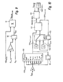
- the signal conditioning of the pinion angle ⁇ _G takes place at the function of Figure 4 in a function block 44, the in Figure 7 is shown in detail.
- that is Signal conditioning of the pinion angle ⁇ _G identical to the Preparation of vehicle speed V x.
- Reference numeral 70 is a switching element for switching between the sensor signal ⁇ _G and a constant value ⁇ _G_final depending on the connected function status VSR_status is called.
- Function block 71 is a Gradient monitoring
- reference numeral 72 is a Delay element for delaying the maximum permissible Gradient grad_check_OK by one sampling step. In one Function block 73 becomes the delayed maximum allowable Gradient grad_check_OK changed to a smaller value.
- a limitation of the Signal ⁇ _G (or checked signal) and in one Function block 75 is a final low-pass filtering.
- a function block 76 a Amount formation of the signal ⁇ _G introduced since the Pinion angle ⁇ _G for further processing only in absolute form is used.
- a switch between variable steering ratio and Constant specification is only possible according to FIG. 8 if the amount (function block 81) of the processed Steering wheel angle ⁇ _S_proc less than (function block 82) defined value ( ⁇ _S_dead) is, that is when steering around the zero position.
- a switch between the two possible maps becomes active only when the condition is met and the amount (function block 83) of the Vehicle speed V_x smaller (function block 84) than a predefinable value (function block 85), for example 30 km / h, is. That is, if at a speed of For example, 80 km / h from the map VSR_LUT_1 on the Map VSR_LUT_2 is switched, the new Characteristic VSR_LUT_2 only active when the Vehicle speed V_x is less than 30 km / h and around the center position of the steering is steered. In a mode with constant steering ratio i_V_const becomes a jump Change the manually set value for the Steering ratio man_i_V by a gradient limitation in a function block 86 avoided.
- a function block 87 merely serves to distinguish between the different modes variable or constant Steering ratio setting.
- the from the preprocessing Selected reference ratio i_Vd is subsequently limited (Function block 88), for example, to values between 8 and 21 and then spent.
- the quotient of recycled Steering wheel angle ⁇ _S_proc and setpoint ratio i_Vd supplies the mean setpoint ⁇ _Fd for the steering angle ⁇ _F of steerable wheels 12, 13.
- a switching element in function block 100 is used for Switching between the different functional states. If the steering wheel angle ⁇ _S is faulty or if the Function is switched off, then the setpoint from the previous run step (function block 101) frozen. The subsequent gradient check in function block 102 takes over again the task, function status change to perceive (perception takes place with a procedural step delayed (function block 103)) and in such permissible gradient to jump in the Target signal ⁇ _Md to avoid. For example, if one steers to Right stop, switches the function off, steers you then to the left stop and switch the function then active again, then without this Gradient limitation a jump in the motor setpoint ⁇ _Md occur.
- the final low-pass filtering in one Function block 104 is used to smooth the setpoint signal and is - with the exception of the filter coefficient - analogous to the other filters of the function shown in FIG 2 implemented.
- VSR_LUT_1 contain the following parameters Parameter file to be defined: VSR_LUT_1_Vx Input vector vehicle speed VSR_LUT_1_ ⁇ _G Input vector pinion angle amount VSR_LUT_1_i_Vd target speed
- the determined from the map 33 target ratio is in the subsystem 31 (see FIG. 8) to values between 8 and 21 limited.
- VSR_LUT_2 contains the following parameters, which are defined in a parameter file: VSR_LUT_2_Vx Input vector vehicle speed VSR_LUT_2_ ⁇ _G Input vector pinion angle amount VSR_LUT_2_i_Vd target speed
- the determined from the map 34 target ratio is in the subsystem 31 (see FIG. 8) to values between 8 and 20 limited.
- a constant VSR_LUT_choice from a function block 35 serves to select the desired VSR map 33 or 34 and is in the following block 31 (see Figure 8) on the values and 2 are limited.
- a constant man_iV from a function block 36 is used for Specification of a constant setpoint ratio i_Vd. This one will active, if the function status VSR_status in the constant mode is switched, that is when the Function input VSR_status is set to the value 1.
- a steering kinematic relationship between the pinion angle ⁇ _G and the mean angle ⁇ _Fm of the steerable wheels 12, 13 is contained in a function block 37 and in detail in FIG Figure 11 shown. This relationship will be in advance estimated or measured by wheel alignment.
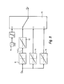
- the subsystem shown in Figure 11 is three Selections included between which over one Constant block 110 by means of a switching element 115 can be switched.
- the first choice comprises two series-connected characteristic curves 111 and 112.
- the block 111 makes the connection between the middle front wheel angle ⁇ _Fm and a hub Hub_I_d the rack 7 ago.
- the downstream block 112 contains theoretically present data of the rack 7. As a result there is a possibility, with a little effort others To implement rack translations.
- the second option contains in one Function block 113 which determined from the wheel alignment Relationship between middle front wheel angle ⁇ _Fm and Pinion angle ⁇ _G. This selection is more accurate than the first, but not so flexible to changes to the rack 7 customizable.
Landscapes
- Engineering & Computer Science (AREA)
- Chemical & Material Sciences (AREA)
- Combustion & Propulsion (AREA)
- Transportation (AREA)
- Mechanical Engineering (AREA)
- Physics & Mathematics (AREA)
- Mathematical Physics (AREA)
- Steering Control In Accordance With Driving Conditions (AREA)
Applications Claiming Priority (2)
| Application Number | Priority Date | Filing Date | Title |
|---|---|---|---|
| DE200410009815 DE102004009815A1 (de) | 2004-02-28 | 2004-02-28 | Lenksystem für ein Kraftfahrzeug und Verfahren zum Betrieb des Lenksystems |
| DE102004009815 | 2004-02-28 |
Publications (3)
| Publication Number | Publication Date |
|---|---|
| EP1568576A2 true EP1568576A2 (fr) | 2005-08-31 |
| EP1568576A3 EP1568576A3 (fr) | 2005-11-09 |
| EP1568576B1 EP1568576B1 (fr) | 2009-12-30 |
Family
ID=34745316
Family Applications (1)
| Application Number | Title | Priority Date | Filing Date |
|---|---|---|---|
| EP20050001538 Expired - Lifetime EP1568576B1 (fr) | 2004-02-28 | 2005-01-26 | Système de direction et procédé pour la commande du système de direction |
Country Status (2)
| Country | Link |
|---|---|
| EP (1) | EP1568576B1 (fr) |
| DE (2) | DE102004009815A1 (fr) |
Cited By (6)
| Publication number | Priority date | Publication date | Assignee | Title |
|---|---|---|---|---|
| WO2007071852A1 (fr) * | 2005-12-23 | 2007-06-28 | Renault S.A.S. | Procede et dispositif de commande de l'angle de braquage de roue arriere d'un vehicule automobile |
| FR2896753A1 (fr) * | 2006-01-27 | 2007-08-03 | Renault Sas | Procede et dispositif de compensation de variations de couple |
| WO2007134888A1 (fr) * | 2006-05-18 | 2007-11-29 | Zf Lenksysteme Gmbh | Système de direction pour véhicule |
| FR2930504A1 (fr) * | 2008-04-29 | 2009-10-30 | Renault Sas | Procede de fonctionnement d'un systeme de direction active d'un vehicule automobile. |
| WO2014199021A1 (fr) * | 2013-06-12 | 2014-12-18 | Université De Valenciennes Et Du Hainaut-Cambrésis | Système de direction pour véhicule |
| DE102019211455A1 (de) * | 2019-07-31 | 2021-02-04 | Volkswagen Aktiengesellschaft | Verfahren zur Steuerung eines Fahrzeugs |
Families Citing this family (10)
| Publication number | Priority date | Publication date | Assignee | Title |
|---|---|---|---|---|
| DE102005053459A1 (de) | 2005-11-04 | 2007-05-10 | Volkswagen Ag | Vorrichtung und Verfahren zum Filtern eines differenzierten Messsignals eines elektromechanischen Lenksystems |
| DE102006019732B4 (de) * | 2006-04-28 | 2019-03-14 | Bayerische Motoren Werke Aktiengesellschaft | Fahrzeug-Servolenksystem mit elektromotorischer Momentenunterstützung |
| DE102006030048A1 (de) * | 2006-06-29 | 2008-01-03 | Zf Lenksysteme Gmbh | Verfahren zur Erhöhung der Fahrstabilität eines Fahrzeugs |
| DE102006052092B4 (de) * | 2006-11-04 | 2021-01-07 | Robert Bosch Gmbh | Verfahren zum Betrieb eines Servolenksystems |
| US7634340B2 (en) | 2007-02-27 | 2009-12-15 | Gm Global Technology Operations, Inc. | Secure control mode transition methods for an active front steer system |
| DE102008012007B4 (de) * | 2008-03-01 | 2012-02-23 | Audi Ag | Verfahren zum Reduzieren einer Kipptendenz eines Kraftwagens und ein Lenksystem |
| DE102008041183B4 (de) * | 2008-08-12 | 2017-09-28 | Robert Bosch Automotive Steering Gmbh | Verfahren zum Betrieb eines elektronischen Servolenksystems eines Kraftfahrzeugs |
| DE102010003658B4 (de) | 2010-04-06 | 2014-03-06 | Bayerische Motoren Werke Aktiengesellschaft | Lenksystem eines Kraftfahrzeugs |
| DE102013011282B4 (de) * | 2013-07-05 | 2024-03-21 | Volkswagen Aktiengesellschaft | Verfahren und System zur Steuerung von Funktionen eines Fahrzeugs abhängig von einem Zustand einer Lenkwinkelerfassung sowie Fahrzeug |
| DE102019202406B3 (de) * | 2019-02-22 | 2020-04-16 | Robert Bosch Gmbh | Verfahren zum Betreiben eines mechanisch entkoppelten Lenksystems für ein Kraftfahrzeug |
Citations (1)
| Publication number | Priority date | Publication date | Assignee | Title |
|---|---|---|---|---|
| DE10013711A1 (de) | 2000-03-20 | 2001-10-11 | Bosch Gmbh Robert | Servounterstütztes Lenksystem eines Kraftfahrzeugs |
Family Cites Families (11)
| Publication number | Priority date | Publication date | Assignee | Title |
|---|---|---|---|---|
| DE4031316C2 (de) * | 1990-10-04 | 2001-11-22 | Bosch Gmbh Robert | Motorbetriebenes Servolenksystem |
| DE4140239A1 (de) * | 1991-12-06 | 1993-06-09 | Robert Bosch Gmbh, 7000 Stuttgart, De | Verfahren und vorrichtung zur erzeugung eines fuer die querbewegung eines fahrzeugs repraesentativen signals |
| DE19618624C1 (de) * | 1996-05-09 | 1997-09-25 | Daimler Benz Ag | Vorrichtung zur Auswertung von Signalen |
| US6226579B1 (en) * | 1997-03-22 | 2001-05-01 | Robert Bosch Gmbh | Method and apparatus for operating a steering system for a motor vehicle |
| DE10012133A1 (de) * | 2000-03-13 | 2001-09-27 | Bosch Gmbh Robert | Überwachungssystem zur Überwachung einer Stelleinrichtung im Kraftfahrzeug |
| AUPR114800A0 (en) * | 2000-11-01 | 2000-11-23 | Bishop Steering Technology Limited | Variable ratio steering gear |
| JP3970094B2 (ja) * | 2002-05-27 | 2007-09-05 | 株式会社ジェイテクト | 操舵装置 |
| DE10328752A1 (de) * | 2002-07-05 | 2004-02-05 | Continental Teves Ag & Co. Ohg | Verfahren zum Lenken eines Fahrzeugs mit einer Überlagerungslenkung |
| JP3757910B2 (ja) * | 2002-07-09 | 2006-03-22 | トヨタ自動車株式会社 | 車両用操舵制御装置 |
| DE10325484A1 (de) * | 2002-09-06 | 2004-03-25 | Continental Teves Ag & Co. Ohg | Verfahren zum Lenken eines Fahrzeugs mit einer Überlagerungslenkung |
| DE10247975B4 (de) * | 2002-10-15 | 2014-03-27 | Robert Bosch Gmbh | Verfahren zum Betreiben einer Lenkung, ein Computerprogramm, ein Steuergerät sowie eine Lenkung für ein Fahrzeug |
-
2004
- 2004-02-28 DE DE200410009815 patent/DE102004009815A1/de not_active Withdrawn
-
2005
- 2005-01-26 EP EP20050001538 patent/EP1568576B1/fr not_active Expired - Lifetime
- 2005-01-26 DE DE200550008760 patent/DE502005008760D1/de not_active Expired - Lifetime
Patent Citations (1)
| Publication number | Priority date | Publication date | Assignee | Title |
|---|---|---|---|---|
| DE10013711A1 (de) | 2000-03-20 | 2001-10-11 | Bosch Gmbh Robert | Servounterstütztes Lenksystem eines Kraftfahrzeugs |
Cited By (10)
| Publication number | Priority date | Publication date | Assignee | Title |
|---|---|---|---|---|
| WO2007071852A1 (fr) * | 2005-12-23 | 2007-06-28 | Renault S.A.S. | Procede et dispositif de commande de l'angle de braquage de roue arriere d'un vehicule automobile |
| FR2895347A1 (fr) * | 2005-12-23 | 2007-06-29 | Renault Sas | Procede et dispositif de commande de l'angle de braquage de roue arriere d'un vehicule automobile |
| CN101346270B (zh) * | 2005-12-23 | 2011-09-14 | 雷诺股份公司 | 用于控制机动车辆后轮的转向角的方法和设备 |
| FR2896753A1 (fr) * | 2006-01-27 | 2007-08-03 | Renault Sas | Procede et dispositif de compensation de variations de couple |
| WO2007134888A1 (fr) * | 2006-05-18 | 2007-11-29 | Zf Lenksysteme Gmbh | Système de direction pour véhicule |
| FR2930504A1 (fr) * | 2008-04-29 | 2009-10-30 | Renault Sas | Procede de fonctionnement d'un systeme de direction active d'un vehicule automobile. |
| EP2113442A1 (fr) * | 2008-04-29 | 2009-11-04 | Renault s.a.s. | Procédé de fonctionnement d'un système de direction active d'un véhicule automobile |
| WO2014199021A1 (fr) * | 2013-06-12 | 2014-12-18 | Université De Valenciennes Et Du Hainaut-Cambrésis | Système de direction pour véhicule |
| DE102019211455A1 (de) * | 2019-07-31 | 2021-02-04 | Volkswagen Aktiengesellschaft | Verfahren zur Steuerung eines Fahrzeugs |
| DE102019211455B4 (de) | 2019-07-31 | 2021-08-26 | Volkswagen Aktiengesellschaft | Verfahren zur Steuerung eines Fahrzeugs |
Also Published As
| Publication number | Publication date |
|---|---|
| DE502005008760D1 (de) | 2010-02-11 |
| DE102004009815A1 (de) | 2005-09-15 |
| EP1568576A3 (fr) | 2005-11-09 |
| EP1568576B1 (fr) | 2009-12-30 |
Similar Documents
| Publication | Publication Date | Title |
|---|---|---|
| DE112004002252B4 (de) | Verfahren zum Unterstützen eines Fahrzeugbedieners beim Stabilisieren eines Fahrzeugs | |
| DE10354662B4 (de) | Verfahren und Vorrichtung zum Unterstützen des Fahrers eines Kraftfahrzeugs in fahrdynamischen Grenzsituationen | |
| EP1521695B1 (fr) | Procede pour accroitre la stabilite d'un vehicule | |
| EP2013069B1 (fr) | Procédé et dispositif de détermination d'un angle de braquage optimal lors de situations de sous-virage d'un véhicule | |
| EP1568576B1 (fr) | Système de direction et procédé pour la commande du système de direction | |
| DE60311566T2 (de) | Fahrzeugbremssystem und Verfahren zu dessen Regelung | |
| DE3545715C2 (fr) | ||
| DE69615239T2 (de) | Verfahren zur Steuerung des Gierens eines Kraftfahrzeuges | |
| DE3518221C2 (fr) | ||
| DE69607553T2 (de) | Regelsystem für das Verhalten von Kraftfahrzeugen, basierend auf der Beobachtung der Bewegung der Hinterräder | |
| DE19809192B4 (de) | Abdriftsteuervorrichtung | |
| DE19856790A1 (de) | Integriertes Steuersystem für ein Fahrzeug | |
| DE112013006493T5 (de) | Fahrzeugsteuereinrichtung | |
| DE19926745A1 (de) | Hindernis-Ausweich-Steuerungssystem für ein Fahrzeug | |
| DE19856792A1 (de) | Integriertes Steuersystem für ein Fahrzeug | |
| WO2014086646A1 (fr) | Procédé de régulation de la dynamique de conduite | |
| WO2005063538A1 (fr) | Procede pour reguler une pression de freinage sur des voies de circulation entrainant des coefficients d'adherence non homogenes | |
| DE102005018069B4 (de) | Steuerung für aktive Radlenkung | |
| DE19632068B4 (de) | Vorrichtung zur Regelung der Fahrstabilität eines Fahrzeugs | |
| DE102006050215A1 (de) | Verfahren und Vorrichtung zum Stabilisieren eines Kraftfahrzeugs | |
| EP0859712B1 (fr) | Procede et dispositif de regulation d'une quantite de mouvement representant le mouvement du vehicule | |
| EP1799484B1 (fr) | Procede et dispositif pour regler le degre de verrouillage d'un systeme de verrouillage de differentiel a commande electronique | |
| EP1568577A2 (fr) | Système de direction pour un véhicule et procédé pour le commande d'un tel système de direction | |
| DE102009008107B4 (de) | Verfahren zur Bestimmung einer Regelgröße einer koordinierten Steuerung auf einer Split-Fahrbahnoberfläche unter Verwendung einer Verzögerung eines Fahrzeugs | |
| EP1802481B1 (fr) | Procede et dispositif pour commander le degre de blocage d'un systeme de blocage de differentiel a commande electronique |
Legal Events
| Date | Code | Title | Description |
|---|---|---|---|
| PUAI | Public reference made under article 153(3) epc to a published international application that has entered the european phase |
Free format text: ORIGINAL CODE: 0009012 |
|
| AK | Designated contracting states |
Kind code of ref document: A2 Designated state(s): AT BE BG CH CY CZ DE DK EE ES FI FR GB GR HU IE IS IT LI LT LU MC NL PL PT RO SE SI SK TR |
|
| AX | Request for extension of the european patent |
Extension state: AL BA HR LV MK YU |
|
| PUAL | Search report despatched |
Free format text: ORIGINAL CODE: 0009013 |
|
| AK | Designated contracting states |
Kind code of ref document: A3 Designated state(s): AT BE BG CH CY CZ DE DK EE ES FI FR GB GR HU IE IS IT LI LT LU MC NL PL PT RO SE SI SK TR |
|
| AX | Request for extension of the european patent |
Extension state: AL BA HR LV MK YU |
|
| AKX | Designation fees paid |
Designated state(s): DE FR GB IT SE |
|
| 17P | Request for examination filed |
Effective date: 20060206 |
|
| 17Q | First examination report despatched |
Effective date: 20060814 |
|
| GRAP | Despatch of communication of intention to grant a patent |
Free format text: ORIGINAL CODE: EPIDOSNIGR1 |
|
| RIC1 | Information provided on ipc code assigned before grant |
Ipc: B62D 5/00 20060101ALI20070711BHEP Ipc: B62D 6/00 20060101AFI20070711BHEP |
|
| GRAS | Grant fee paid |
Free format text: ORIGINAL CODE: EPIDOSNIGR3 |
|
| GRAA | (expected) grant |
Free format text: ORIGINAL CODE: 0009210 |
|
| AK | Designated contracting states |
Kind code of ref document: B1 Designated state(s): DE FR GB IT SE |
|
| REG | Reference to a national code |
Ref country code: GB Ref legal event code: FG4D Free format text: NOT ENGLISH |
|
| REF | Corresponds to: |
Ref document number: 502005008760 Country of ref document: DE Date of ref document: 20100211 Kind code of ref document: P |
|
| REG | Reference to a national code |
Ref country code: SE Ref legal event code: TRGR |
|
| PLBE | No opposition filed within time limit |
Free format text: ORIGINAL CODE: 0009261 |
|
| STAA | Information on the status of an ep patent application or granted ep patent |
Free format text: STATUS: NO OPPOSITION FILED WITHIN TIME LIMIT |
|
| 26N | No opposition filed |
Effective date: 20101001 |
|
| PGFP | Annual fee paid to national office [announced via postgrant information from national office to epo] |
Ref country code: SE Payment date: 20110111 Year of fee payment: 7 |
|
| PGFP | Annual fee paid to national office [announced via postgrant information from national office to epo] |
Ref country code: IT Payment date: 20120116 Year of fee payment: 8 |
|
| REG | Reference to a national code |
Ref country code: SE Ref legal event code: EUG |
|
| PG25 | Lapsed in a contracting state [announced via postgrant information from national office to epo] |
Ref country code: SE Free format text: LAPSE BECAUSE OF NON-PAYMENT OF DUE FEES Effective date: 20120127 |
|
| PGFP | Annual fee paid to national office [announced via postgrant information from national office to epo] |
Ref country code: FR Payment date: 20130204 Year of fee payment: 9 Ref country code: GB Payment date: 20130123 Year of fee payment: 9 |
|
| PG25 | Lapsed in a contracting state [announced via postgrant information from national office to epo] |
Ref country code: IT Free format text: LAPSE BECAUSE OF NON-PAYMENT OF DUE FEES Effective date: 20130126 |
|
| GBPC | Gb: european patent ceased through non-payment of renewal fee |
Effective date: 20140126 |
|
| REG | Reference to a national code |
Ref country code: FR Ref legal event code: ST Effective date: 20140930 |
|
| PG25 | Lapsed in a contracting state [announced via postgrant information from national office to epo] |
Ref country code: FR Free format text: LAPSE BECAUSE OF NON-PAYMENT OF DUE FEES Effective date: 20140131 Ref country code: GB Free format text: LAPSE BECAUSE OF NON-PAYMENT OF DUE FEES Effective date: 20140126 |
|
| REG | Reference to a national code |
Ref country code: DE Ref legal event code: R081 Ref document number: 502005008760 Country of ref document: DE Owner name: ROBERT BOSCH AUTOMOTIVE STEERING GMBH, DE Free format text: FORMER OWNER: ZF LENKSYSTEME GMBH, 73527 SCHWAEBISCH GMUEND, DE Effective date: 20150423 |
|
| REG | Reference to a national code |
Ref country code: DE Ref legal event code: R084 Ref document number: 502005008760 Country of ref document: DE |
|
| REG | Reference to a national code |
Ref country code: DE Ref legal event code: R081 Ref document number: 502005008760 Country of ref document: DE Owner name: ROBERT BOSCH GMBH, DE Free format text: FORMER OWNER: ROBERT BOSCH AUTOMOTIVE STEERING GMBH, 73527 SCHWAEBISCH GMUEND, DE |
|
| PGFP | Annual fee paid to national office [announced via postgrant information from national office to epo] |
Ref country code: DE Payment date: 20220324 Year of fee payment: 18 |
|
| REG | Reference to a national code |
Ref country code: DE Ref legal event code: R119 Ref document number: 502005008760 Country of ref document: DE |
|
| PG25 | Lapsed in a contracting state [announced via postgrant information from national office to epo] |
Ref country code: DE Free format text: LAPSE BECAUSE OF NON-PAYMENT OF DUE FEES Effective date: 20230801 |