EP1568821A2 - System und Verfahren zum Herstellen eines schotterlosen Gleisoberbaus - Google Patents
System und Verfahren zum Herstellen eines schotterlosen Gleisoberbaus Download PDFInfo
- Publication number
- EP1568821A2 EP1568821A2 EP05001314A EP05001314A EP1568821A2 EP 1568821 A2 EP1568821 A2 EP 1568821A2 EP 05001314 A EP05001314 A EP 05001314A EP 05001314 A EP05001314 A EP 05001314A EP 1568821 A2 EP1568821 A2 EP 1568821A2
- Authority
- EP
- European Patent Office
- Prior art keywords
- rail
- concrete
- slab
- ballast
- constructed
- Prior art date
- Legal status (The legal status is an assumption and is not a legal conclusion. Google has not performed a legal analysis and makes no representation as to the accuracy of the status listed.)
- Granted
Links
Images


Classifications
-
- D—TEXTILES; PAPER
- D05—SEWING; EMBROIDERING; TUFTING
- D05C—EMBROIDERING; TUFTING
- D05C3/00—General types of embroidering machines
- D05C3/02—General types of embroidering machines with vertical needles
-
- E—FIXED CONSTRUCTIONS
- E01—CONSTRUCTION OF ROADS, RAILWAYS, OR BRIDGES
- E01B—PERMANENT WAY; PERMANENT-WAY TOOLS; MACHINES FOR MAKING RAILWAYS OF ALL KINDS
- E01B1/00—Ballastway; Other means for supporting the sleepers or the track; Drainage of the ballastway
- E01B1/002—Ballastless track, e.g. concrete slab trackway, or with asphalt layers
- E01B1/004—Ballastless track, e.g. concrete slab trackway, or with asphalt layers with prefabricated elements embedded in fresh concrete or asphalt
-
- D—TEXTILES; PAPER
- D05—SEWING; EMBROIDERING; TUFTING
- D05C—EMBROIDERING; TUFTING
- D05C13/00—Auxiliary devices incorporated in embroidering machines, not otherwise provided for; Ancillary apparatus for use with embroidering machines
-
- E—FIXED CONSTRUCTIONS
- E01—CONSTRUCTION OF ROADS, RAILWAYS, OR BRIDGES
- E01B—PERMANENT WAY; PERMANENT-WAY TOOLS; MACHINES FOR MAKING RAILWAYS OF ALL KINDS
- E01B1/00—Ballastway; Other means for supporting the sleepers or the track; Drainage of the ballastway
- E01B1/002—Ballastless track, e.g. concrete slab trackway, or with asphalt layers
- E01B1/007—Ballastless track, e.g. concrete slab trackway, or with asphalt layers with interlocking means to withstand horizontal forces
-
- E—FIXED CONSTRUCTIONS
- E01—CONSTRUCTION OF ROADS, RAILWAYS, OR BRIDGES
- E01B—PERMANENT WAY; PERMANENT-WAY TOOLS; MACHINES FOR MAKING RAILWAYS OF ALL KINDS
- E01B2204/00—Characteristics of the track and its foundations
- E01B2204/06—Height or lateral adjustment means or positioning means for slabs, sleepers or rails
Definitions
- the present invention relates to a railroad concrete ballast construction system and method capable of exchanging a certain section of a gravel ballast track with a new concrete ballast track even when a train currently runs on a railroad, and in particular to a railroad concrete ballast construction system and method capable of constructing a concrete ballast at a certain section of a gravel ballast having no gravel and rail tie for exchanging a certain section of a gravel ballast with a new concrete ballast in a state that a train currently runs on a railroad, curing and disassembling a structure adapted to fix a rail for a stable operation of a train for thereby effectively finishing an exchanging work.
- the ballast has been used for widely distributing a weight transferred through a rail and rail tie, and transferring to a ground, resulting in a reduction of the weight.
- the ballast is capable of preventing a rail tie movement occurring due to a contraction and elongation of a rail by a temperature change based on a ballast resistance force for thereby absorbing a vibration of a train and enhancing an absorbing effect.
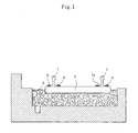
- the gravel ballast includes a rail 1 that supports train wheels, a rail tie 2 that is formed of a concrete rail tie or a wooden rail tie for transferring a weight or impact from the rail 1 to the ground when a train runs on a rail road, a gravel ballast 3 that is provided between the ground and the rail tie 2 for thereby absorbing the weight transferred thereto, and a clamp 5 of which one end is engaged with a fixture 4 fixed at the rail tie 2, an intermediate portion supports a flange 1 a of the rail 1, and the other end supports the fixture 4 wherein the clamp 5 is designed with three support points in an E-shape.
- the above gravel ballast has an advantage of uniformly distributing the weight transferred through the rail 1 when the train runs to the ground.
- the gravels of the gravel ballast 3 may be broken and worn away, thus producing small gravel pieces.
- the function of the ballast is significantly decreased and the safety factor of the train operation is decreased, thereby causing an accident.
- a railroad concrete ballast construction system comprising a concrete rail tie slab in which a mounting part formed at both sides is engaged at a certain section having no gravel and rail tie on a gravel ballast track by a certain fixture; a rail support unit that is detachably installed between opposite slabs, and supports a vertical weight applied to a rail when a train runs, and supports the rail on the ground for thereby preventing the rail from being sagged; a gauge tie rod of which both ends are fixed at a rail support upper plate and an intermediate portion is flexible, for thereby preventing an elongation of the rail when a concrete of the slab is constructed; a gauge strut of which both ends are fixed at an inner surface of a body of the rail and an intermediate portion is flexible, for thereby preventing a contraction of the rail when a concrete of the slab is constructed; a horizontal support member that is installed outside the rail to be on the same line as the gauge strut, and supports an outer surface of the body of the rail and maintains
- receiving groove is formed at an outer surface of the slab so that the rail support unit is disassembled from the slab and is pulled out in an outer direction after the concrete is cured.
- the concrete rail tie slab includes a mounting part that is protruded from the left and right sides of an upper surface of the slab in opposite directions wherein the rail is mounted thereon; an engaging part that is engaged with an engaging hole formed at the left and right sides of the mounting part and has a certain elastic force capable of supporting a flange of the inner and outer sides of the rail; and an assistant engaging part that is engaged with a through hole formed at the slab in an outer direction of the mounting part and is embedded when a concrete is constructed for thereby enhancing an engaging force of the slab.
- the concrete rail tie slab is formed of a steel-reinforced concrete structure of which a tensional force is reinforced using steel bars embedded.
- a railroad rail concrete ballast construction method comprising the steps of removing gravels and rail ties from the ground and the rail in a certain section of a gravel ballast track; engaging a concrete rail tie slab at a lower side of a flange of the rail using a certain fixture; supporting the rail on the ground using a rail support unit installed between the opposite slabs for thereby preventing a sagging of the rail by supporting a vertical weight applied to the rail when a trains runs on the railroad; preventing an elongation of the rail using a gauge tie rod of which both ends are fixed at a rail support upper plate, when a concrete is constructed; preventing a contraction of the rail using a gauge strut of which both ends are fixed at an inner surface of a body of the rail, when a concrete of the slab is constructed; maintaining a horizontal state of the rail, when a concrete of the slab is constructed, by a horizontal support member installed outside the rail to be the same line as the gauge strut; fixing the slab on the ground
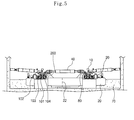
- a railroad concrete ballast construction system includes a concrete rail tie slab 20 in which a mounting unit 21 is engaged at a rail 10 by a certain fixture in a certain section of a gravel ballast track having no gravel and rail tie wherein a train can run on a railroad; and a rail support unit 30 that is installed so that it is disassembled between the opposite slabs 20 and is designed to support a vertical weight applied to the rail 10 when the train runs and the weight of the rail 10 at the ground for thereby preventing the rail 10 from being sagged.
- the rail support unit 30 may be preferably formed of a hydraulic jack, a screw jack, a rack jack, etc.
- the concrete rail tie slab 20 may be preferably formed of a reinforced concrete (RC) of which a tensional force is reinforced by an embedded reinforcing bar (not shown).
- RC reinforced concrete
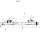
- a horizontal support member 60 that is installed outside the rail 10 to be on the same line with the gauge strut 50 and supports an outer side of the body 11 of the rail 10 for thereby maintaining a horizontal state of the rail when the concrete of the slab 20 is constructed; and a concrete ballast 70 that fixes the slab 20 on the ground based on the concrete constructed between the ground and the slab 20 through an inlet 22 formed at the slab 20.
- the concrete rail tie slab 20 includes a mounting part 21 that is protruded from the left and right sides of the upper surface of the slab 20 in opposite directions wherein the rail 10 is mounted thereon; an engaging part 25 that is engaged to an engaging hole 24 formed at the left and right sides of the mounting part 21 and has an elastic force and is fixed by an engaging bolt B supporting a flange 12 at the inner and outer sides of the rail 10; and an assistant engaging part 27 that is engaged with a through hole 26 formed at the slab 20 at the outer side of the mounting part 21 for thereby enhancing an engaging force of the slab 20 when the concrete is constructed.
- a receiving groove 23 is formed at an outer surface of the slab 20 so that the rail support part 30 is disassembled from the slab 20 in an outer direction after the concrete is cured.
- reference numeral 90 represents an anti-vibration member that is installed at the lower side of the flange 20 of the rail 10 for thereby absorbing impacts and vibrations
- 100 represents a driving motor for driving a pair of levers 103 and 104 when a driving shaft 102 is rotated for thereby preventing the rail 10 from being sagged by a support part 101.
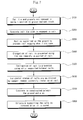
- the gravels and rail ties are removed from the ground and the rail 10 in a certain section of the gravel ballast track on which the train can run in a step S100.
- the rail 10 in the section having no gravel and rail tie is installed with a certain gap from the ground.
- the concrete rail tie slab 20 is engaged to a lower side of the flange 12 of the rail 10 using a certain fixture in a step S200.
- the slab 20 is moved by a certain lifting equipment such as a crane, etc. and is inserted between the rail 10 and the ground.
- the rail 10 On the ground, the rail 10 is supported by the rail support unit 30 installed between the opposite slabs 20 for thereby preventing the rail 10 from being sagged by supporting a vertical weight applied to the rail 10 when the train runs during a working time in a step S300.
- the rail support unit 30 may be formed of a hydraulic jack, a screw jack, etc.
- the method for driving the rail support unit 30 and supporting the rail 10 is a known art, so that the detailed description thereon will be omitted.
- a mold 200 is installed around the rail support unit 30 for thereby preventing the concrete from being inputted into the surrounding portions of the rail support unit 30 when constructing the concrete.
- the portions corresponding to the mold 200 is finished with cement after the concrete is cured.
- the gauge tie rod 40 of which both ends are fixedly supported by the rail support upper plate 80 and an intermediate part is flexible is adapted to prevent the rail 10 from being elongated when the concrete of the slab 20 is constructed in a step S400.
- the gauge strut 50 of which both ends are fixedly supported by the rail support upper plate 80 and an intermediate portion is flexible is adapted to prevent the rail 10 from being sagged when the concrete is constructed in a step S500.
- the horizontal support member 60 that is installed outside the rail 10 to be at the same line with the gauge strut 50 wherein an intermediate portion of the same is flexible is adapted to maintain a horizontal state of the rail 10 when the concrete of the slab 20 is constructed in a step S600.
- the concrete supplied between the ground and the slab 20 through the inlet 22 formed at the center of the slab 20 constructs the slab 20 on the ground in a step S700. At this time, the concrete is constructed with a certain height including the height of the slab 20 for thereby enhancing a support force.
- the rail support unit 30, the gauge tie rod 40, the gauge strut 50 and the horizontal support member 60 are disassembled from the rail 10 after the concrete ballast 70 is cured (generally after 3 ⁇ 5 days) in a step S800.
- the rail 10 is supported by a plurality of the rail support part 30 in a state that the rail tie and gravel are removed from the lower side of the rail 10, it is possible to prevent the rail 10 from being sagged wherein the rail 10 is sagged due to a vertical weight from the rail 10 when the train runs.
- the slab 20 is designed to prevent the rail 10 from being sagged by the tie rod 40 when the concrete is constructed, and the strut 50 is designed to prevent the rail 10 from being contracted, and the horizontal support member 60 is designed to maintain a horizontal state of the rail.
- the railroad concrete ballast construction system according to the present invention has the following advantages.
- the gravel ballast can be exchanged with a concrete ballast during the operation of the train, any inconvenience is not provided to train passenger.
- the work for exchanging the gravel ballast with a concrete ballast can be performed during a day time, resulting in a better work environment. Therefore, work time is significantly decreased, and workers have less workload.
Landscapes
- Engineering & Computer Science (AREA)
- Textile Engineering (AREA)
- Architecture (AREA)
- Civil Engineering (AREA)
- Structural Engineering (AREA)
- Machines For Laying And Maintaining Railways (AREA)
- Train Traffic Observation, Control, And Security (AREA)
- Railway Tracks (AREA)
Applications Claiming Priority (2)
| Application Number | Priority Date | Filing Date | Title |
|---|---|---|---|
| KR1020040012205A KR100595429B1 (ko) | 2004-02-24 | 2004-02-24 | 철도 레일 콘크리트도상 궤도구조 및 그 시공방법 |
| KR2004012205 | 2004-02-24 |
Publications (3)
| Publication Number | Publication Date |
|---|---|
| EP1568821A2 true EP1568821A2 (de) | 2005-08-31 |
| EP1568821A3 EP1568821A3 (de) | 2006-11-02 |
| EP1568821B1 EP1568821B1 (de) | 2008-03-19 |
Family
ID=34747934
Family Applications (1)
| Application Number | Title | Priority Date | Filing Date |
|---|---|---|---|
| EP05001314A Expired - Lifetime EP1568821B1 (de) | 2004-02-24 | 2005-01-24 | System und Verfahren zum Herstellen eines schotterlosen Gleisoberbaus |
Country Status (4)
| Country | Link |
|---|---|
| EP (1) | EP1568821B1 (de) |
| KR (1) | KR100595429B1 (de) |
| AT (1) | ATE389747T1 (de) |
| DE (1) | DE602005005372T2 (de) |
Cited By (2)
| Publication number | Priority date | Publication date | Assignee | Title |
|---|---|---|---|---|
| EP2206831A3 (de) * | 2009-01-13 | 2012-03-28 | GSG Knape Gleissanierung GmbH | Vorrichtung zum Heben und Richten von Gleisen |
| CN116122083A (zh) * | 2023-01-10 | 2023-05-16 | 武汉理工大学 | 全支撑承轨台及无砟轨道、支撑组件 |
Families Citing this family (7)
| Publication number | Priority date | Publication date | Assignee | Title |
|---|---|---|---|---|
| KR100744175B1 (ko) * | 2005-12-07 | 2007-08-02 | 한국철도기술연구원 | 자갈 도상 궤도에서의 프리캐스트 콘크리트 슬래브와 그를이용한 콘크리트 도상 부설장치 및 부설방법 |
| KR101052906B1 (ko) * | 2010-12-02 | 2011-07-29 | 삼표이앤씨 주식회사 | 프리캐스트 슬래브 궤도 시스템 및 프리캐스트 슬래브 궤도 시스템 시공 방법. |
| KR101439527B1 (ko) * | 2012-08-20 | 2014-09-15 | 영중산업 주식회사 | 콘크리트도상의 궤광 설치용 레일지지대 |
| CN103334350B (zh) * | 2013-07-16 | 2015-08-12 | 中国铁道科学研究院铁道建筑研究所 | 一种预应力混凝土轨枕、轨道板用搓丝定尺螺旋肋钢丝 |
| KR101660212B1 (ko) | 2016-06-15 | 2016-10-10 | 이국현 | 철도 레일 설치 모듈 조립 방법 |
| KR102091735B1 (ko) | 2018-03-05 | 2020-03-20 | 한국철도기술연구원 | 수직변형 및 수평변형의 저항성능을 향상시킨 급속경화궤도 및 그 시공방법 |
| KR102196373B1 (ko) | 2020-04-07 | 2020-12-29 | 황윤태 | 프리캐스트 슬래브 패널을 이용한 철도궤도 시공방법 |
Family Cites Families (6)
| Publication number | Priority date | Publication date | Assignee | Title |
|---|---|---|---|---|
| FR2691484B1 (fr) * | 1992-05-22 | 1994-07-29 | Vanotti Gerard | Procede de construction d'une voie ferree dans du beton. |
| DE4437826A1 (de) * | 1993-10-18 | 1996-04-18 | Betonwerk Rethwisch Gmbh | Schotterloser Oberbau |
| DE19903702A1 (de) * | 1999-01-30 | 2000-08-03 | Bahnbau Wels Gmbh Wels | Vorrichtung zur Höhen- und Seitenausrichtung und/oder -abstützung der Schienen eines Gleises |
| DK1026320T3 (da) * | 1999-02-08 | 2004-03-29 | Hochtief Ag Hoch Tiefbauten | Fremgangsmåde til fremstilling af et sporanlæg uden ballast |
| KR20030065897A (ko) * | 2002-02-01 | 2003-08-09 | 주식회사 에이브이티 | 콘크리트도상 궤도의 구조 및 그 시공방법 |
| KR100446310B1 (ko) * | 2002-11-07 | 2004-08-30 | (주)신성엔지니어링 | 철도 궤도의 횡방향 이동 방지장치 |
-
2004
- 2004-02-24 KR KR1020040012205A patent/KR100595429B1/ko not_active Expired - Lifetime
-
2005
- 2005-01-24 DE DE602005005372T patent/DE602005005372T2/de not_active Expired - Lifetime
- 2005-01-24 AT AT05001314T patent/ATE389747T1/de not_active IP Right Cessation
- 2005-01-24 EP EP05001314A patent/EP1568821B1/de not_active Expired - Lifetime
Cited By (2)
| Publication number | Priority date | Publication date | Assignee | Title |
|---|---|---|---|---|
| EP2206831A3 (de) * | 2009-01-13 | 2012-03-28 | GSG Knape Gleissanierung GmbH | Vorrichtung zum Heben und Richten von Gleisen |
| CN116122083A (zh) * | 2023-01-10 | 2023-05-16 | 武汉理工大学 | 全支撑承轨台及无砟轨道、支撑组件 |
Also Published As
| Publication number | Publication date |
|---|---|
| EP1568821A3 (de) | 2006-11-02 |
| ATE389747T1 (de) | 2008-04-15 |
| DE602005005372T2 (de) | 2008-07-17 |
| KR20050087018A (ko) | 2005-08-31 |
| KR100595429B1 (ko) | 2006-07-03 |
| DE602005005372D1 (de) | 2008-04-30 |
| EP1568821B1 (de) | 2008-03-19 |
Similar Documents
| Publication | Publication Date | Title |
|---|---|---|
| JP5266291B2 (ja) | 橋梁床版の施工方法とプレキャスト床版の継手構造 | |
| CN100570057C (zh) | 用钢筋混凝土预制板制造板块组合结构 | |
| KR100454405B1 (ko) | 철도교의 강교를 콘크리트교로 치환시켜 유도상화하는공법 | |
| JP6074378B2 (ja) | 伸縮装置の取替え方法と仮設覆工版構造 | |
| JP6837343B2 (ja) | 合成桁の床版取替工法 | |
| CN105525541A (zh) | 轨道交通用新型预制板式减振轨道结构 | |
| EP1568821B1 (de) | System und Verfahren zum Herstellen eines schotterlosen Gleisoberbaus | |
| JP4934779B2 (ja) | 乗降場構成体および乗降場設置方法 | |
| KR100891961B1 (ko) | 가설구조물을 이용하여 도로 또는 철도의 노후된 교량이나 무도상 교량을 유도상화 하기 위한 교량 교체공법 및 그 장치 | |
| KR100355091B1 (ko) | 조립식 브라켓을 이용한 교량의 내하력 보강방법 | |
| KR100775053B1 (ko) | 기존 강교거더를 활용한 제자리 타설 콘크리트 유도상화공법 및 그 구조 | |
| JP2002227101A (ja) | 鉄道線路用マクラギ一体型コンクリート道床構造 | |
| KR100454406B1 (ko) | 가벤트를 이용하여 철도교의 강교를 콘크리트교로치환하여 유도상화하는 공법 및 그 장치 | |
| KR20050108867A (ko) | 철도교량의 상부구조물 교체 및 이를 이용한 유도상화방법. | |
| KR20130009391A (ko) | 철도 궤도용 콘크리트 블록의 제조방법 및 이 방법에 의해 제조된 콘크리트 블록을 이용한 철도 궤도 부설방법 | |
| KR100841685B1 (ko) | 철도교용 거더와 그 제조방법, 그리고 그의 시공 방법 | |
| KR20040086653A (ko) | 일체식 복합교대 교량 및 그 시공방법 | |
| KR20090070852A (ko) | 보차도 경계석 시공방법 및 장치 | |
| KR100603901B1 (ko) | 기존 거더의 일부를 활용한 판형교 유도상 구조 및 시공방법 | |
| KR101756965B1 (ko) | 유지 보수가 가능한 높낮이 조절형 철도궤도선로 시공방법 및 이를 이용한 철도궤도선로 보수방법 | |
| KR102161168B1 (ko) | 교량 가설용 결합형 멀티 트랜스포터 및 이를 이용한 교량 가설 공법 | |
| CN210151571U (zh) | 预制护栏安装定位装置 | |
| KR101996601B1 (ko) | 도상 개량용 모노블럭 및 그의 시공방법 | |
| CN116427217B (zh) | 一种用于安装轨道伸缩装置和钢轨伸缩调节器的安装方法 | |
| CN119221396B (zh) | 一种采用预制站台板的悬挑式站台及其施工方法 |
Legal Events
| Date | Code | Title | Description |
|---|---|---|---|
| PUAI | Public reference made under article 153(3) epc to a published international application that has entered the european phase |
Free format text: ORIGINAL CODE: 0009012 |
|
| 17P | Request for examination filed |
Effective date: 20050124 |
|
| AK | Designated contracting states |
Kind code of ref document: A2 Designated state(s): AT BE BG CH CY CZ DE DK EE ES FI FR GB GR HU IE IS IT LI LT LU MC NL PL PT RO SE SI SK TR |
|
| AX | Request for extension of the european patent |
Extension state: AL BA HR LV MK YU |
|
| RAP1 | Party data changed (applicant data changed or rights of an application transferred) |
Owner name: SEOUL METRO |
|
| PUAL | Search report despatched |
Free format text: ORIGINAL CODE: 0009013 |
|
| AK | Designated contracting states |
Kind code of ref document: A3 Designated state(s): AT BE BG CH CY CZ DE DK EE ES FI FR GB GR HU IE IS IT LI LT LU MC NL PL PT RO SE SI SK TR |
|
| AX | Request for extension of the european patent |
Extension state: AL BA HR LV MK YU |
|
| AKX | Designation fees paid |
Designated state(s): AT BE BG CH CY CZ DE DK EE ES FI FR GB GR HU IE IS IT LI LT LU MC NL PL PT RO SE SI SK TR |
|
| GRAP | Despatch of communication of intention to grant a patent |
Free format text: ORIGINAL CODE: EPIDOSNIGR1 |
|
| GRAS | Grant fee paid |
Free format text: ORIGINAL CODE: EPIDOSNIGR3 |
|
| GRAA | (expected) grant |
Free format text: ORIGINAL CODE: 0009210 |
|
| AK | Designated contracting states |
Kind code of ref document: B1 Designated state(s): AT BE BG CH CY CZ DE DK EE ES FI FR GB GR HU IE IS IT LI LT LU MC NL PL PT RO SE SI SK TR |
|
| REG | Reference to a national code |
Ref country code: GB Ref legal event code: FG4D |
|
| REG | Reference to a national code |
Ref country code: CH Ref legal event code: EP |
|
| REF | Corresponds to: |
Ref document number: 602005005372 Country of ref document: DE Date of ref document: 20080430 Kind code of ref document: P |
|
| REG | Reference to a national code |
Ref country code: IE Ref legal event code: FG4D |
|
| PG25 | Lapsed in a contracting state [announced via postgrant information from national office to epo] |
Ref country code: LT Free format text: LAPSE BECAUSE OF FAILURE TO SUBMIT A TRANSLATION OF THE DESCRIPTION OR TO PAY THE FEE WITHIN THE PRESCRIBED TIME-LIMIT Effective date: 20080319 Ref country code: FI Free format text: LAPSE BECAUSE OF FAILURE TO SUBMIT A TRANSLATION OF THE DESCRIPTION OR TO PAY THE FEE WITHIN THE PRESCRIBED TIME-LIMIT Effective date: 20080319 |
|
| PG25 | Lapsed in a contracting state [announced via postgrant information from national office to epo] |
Ref country code: AT Free format text: LAPSE BECAUSE OF FAILURE TO SUBMIT A TRANSLATION OF THE DESCRIPTION OR TO PAY THE FEE WITHIN THE PRESCRIBED TIME-LIMIT Effective date: 20080319 |
|
| NLV1 | Nl: lapsed or annulled due to failure to fulfill the requirements of art. 29p and 29m of the patents act | ||
| PG25 | Lapsed in a contracting state [announced via postgrant information from national office to epo] |
Ref country code: SI Free format text: LAPSE BECAUSE OF FAILURE TO SUBMIT A TRANSLATION OF THE DESCRIPTION OR TO PAY THE FEE WITHIN THE PRESCRIBED TIME-LIMIT Effective date: 20080319 Ref country code: PL Free format text: LAPSE BECAUSE OF FAILURE TO SUBMIT A TRANSLATION OF THE DESCRIPTION OR TO PAY THE FEE WITHIN THE PRESCRIBED TIME-LIMIT Effective date: 20080319 Ref country code: BE Free format text: LAPSE BECAUSE OF FAILURE TO SUBMIT A TRANSLATION OF THE DESCRIPTION OR TO PAY THE FEE WITHIN THE PRESCRIBED TIME-LIMIT Effective date: 20080319 |
|
| PG25 | Lapsed in a contracting state [announced via postgrant information from national office to epo] |
Ref country code: PT Free format text: LAPSE BECAUSE OF FAILURE TO SUBMIT A TRANSLATION OF THE DESCRIPTION OR TO PAY THE FEE WITHIN THE PRESCRIBED TIME-LIMIT Effective date: 20080826 Ref country code: CZ Free format text: LAPSE BECAUSE OF FAILURE TO SUBMIT A TRANSLATION OF THE DESCRIPTION OR TO PAY THE FEE WITHIN THE PRESCRIBED TIME-LIMIT Effective date: 20080319 Ref country code: SE Free format text: LAPSE BECAUSE OF FAILURE TO SUBMIT A TRANSLATION OF THE DESCRIPTION OR TO PAY THE FEE WITHIN THE PRESCRIBED TIME-LIMIT Effective date: 20080619 Ref country code: ES Free format text: LAPSE BECAUSE OF FAILURE TO SUBMIT A TRANSLATION OF THE DESCRIPTION OR TO PAY THE FEE WITHIN THE PRESCRIBED TIME-LIMIT Effective date: 20080630 Ref country code: SK Free format text: LAPSE BECAUSE OF FAILURE TO SUBMIT A TRANSLATION OF THE DESCRIPTION OR TO PAY THE FEE WITHIN THE PRESCRIBED TIME-LIMIT Effective date: 20080319 |
|
| PG25 | Lapsed in a contracting state [announced via postgrant information from national office to epo] |
Ref country code: NL Free format text: LAPSE BECAUSE OF FAILURE TO SUBMIT A TRANSLATION OF THE DESCRIPTION OR TO PAY THE FEE WITHIN THE PRESCRIBED TIME-LIMIT Effective date: 20080319 Ref country code: RO Free format text: LAPSE BECAUSE OF FAILURE TO SUBMIT A TRANSLATION OF THE DESCRIPTION OR TO PAY THE FEE WITHIN THE PRESCRIBED TIME-LIMIT Effective date: 20080319 |
|
| PG25 | Lapsed in a contracting state [announced via postgrant information from national office to epo] |
Ref country code: IS Free format text: LAPSE BECAUSE OF FAILURE TO SUBMIT A TRANSLATION OF THE DESCRIPTION OR TO PAY THE FEE WITHIN THE PRESCRIBED TIME-LIMIT Effective date: 20080719 |
|
| EN | Fr: translation not filed | ||
| PLBE | No opposition filed within time limit |
Free format text: ORIGINAL CODE: 0009261 |
|
| STAA | Information on the status of an ep patent application or granted ep patent |
Free format text: STATUS: NO OPPOSITION FILED WITHIN TIME LIMIT |
|
| PG25 | Lapsed in a contracting state [announced via postgrant information from national office to epo] |
Ref country code: DK Free format text: LAPSE BECAUSE OF FAILURE TO SUBMIT A TRANSLATION OF THE DESCRIPTION OR TO PAY THE FEE WITHIN THE PRESCRIBED TIME-LIMIT Effective date: 20080319 |
|
| 26N | No opposition filed |
Effective date: 20081222 |
|
| PG25 | Lapsed in a contracting state [announced via postgrant information from national office to epo] |
Ref country code: EE Free format text: LAPSE BECAUSE OF FAILURE TO SUBMIT A TRANSLATION OF THE DESCRIPTION OR TO PAY THE FEE WITHIN THE PRESCRIBED TIME-LIMIT Effective date: 20080319 Ref country code: BG Free format text: LAPSE BECAUSE OF FAILURE TO SUBMIT A TRANSLATION OF THE DESCRIPTION OR TO PAY THE FEE WITHIN THE PRESCRIBED TIME-LIMIT Effective date: 20080619 |
|
| PG25 | Lapsed in a contracting state [announced via postgrant information from national office to epo] |
Ref country code: MC Free format text: LAPSE BECAUSE OF NON-PAYMENT OF DUE FEES Effective date: 20090131 Ref country code: IT Free format text: LAPSE BECAUSE OF FAILURE TO SUBMIT A TRANSLATION OF THE DESCRIPTION OR TO PAY THE FEE WITHIN THE PRESCRIBED TIME-LIMIT Effective date: 20080319 |
|
| REG | Reference to a national code |
Ref country code: CH Ref legal event code: PL |
|
| GBPC | Gb: european patent ceased through non-payment of renewal fee |
Effective date: 20090124 |
|
| PG25 | Lapsed in a contracting state [announced via postgrant information from national office to epo] |
Ref country code: CY Free format text: LAPSE BECAUSE OF FAILURE TO SUBMIT A TRANSLATION OF THE DESCRIPTION OR TO PAY THE FEE WITHIN THE PRESCRIBED TIME-LIMIT Effective date: 20080319 |
|
| PG25 | Lapsed in a contracting state [announced via postgrant information from national office to epo] |
Ref country code: CH Free format text: LAPSE BECAUSE OF NON-PAYMENT OF DUE FEES Effective date: 20090131 Ref country code: LI Free format text: LAPSE BECAUSE OF NON-PAYMENT OF DUE FEES Effective date: 20090131 |
|
| PG25 | Lapsed in a contracting state [announced via postgrant information from national office to epo] |
Ref country code: GB Free format text: LAPSE BECAUSE OF NON-PAYMENT OF DUE FEES Effective date: 20090124 |
|
| PG25 | Lapsed in a contracting state [announced via postgrant information from national office to epo] |
Ref country code: IE Free format text: LAPSE BECAUSE OF NON-PAYMENT OF DUE FEES Effective date: 20090126 |
|
| PG25 | Lapsed in a contracting state [announced via postgrant information from national office to epo] |
Ref country code: GR Free format text: LAPSE BECAUSE OF FAILURE TO SUBMIT A TRANSLATION OF THE DESCRIPTION OR TO PAY THE FEE WITHIN THE PRESCRIBED TIME-LIMIT Effective date: 20080620 |
|
| PG25 | Lapsed in a contracting state [announced via postgrant information from national office to epo] |
Ref country code: LU Free format text: LAPSE BECAUSE OF NON-PAYMENT OF DUE FEES Effective date: 20090124 |
|
| PG25 | Lapsed in a contracting state [announced via postgrant information from national office to epo] |
Ref country code: HU Free format text: LAPSE BECAUSE OF FAILURE TO SUBMIT A TRANSLATION OF THE DESCRIPTION OR TO PAY THE FEE WITHIN THE PRESCRIBED TIME-LIMIT Effective date: 20080920 |
|
| PG25 | Lapsed in a contracting state [announced via postgrant information from national office to epo] |
Ref country code: TR Free format text: LAPSE BECAUSE OF FAILURE TO SUBMIT A TRANSLATION OF THE DESCRIPTION OR TO PAY THE FEE WITHIN THE PRESCRIBED TIME-LIMIT Effective date: 20080319 |
|
| PG25 | Lapsed in a contracting state [announced via postgrant information from national office to epo] |
Ref country code: FR Free format text: LAPSE BECAUSE OF FAILURE TO SUBMIT A TRANSLATION OF THE DESCRIPTION OR TO PAY THE FEE WITHIN THE PRESCRIBED TIME-LIMIT Effective date: 20090109 |
|
| PGFP | Annual fee paid to national office [announced via postgrant information from national office to epo] |
Ref country code: DE Payment date: 20190214 Year of fee payment: 15 |
|
| REG | Reference to a national code |
Ref country code: DE Ref legal event code: R119 Ref document number: 602005005372 Country of ref document: DE |
|
| PG25 | Lapsed in a contracting state [announced via postgrant information from national office to epo] |
Ref country code: DE Free format text: LAPSE BECAUSE OF NON-PAYMENT OF DUE FEES Effective date: 20200801 |