EP1568909A1 - Bremse, insbesondere für eine Webmaschne - Google Patents
Bremse, insbesondere für eine Webmaschne Download PDFInfo
- Publication number
- EP1568909A1 EP1568909A1 EP05075383A EP05075383A EP1568909A1 EP 1568909 A1 EP1568909 A1 EP 1568909A1 EP 05075383 A EP05075383 A EP 05075383A EP 05075383 A EP05075383 A EP 05075383A EP 1568909 A1 EP1568909 A1 EP 1568909A1
- Authority
- EP
- European Patent Office
- Prior art keywords
- annular body
- ring
- brake
- closing
- flange
- Prior art date
- Legal status (The legal status is an assumption and is not a legal conclusion. Google has not performed a legal analysis and makes no representation as to the accuracy of the status listed.)
- Withdrawn
Links
Images

Classifications
-
- F—MECHANICAL ENGINEERING; LIGHTING; HEATING; WEAPONS; BLASTING
- F16—ENGINEERING ELEMENTS AND UNITS; GENERAL MEASURES FOR PRODUCING AND MAINTAINING EFFECTIVE FUNCTIONING OF MACHINES OR INSTALLATIONS; THERMAL INSULATION IN GENERAL
- F16D—COUPLINGS FOR TRANSMITTING ROTATION; CLUTCHES; BRAKES
- F16D67/00—Combinations of couplings and brakes; Combinations of clutches and brakes
- F16D67/02—Clutch-brake combinations
- F16D67/06—Clutch-brake combinations electromagnetically actuated
-
- F—MECHANICAL ENGINEERING; LIGHTING; HEATING; WEAPONS; BLASTING
- F16—ENGINEERING ELEMENTS AND UNITS; GENERAL MEASURES FOR PRODUCING AND MAINTAINING EFFECTIVE FUNCTIONING OF MACHINES OR INSTALLATIONS; THERMAL INSULATION IN GENERAL
- F16D—COUPLINGS FOR TRANSMITTING ROTATION; CLUTCHES; BRAKES
- F16D2121/00—Type of actuator operation force
- F16D2121/18—Electric or magnetic
- F16D2121/20—Electric or magnetic using electromagnets
Definitions
- the present invention relates to a brake for stopping shafts of weaving/textile machines.
- Constructional examples of these assemblies include embodiments of the electromagnetic type, i.e. comprising electromagnets able to be activated so as to cause the alternate attraction/release of an armature integral with the driven shaft of the textile machine in order to couple it (via clutch) to a rotor integral with the driving shaft and thus cause rotation of the said shaft, or to a static brake in order to cause stoppage of the driven shaft.
- the electromagnetic type i.e. comprising electromagnets able to be activated so as to cause the alternate attraction/release of an armature integral with the driven shaft of the textile machine in order to couple it (via clutch) to a rotor integral with the driving shaft and thus cause rotation of the said shaft, or to a static brake in order to cause stoppage of the driven shaft.
- the technical problem which is posed, therefore, is that of providing a brake of the so-called multiple magnetic circuit type, in particular for weaving/textile machines, which is easy and inexpensive to produce, install and maintain.
- this brake should be able to be inserted in a brake/clutch assembly for actuating/stopping the driven shaft of weaving/textile machines and/or the like.
- an electromagnetic brake comprising an annular body which is integral with a flange and which has a coil (130) arranged inside it, said annular body having a C-shaped cross-section which is axially closed by a ring for closing the opening defined by the longitudinal arms of the "C", said closing ring being made of friction material and the flange being integral with the outer surface of the transverse arm of the "C" of the annular body.
- the present invention relates furthermore to a method for production of the brake according to the present invention, and a brake/clutch assembly, for weaving/textile machines, the brake of which is designed as described above.
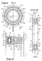
- the brake 100 comprises an annular body 110 with a cross-section substantially in the form of a "C" with parallel arms 111 defined for the sake of convenience as being longitudinal and a transverse arm 112 integral with a support flange 120 provided with holes 121 for fixing to fixed parts 3, as will emerge more clearly below in connection with Fig. 3.
- the annular body 110 forms essentially a C-shaped seat 110a which houses a coil 130 kept in position in a conventional manner, for example by means of resins or the like, and provided with an associated power supply cable 131 which emerges from the flange via a corresponding hole 113 and is connected to the control and actuating means (not shown).
- a closing ring 140 which is made of foil material with a low carbon content, shaped so as to have undercuts 140a extending over angular circumferential sections and able to produce segments of radial discontinuity of contact between the longitudinal arms 111 of the "C” and therefore a deviation of the linked magnetic flux produced by the electromagnet, as will emerge more clearly below in connection with operation of the brake/clutch assembly shown in Fig. 3.
- the ring In addition to the undercuts 140a the ring also has radial reliefs 140b which are arranged in suitable angular positions and are able to engage with the corresponding longitudinal arms 111 of the "C" in order to produce stable anchoring of the ring 140 to the said "C” so that the former is locked both rotationally and as regards axial displacement relative to the latter.
- reliefs 140b may, however, form an element for dispersion of the linked magnetic flux; a second embodiment of the brake is therefore also envisaged (shown in Figs. 4-6), wherein the closing ring is made as two parts, respectively formed by a base 1140, made of non-magnetic material, with the undercuts 1140a and the extensions 1140b, and a ring 1141, made of friction material, fixed to the base 1140 by means of screws/spot welds 1142.
- the non-magnetic material obliges the whole magnetic flux to follow the path shown in Fig. 6, limiting the amount of dispersion and increasingly, consequently, the torque available.
- the brake according to the invention has a friction surface 140c formed by the closing ring 140 and also by the front end surfaces of the longitudinal arms 111 of the "C", while the transverse arm 112 does not have a working function and is merely used for fastening, for example by means of welding, to the support flange 120.
- annular C-shaped body 110 may be made of material with a low carbon content in the form of a foil or sheet which can be cold-deformed.
- the closing ring consists of a base 1140 made of non-magnetic material fixed to the ring 1141 by means of spot welds and/or screws.
- the brake 100 according to the invention is suitable for forming part of an assembly consisting of brake 100 / clutch 200 for actuating / stopping the shaft 1 of a weaving/textile machine on which it is mounted, the assembly being integral with the fixed parts 3 of the machine.
- the shaft 1 also has, mounted thereon in a manner which is conventional and therefore neither illustrated nor described in detail, an armature 2 able to be displaced in an axial direction upon recall of the electromagnetic clutch 200, which is in turn conventional, for coupling to a rotor 210 for transmission of the movement, or to the brake 100, according to the present invention, for stopping the movement of the shaft 1.
- the electromagnetic circuit of the brake 100 is of the so-called "double" type namely with a path of the linked magnetic flux having a dual input/output from the armature 2 in order to increase the useful torque without modifying the dimensions, the double circuit being defined by the above-described annular undercuts 140a of the closing ring 140 which, causing an interruption in the ferromagnetic material, oblige the magnetic flux to follow the path shown in the figure.
Landscapes
- Engineering & Computer Science (AREA)
- General Engineering & Computer Science (AREA)
- Physics & Mathematics (AREA)
- Electromagnetism (AREA)
- Mechanical Engineering (AREA)
- Braking Arrangements (AREA)
Applications Claiming Priority (2)
| Application Number | Priority Date | Filing Date | Title |
|---|---|---|---|
| ITMI20040353 ITMI20040353A1 (it) | 2004-02-27 | 2004-02-27 | Freno particolarmenten per macchine di armatura |
| ITMI20040353 | 2004-02-27 |
Publications (1)
| Publication Number | Publication Date |
|---|---|
| EP1568909A1 true EP1568909A1 (de) | 2005-08-31 |
Family
ID=34746710
Family Applications (1)
| Application Number | Title | Priority Date | Filing Date |
|---|---|---|---|
| EP05075383A Withdrawn EP1568909A1 (de) | 2004-02-27 | 2005-02-17 | Bremse, insbesondere für eine Webmaschne |
Country Status (3)
| Country | Link |
|---|---|
| EP (1) | EP1568909A1 (de) |
| CN (1) | CN1661146A (de) |
| IT (1) | ITMI20040353A1 (de) |
Families Citing this family (1)
| Publication number | Priority date | Publication date | Assignee | Title |
|---|---|---|---|---|
| DE102006017182B3 (de) * | 2006-04-12 | 2007-09-06 | Lindauer Dornier Gmbh | Verfahren und Antriebsanordnung zum Betreiben einer Webmaschine |
Citations (5)
| Publication number | Priority date | Publication date | Assignee | Title |
|---|---|---|---|---|
| US2351598A (en) * | 1941-12-03 | 1944-06-20 | Warner Electric Brake Mfg Co | Electromagnetic friction device |
| US2549217A (en) * | 1949-09-27 | 1951-04-17 | Warner Electric Brake & Clutch | Friction brake cooling system |
| US2832918A (en) * | 1955-04-07 | 1958-04-29 | Warner Electric Brake & Clutch | Magnetic device and control therefor |
| US4235311A (en) * | 1977-10-22 | 1980-11-25 | K. Ernst Brinkmann, Industrieverwaltung | Mechanism for adjusting the air gap between the components of an electromagnetic brake |
| US4387794A (en) * | 1979-12-04 | 1983-06-14 | Zahnradfabrik Friedrichshafen Aktiengesellschaft | Single-surface electromagnetically operated clutch/brake unit |
-
2004
- 2004-02-27 IT ITMI20040353 patent/ITMI20040353A1/it unknown
-
2005
- 2005-02-17 EP EP05075383A patent/EP1568909A1/de not_active Withdrawn
- 2005-02-25 CN CN 200510052420 patent/CN1661146A/zh active Pending
Patent Citations (5)
| Publication number | Priority date | Publication date | Assignee | Title |
|---|---|---|---|---|
| US2351598A (en) * | 1941-12-03 | 1944-06-20 | Warner Electric Brake Mfg Co | Electromagnetic friction device |
| US2549217A (en) * | 1949-09-27 | 1951-04-17 | Warner Electric Brake & Clutch | Friction brake cooling system |
| US2832918A (en) * | 1955-04-07 | 1958-04-29 | Warner Electric Brake & Clutch | Magnetic device and control therefor |
| US4235311A (en) * | 1977-10-22 | 1980-11-25 | K. Ernst Brinkmann, Industrieverwaltung | Mechanism for adjusting the air gap between the components of an electromagnetic brake |
| US4387794A (en) * | 1979-12-04 | 1983-06-14 | Zahnradfabrik Friedrichshafen Aktiengesellschaft | Single-surface electromagnetically operated clutch/brake unit |
Also Published As
| Publication number | Publication date |
|---|---|
| CN1661146A (zh) | 2005-08-31 |
| ITMI20040353A1 (it) | 2004-05-27 |
Similar Documents
| Publication | Publication Date | Title |
|---|---|---|
| US20090133981A1 (en) | Gear Shifting Point for the Establishment of a Connection, Fixed Against Rotation, Between a Gear and a Shaft | |
| JP5608965B2 (ja) | ブレーキ付電磁クラッチ | |
| JPH09229105A (ja) | 自己保持型連結装置 | |
| US11371569B2 (en) | Selectable one-way clutch with common coil unit and axially moveable armature for active strut actuation | |
| JP2019105370A (ja) | 車両差動装置のための電磁アクチュエータ | |
| US11022186B2 (en) | Selectable one-way coupling with debris containment | |
| CA2831777C (en) | Electromagnetic clutch | |
| US3842378A (en) | Double clutch for vehicle air conditioning compressor | |
| JP2011169381A (ja) | 電磁連結装置 | |
| US3724619A (en) | Self-adjusting electromagnetic clutch-brake | |
| KR20160003856A (ko) | 전자 액추에이터 | |
| EP1568909A1 (de) | Bremse, insbesondere für eine Webmaschne | |
| KR102583668B1 (ko) | 소형 브레이크 및 그 조립 방법 | |
| US7581628B2 (en) | Electromagnetic clutch | |
| US4589536A (en) | Electromagnetic friction clutch | |
| JP4461375B2 (ja) | モータの軸受構造 | |
| CN100406764C (zh) | 压缩机的电磁离合器 | |
| JP5910472B2 (ja) | クラッチ機構 | |
| EP0287717B1 (de) | Federkupplung | |
| JPS595234Y2 (ja) | 電磁クラツチ・ブレ−キの自動空隙調整装置 | |
| JP5955237B2 (ja) | ブレーキ付き回転電機 | |
| EP0313680B1 (de) | Elektromagnetische Kupplungsvorrichtung | |
| JP2008309265A (ja) | 電磁連結装置 | |
| JPS6314105Y2 (de) | ||
| JPS6113780Y2 (de) |
Legal Events
| Date | Code | Title | Description |
|---|---|---|---|
| PUAI | Public reference made under article 153(3) epc to a published international application that has entered the european phase |
Free format text: ORIGINAL CODE: 0009012 |
|
| AK | Designated contracting states |
Kind code of ref document: A1 Designated state(s): AT BE BG CH CY CZ DE DK EE ES FI FR GB GR HU IE IS IT LI LT LU MC NL PL PT RO SE SI SK TR |
|
| AX | Request for extension of the european patent |
Extension state: AL BA HR LV MK YU |
|
| AKX | Designation fees paid | ||
| REG | Reference to a national code |
Ref country code: DE Ref legal event code: 8566 |
|
| STAA | Information on the status of an ep patent application or granted ep patent |
Free format text: STATUS: THE APPLICATION IS DEEMED TO BE WITHDRAWN |
|
| 18D | Application deemed to be withdrawn |
Effective date: 20060301 |