EP1569827B1 - Charniere destinee a relier un capot, notamment un capot moteur, a la carrosserie d'un vehicule - Google Patents
Charniere destinee a relier un capot, notamment un capot moteur, a la carrosserie d'un vehicule Download PDFInfo
- Publication number
- EP1569827B1 EP1569827B1 EP03778242A EP03778242A EP1569827B1 EP 1569827 B1 EP1569827 B1 EP 1569827B1 EP 03778242 A EP03778242 A EP 03778242A EP 03778242 A EP03778242 A EP 03778242A EP 1569827 B1 EP1569827 B1 EP 1569827B1
- Authority
- EP
- European Patent Office
- Prior art keywords
- hinge
- connecting part
- airbag
- carrier
- hood
- Prior art date
- Legal status (The legal status is an assumption and is not a legal conclusion. Google has not performed a legal analysis and makes no representation as to the accuracy of the status listed.)
- Expired - Lifetime
Links
- 230000005540 biological transmission Effects 0.000 claims description 10
- 238000000926 separation method Methods 0.000 description 4
- 206010039203 Road traffic accident Diseases 0.000 description 1
- 238000013459 approach Methods 0.000 description 1
- 238000007664 blowing Methods 0.000 description 1
- 238000013016 damping Methods 0.000 description 1
- 238000004090 dissolution Methods 0.000 description 1
- 239000002360 explosive Substances 0.000 description 1
- 238000009434 installation Methods 0.000 description 1
- 238000004904 shortening Methods 0.000 description 1
Images


Classifications
-
- B—PERFORMING OPERATIONS; TRANSPORTING
- B60—VEHICLES IN GENERAL
- B60R—VEHICLES, VEHICLE FITTINGS, OR VEHICLE PARTS, NOT OTHERWISE PROVIDED FOR
- B60R21/00—Arrangements or fittings on vehicles for protecting or preventing injuries to occupants or pedestrians in case of accidents or other traffic risks
- B60R21/34—Protecting non-occupants of a vehicle, e.g. pedestrians
- B60R21/38—Protecting non-occupants of a vehicle, e.g. pedestrians using means for lifting bonnets
-
- E—FIXED CONSTRUCTIONS
- E05—LOCKS; KEYS; WINDOW OR DOOR FITTINGS; SAFES
- E05D—HINGES OR SUSPENSION DEVICES FOR DOORS, WINDOWS OR WINGS
- E05D11/00—Additional features or accessories of hinges
-
- B—PERFORMING OPERATIONS; TRANSPORTING
- B60—VEHICLES IN GENERAL
- B60R—VEHICLES, VEHICLE FITTINGS, OR VEHICLE PARTS, NOT OTHERWISE PROVIDED FOR
- B60R21/00—Arrangements or fittings on vehicles for protecting or preventing injuries to occupants or pedestrians in case of accidents or other traffic risks
- B60R21/34—Protecting non-occupants of a vehicle, e.g. pedestrians
- B60R21/36—Protecting non-occupants of a vehicle, e.g. pedestrians using airbags
-
- E—FIXED CONSTRUCTIONS
- E05—LOCKS; KEYS; WINDOW OR DOOR FITTINGS; SAFES
- E05Y—INDEXING SCHEME ASSOCIATED WITH SUBCLASSES E05D AND E05F, RELATING TO CONSTRUCTION ELEMENTS, ELECTRIC CONTROL, POWER SUPPLY, POWER SIGNAL OR TRANSMISSION, USER INTERFACES, MOUNTING OR COUPLING, DETAILS, ACCESSORIES, AUXILIARY OPERATIONS NOT OTHERWISE PROVIDED FOR, APPLICATION THEREOF
- E05Y2900/00—Application of doors, windows, wings or fittings thereof
- E05Y2900/50—Application of doors, windows, wings or fittings thereof for vehicles
- E05Y2900/53—Type of wing
- E05Y2900/536—Hoods
Definitions
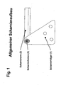
- the invention relates to a hinge for connecting a flap, in particular a bonnet to a vehicle body according to the preamble of claim 1.
- a hinge for connecting a hood to a motor vehicle in which a hinge arm is connected to a hinge support via a connecting part, which consists of a bolt and an elastic jacket surrounding the bolt.
- a connecting part which consists of a bolt and an elastic jacket surrounding the bolt.
- an airbag is used, which exerts a tensile force on the connecting part when filled with gas and this draws in the radial direction relative to the hinge pin from the hinge carrier.
- Object of the present invention is to provide a hinge that allows improved pedestrian protection.
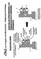
- a hinge for connecting a flap with at least one arranged on the vehicle body hinge carrier, at least one arranged on the flap hinge arm and at least one connecting part for pivotable about a hinge axis connection of the hinge arm on the hinge support, wherein the connection of the hinge arm to the Hinge carrier through the connecting part is released in an accident by removing the connecting part under the action of force along the hinge axis.
- the release of the engine hood hinge can be done by a complete separation of the hood and the vehicle body, in which case an additional device is provided, which limits the movement of the hood.
- the release of the bonnet hinge can be accomplished by releasing only parts of the hinge connection so that there is no complete separation between the bonnet and the vehicle body, with the desired freedom of movement being provided while the bonnet is raised. Due to the non-separate connection can also be limited in this case, the movement of the hood.
- claims 2 to 19 are different ways to release the flap, in particular the hood against the vehicle body executed. These principles include the use of an airbag to release the hinge. When using removable connecting parts using an airbag to raise the hood, it makes sense to initiate the airbag forces as close to the shame as possible.
- the expansion of the airbag can be used to exert tensile or shear forces on a connecting element connecting the two hinge parts, in particular a bolt, this bolt then being brought out of engagement with at least one of the two other hinge parts by the applied forces.
- tethers can be used, wherein the elongation behavior of the tethers and additional introduced in the tether tears can help that the hood moves as gently as possible at a defined level of force in their established end position. In this way, vibrations of the hood can be reduced in connection with the installation and the period for the damping of unavoidable vibrations can be reduced.
- the complete or partial dissolution of the hinge connection makes it possible to move the hood around a pivot point on the front of the vehicle. Unintended damage to the bonnet, the hinge and the adjacent vehicle areas can be minimized.
- the pivot point can be laid, for example, by a lever mechanism so that the bonnet is freely pivotable in the desired range, without abutting other vehicle areas.
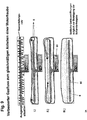
- FIG. 4 a first embodiment of the hinge according to the invention is shown.
- the connecting part in the form of a bolt 3 is connected via a transmission element 5 with an airbag bypass 4.
- the elastic airbag bypass 4 expands and pulls the bolt 3 out of its original position via the transmission element 5.
- Hinge carrier 1 and connecting arm 2 are released from each other.
- FIG. 5 a second embodiment of the hinge according to the invention is shown, in which the airbag 6 in its original state has a greater length, as in its inflated state.
- the airbag 6 is connected via a transmission element 5 with the bolt 3 of the hinge. If the airbag 6 inflated, so shortens its original length and the bolt 3 is pulled over the transmission element 5 from its connection, whereby hinge arm 2 and hinge carrier 1 are released from each other.
- the bolt 3 can be biased here with a spring, just as in the in FIG. 4 shown embodiment. As the airbag slackens, the bolt will snap back to its original position.
- a hinge is shown in the form of a spherical hinge.
- the connecting part 3 is formed here in the form of a ball which attaches directly to the hinge arm 2.
- the spherical connection part 3 is accommodated in a two-part hinge support, which consists of a fixed part 10 and a part 11 pivotable about an axis 12.
- the spherical connecting part 3 is received in corresponding receptacles of the hinge carrier parts 10 and 11.
- the hinge carrier parts 10, 11 are connected to each other via a bracket 13.
- FIG. 7 an embodiment is shown in which the hinge arm 2 has a deformation region 20 in which the hinge arm 2 can deform. If an airbag arranged under the hood is ignited, the deformation area 20 of the hinge arm 2 is deformed, so that the connecting part 3 is deformed from a Receiving 100 of the hinge carrier 1 migrates out and so releases the connection. The wandering occurs due to the projected to the receptacle 100 shortening of the hinge arm 2.
- the opening movement is controlled by a lever 4, which moves in a gate 40 on the hinge support 1. As a result, a defined opening behavior can be achieved.
- In the upper area of the FIG. 7 is another possible slotted guide, shown for example for the connecting part 3.
- the connecting part 3 In an initial position, the connecting part 3 is clamped in the region 41 of the slide guide behind a locking element 42. If an airbag is deployed, the part 3 moves in the direction indicated by the arrow path past a one-way flap 43 in the open position 45. After the accident, the flap front section 45 can be brought by pushing down again past the one-way flap 43 in a transport position 44 in which a trip to the next workshop is possible.
- FIG. 8 a further embodiment of the invention is shown in which the deployment of an airbag 6 via a trained as a lever 6 transmission element in turn acts on the bolt 3 such that at a deployment of the airbag 6 of the bolt is pulled out of its connection.
- the airbag operates here in the form of a piston and adjoins piston-shaped caps 62.
- FIG. 9 a particular embodiment of a suitable airbag 6 is shown.
- the gas bag is positioned in the vehicle so that it is in close proximity to the hinges of the hood.
- a gas lance 60 is arranged, the outlet openings are also arranged in close proximity to the hinges. If a gas for the deployment of the gas bag 6 is generated by the gas generator 61, the gas bag area, which is located in the area of the hinges, is first inflated as shown in I. Only then does the remaining gas bag unfold. This ensures that initially occur in the hinges Vors tenufte that allow a solution of the hinge and only then the rest of the hood is raised. This prevents the hood from causing unnecessary vibrations.
Landscapes
- Engineering & Computer Science (AREA)
- Mechanical Engineering (AREA)
- Superstructure Of Vehicle (AREA)
Claims (19)
- Charnière destinée à relier un capot, notamment un capot moteur, à la carrosserie d'un véhicule avec au moins un support (1) de charnière disposé sur la carrosserie du véhicule, au moins un bras de charnière (2) disposé sur le capot et au moins une partie de liaison (3) pour relier le bras de charnière (2) au support (1) de charnière, de manière pivotante autour d'un axe de charnière,
caractérisée en ce
qu'en cas d'accident, la liaison entre le bras de charnière (2) et le support (1) de charnière est détachée par retrait de la partie de liaison (3) sous l'effet de forces le long de l'axe de charnière, un airbag étant utilisé pour libérer la charnière. - Charnière selon la revendication 1, caractérisée en ce que la partie de liaison (3) est réalisée comme un boulon de cisaillement.
- Charnière selon la revendication 1 ou 2, caractérisée en ce que la partie de liaison (3) est guidée dans au moins un logement du bras de charnière (2) et au moins un logement du support (1) de charnière et en cas d'accident est retirée d'au moins un logement.
- Charnière selon la revendication 3, caractérisée en ce que la partie de liaison (3) est réalisée comme un boulon qui est extrait d'au moins l'un des logements.
- Charnière selon la revendication 3 ou 4, caractérisée en ce qu'au moins un moyen d'actionnement est prévu pour l'actionnement de la partie de liaison (3) en cas d'accident.
- Charnière selon la revendication 5, caractérisée en ce que le moyen d'actionnement comporte un élément pyrotechnique.
- Charnière selon la revendication 5 ou 6, caractérisée en ce que le moyen d'actionnement est un sac de gaz (6) pouvant être gonflé et/ou un élément conduisant du gaz.
- Charnière selon la revendication 7, caractérisée en ce que le sac de gaz (6) et/ou l'élément conduisant du gaz (4) agit par le biais d'au moins un élément de transmission (5) sur la partie de liaison (3).
- Charnière selon la revendication 8, caractérisée en ce que l'élément de transmission (5) est réalisé comme un levier.
- Charnière selon l'une quelconque des revendications 7 à 9, caractérisée en ce que le sac de gaz (6) et/ou l'élément conduisant du gaz (4) exerce lors du remplissage en gaz une pression ou une traction sur la partie de liaison (3) et/ou l'élément de transmission (5) en raison de son expansion.
- Charnière selon l'une quelconque des revendications précédentes, caractérisée en ce que la partie de liaison (3) est réalisée comme une sphère et le support (1) de charnière présente au moins un logement correspondant à la partie de liaison (3) qui est réalisé de telle sorte qu'il libère la partie de liaison (3) en cas d'accident.
- Charnière selon la revendication 11, caractérisée en ce que le support (1) de charnière présente au moins un élément de support de charnière (11) mobile qui est déplacé en cas d'accident par rapport à au moins un élément de support de charnière (10) fixe de telle sorte que la partie de liaison (3) logée dedans se libère.
- Charnière selon l'une quelconque des revendications précédentes, caractérisée en ce que le bras de charnière (2) présente une zone de déformation (20) pour la déformation ciblée du bras de charnière (2) en cas d'accident.
- Charnière selon la revendication 13, caractérisée en ce que la partie de liaison (3) se désengage avec le support (1) de charnière par la déformation du bras de charnière (2).
- Charnière selon l'une quelconque des revendications précédentes, caractérisée en ce qu'au moins un moyen de limitation pour limiter le mouvement relatif est disposé entre le support (1) de charnière et le bras de charnière (2).
- Charnière selon la revendication 1 S, caractérisée en ce que le moyen de limitation est une bande d'arrêt et/ou un levier (4) guidé dans une coulisse (40).
- Charnière selon la revendication 7 ou l'une quelconque des revendications 8 à 16, dans la mesure où relative à la revendication 7, caractérisée en ce que des zones de sac de gaz sont disposées directement sur la charnière.
- Charnière selon la revendication 17, caractérisée en ce que le sac de gaz (6) se déploie lors de son déploiement tout d'abord dans les zones disposées sur la charnière.
- Charnière selon la revendication 17 ou 18, caractérisée en ce qu'un système de conduite de gaz (60), en particulier une lance à gaz, est disposée à l'intérieur du sac de gaz (6), laquelle conduit le gaz servant au déploiement dans les zones de sac de gaz disposées sur la charnière.
Applications Claiming Priority (3)
| Application Number | Priority Date | Filing Date | Title |
|---|---|---|---|
| DE10252285A DE10252285A1 (de) | 2002-11-06 | 2002-11-06 | Scharnier zur Anbindung einer Klappe, insbesondere einer Motorhaube, an einem Fahrzeugkörper |
| DE10252285 | 2002-11-06 | ||
| PCT/DE2003/003597 WO2004041601A2 (fr) | 2002-11-06 | 2003-10-27 | Charniere destinee a relier un capot, notamment un capot moteur, a la carrosserie d'un vehicule |
Publications (2)
| Publication Number | Publication Date |
|---|---|
| EP1569827A2 EP1569827A2 (fr) | 2005-09-07 |
| EP1569827B1 true EP1569827B1 (fr) | 2010-06-23 |
Family
ID=32185443
Family Applications (1)
| Application Number | Title | Priority Date | Filing Date |
|---|---|---|---|
| EP03778242A Expired - Lifetime EP1569827B1 (fr) | 2002-11-06 | 2003-10-27 | Charniere destinee a relier un capot, notamment un capot moteur, a la carrosserie d'un vehicule |
Country Status (6)
| Country | Link |
|---|---|
| US (1) | US7537073B2 (fr) |
| EP (1) | EP1569827B1 (fr) |
| JP (1) | JP4249133B2 (fr) |
| CN (1) | CN100448721C (fr) |
| DE (2) | DE10252285A1 (fr) |
| WO (1) | WO2004041601A2 (fr) |
Families Citing this family (19)
| Publication number | Priority date | Publication date | Assignee | Title |
|---|---|---|---|---|
| FR2865451B1 (fr) * | 2004-01-23 | 2006-05-05 | Oxford Automotive Mecanismes E | Systeme de retenue du capot d'un vehicule automobile |
| DE102005016324B4 (de) * | 2005-04-09 | 2011-08-18 | GM Global Technology Operations LLC, ( n. d. Ges. d. Staates Delaware ), Mich. | Karosserie für ein Kraftfahrzeug |
| DE202005006655U1 (de) * | 2005-04-12 | 2005-08-25 | Drehtainer Gmbh Spezial Container- Und Fahrzeugbau | Geschütztes Fahrzeug oder Schiff |
| DE102005034558B4 (de) * | 2005-07-23 | 2008-12-04 | Bayerische Motoren Werke Aktiengesellschaft | Vorrichtung zum Aufstellen der Fronthaube eines Kraftfahrzeuges im Haubenscharnierbereich bei einem drohenden Personenaufprall |
| DE102005040706B4 (de) * | 2005-08-27 | 2007-09-20 | Automotive Group Ise Innomotive Systems Europe Gmbh | Pyrotechnisch auslösbare Haltevorrichtung für Schutzvorrichtungen in Kraftfahrzeugen |
| EP1842745B1 (fr) * | 2006-04-04 | 2011-08-17 | Ford Global Technologies, LLC | Butée de capot pour véhicule |
| US7597166B2 (en) * | 2006-04-20 | 2009-10-06 | Autoliv Asp, Inc. | Hinge device for pedestrian protection system |
| DE102006028595B4 (de) * | 2006-06-22 | 2015-02-05 | Dr. Ing. H.C. F. Porsche Aktiengesellschaft | Kraftfahrzeug |
| DE102007053172B4 (de) * | 2007-11-08 | 2023-07-27 | Dr. Ing. H.C. F. Porsche Aktiengesellschaft | Scharnier |
| US7730990B2 (en) * | 2008-05-13 | 2010-06-08 | Honda Motor Co., Ltd. | Restraint system for a hood lift device |
| DE102010009064B4 (de) * | 2010-02-23 | 2012-06-28 | Edscha Engineering Gmbh | Verriegelungsanordnung |
| DE102010029410A1 (de) * | 2010-05-27 | 2011-12-01 | Bayerische Motoren Werke Aktiengesellschaft | Feder- und Dämpfer-Baueinheit |
| US8768574B1 (en) | 2013-02-22 | 2014-07-01 | Ventra Group, Inc. | Pedestrian protection vehicle hood hinge assembly |
| EP2792554B1 (fr) * | 2013-04-19 | 2016-03-23 | Volvo Car Corporation | Agencement de capot |
| EP2907704B1 (fr) * | 2014-02-18 | 2017-01-04 | Volvo Car Corporation | Agencement comprenant un dispositif pyrotechnique et une première structure mécanique |
| DE202014008603U1 (de) | 2014-10-29 | 2016-02-01 | GM Global Technology Operations LLC (n. d. Ges. d. Staates Delaware) | Airbagmodulanordnung für ein Fahrzeug und Fahrzeug mit der Airbagmodulanordnung |
| KR101637747B1 (ko) | 2014-11-26 | 2016-07-07 | 현대자동차주식회사 | 파단형 후드 힌지장치 |
| DE102016004111A1 (de) | 2016-04-05 | 2017-10-05 | GM Global Technology Operations LLC (n. d. Ges. d. Staates Delaware) | Kraftfahrzeug mit Fußgänger-Airbag |
| JP7064457B2 (ja) * | 2019-02-19 | 2022-05-10 | 本田技研工業株式会社 | 車両のポップアップフード装置 |
Family Cites Families (32)
| Publication number | Priority date | Publication date | Assignee | Title |
|---|---|---|---|---|
| JPS58211975A (ja) | 1982-06-03 | 1983-12-09 | Nissan Motor Co Ltd | 自動車用フ−ドの支持構造 |
| JPH07267145A (ja) | 1994-03-30 | 1995-10-17 | Mazda Motor Corp | 自動車の後部車体構造 |
| JP4163272B2 (ja) | 1997-09-30 | 2008-10-08 | 日産自動車株式会社 | はね上げ式フード |
| JPH11310157A (ja) | 1998-04-27 | 1999-11-09 | Honda Motor Co Ltd | 車両用フードの衝撃吸収装置 |
| JP3687418B2 (ja) | 1998-06-26 | 2005-08-24 | 日産自動車株式会社 | 跳ね上げフード |
| DE50001209D1 (de) * | 1999-05-17 | 2003-03-13 | Edscha Ag | Fronthaubenanordnung |
| AU6147000A (en) * | 1999-05-17 | 2000-12-05 | Edscha Ag | Front hood assembly |
| JP3377763B2 (ja) * | 1999-07-08 | 2003-02-17 | 本田技研工業株式会社 | 車両用フード装置 |
| KR100339230B1 (ko) * | 1999-09-13 | 2002-05-31 | 이계안 | 자동차용 후드 힌지 |
| US6554093B2 (en) * | 2000-07-19 | 2003-04-29 | Honda Giken Kogyo Kabushiki Kaisha | Vehicular hood device |
| US6513617B2 (en) * | 2000-07-26 | 2003-02-04 | Honda Giken Kogyo Kabushiki Kaisha | Vehicle hood apparatus |
| JP2002068019A (ja) | 2000-08-31 | 2002-03-08 | Daihatsu Motor Co Ltd | 自動車のフード装置 |
| KR100362405B1 (ko) * | 2000-10-18 | 2002-11-25 | 기아자동차주식회사 | 충격 완충용 자동차의 본네트 후드 푸쉬 기구 |
| DE20017919U1 (de) * | 2000-10-19 | 2001-03-01 | TRW Occupant Restraint Systems GmbH & Co. KG, 73553 Alfdorf | Baugruppe bestehend aus Sitzlehne und Gassack-Modul |
| GB2368562B (en) * | 2000-11-03 | 2004-02-04 | Autoliv Dev | Improvements in or relating to an airbag arrangement |
| GB2372536B (en) | 2001-02-15 | 2003-09-10 | Ford Global Tech Inc | A hinge assembly and a motor vehicle including same |
| US6883557B1 (en) * | 2001-03-30 | 2005-04-26 | Berger Seiba-Technotex Verwaltungs Gmbh Co. | Method for weaving an airbag |
| KR100405541B1 (ko) * | 2001-05-18 | 2003-11-14 | 현대자동차주식회사 | 자동차의 후드 힌지구조 |
| DE10131120A1 (de) * | 2001-06-28 | 2003-02-06 | Trw Repa Gmbh | Baugruppe bestehend aus Fahrzeugkarosserie, Frontscheibe, Instrumententafel und Gassackmodul |
| DE10136897A1 (de) * | 2001-07-28 | 2003-02-06 | Opel Adam Ag | Doppelarmgelenkscharnier für die Fronthaube eines Kraftfahrzeuges |
| JP2003095044A (ja) * | 2001-09-06 | 2003-04-03 | Takata Corp | 外面展開型エアバッグ装置 |
| EP1438218B1 (fr) * | 2001-10-17 | 2005-06-15 | Volkswagen Aktiengesellschaft | Systeme d'airbag situe dans un vehicule, notamment une automobile |
| US7163232B2 (en) * | 2001-11-26 | 2007-01-16 | Nihon Plast Co., Ltd. | Curtain airbag and its folding method and system |
| JP3794325B2 (ja) * | 2001-12-27 | 2006-07-05 | トヨタ自動車株式会社 | 自動車のフード構造 |
| DE60311787T2 (de) * | 2002-04-17 | 2007-06-14 | Autoliv Development Ab | Sicherheitsvorrichtung zum anheben des hinteren teils der motorhaube eines kraftfahrzeugs |
| DE10249375A1 (de) * | 2002-10-23 | 2004-05-19 | Trw Occupant Restraint Systems Gmbh & Co. Kg | Gassackmodul mit Gaslanze |
| US7712569B2 (en) * | 2003-06-06 | 2010-05-11 | Magna Electronics Europe Gmbh & Co. Kg | Device and method for raising the hood of a motor vehicle during a collision with a pedestrian |
| CH703690B1 (it) * | 2004-05-10 | 2012-03-15 | Protoscar Sa | Elemento costruttivo gonfiabile pneumaticamente per autoveicoli. |
| US7303040B2 (en) * | 2004-05-18 | 2007-12-04 | Autolive Asp, Inc. | Active vehicle hood system and method |
| DE102004032315B4 (de) * | 2004-07-03 | 2006-08-03 | Adam Opel Ag | Kraftfahrzeug mit anhebbarer Haube |
| JP2006240558A (ja) * | 2005-03-07 | 2006-09-14 | Mazda Motor Corp | 車両用歩行者保護装置 |
| JP4569421B2 (ja) * | 2005-08-29 | 2010-10-27 | マツダ株式会社 | 車両用歩行者保護装置 |
-
2002
- 2002-11-06 DE DE10252285A patent/DE10252285A1/de not_active Withdrawn
-
2003
- 2003-10-27 DE DE50312834T patent/DE50312834D1/de not_active Expired - Lifetime
- 2003-10-27 EP EP03778242A patent/EP1569827B1/fr not_active Expired - Lifetime
- 2003-10-27 CN CNB2003801029026A patent/CN100448721C/zh not_active Expired - Fee Related
- 2003-10-27 JP JP2004549070A patent/JP4249133B2/ja not_active Expired - Fee Related
- 2003-10-27 US US10/534,064 patent/US7537073B2/en not_active Expired - Fee Related
- 2003-10-27 WO PCT/DE2003/003597 patent/WO2004041601A2/fr not_active Ceased
Also Published As
| Publication number | Publication date |
|---|---|
| CN100448721C (zh) | 2009-01-07 |
| WO2004041601A2 (fr) | 2004-05-21 |
| DE10252285A1 (de) | 2004-05-27 |
| US20060151221A1 (en) | 2006-07-13 |
| WO2004041601A3 (fr) | 2004-07-15 |
| EP1569827A2 (fr) | 2005-09-07 |
| CN1711187A (zh) | 2005-12-21 |
| JP2006505440A (ja) | 2006-02-16 |
| JP4249133B2 (ja) | 2009-04-02 |
| DE50312834D1 (de) | 2010-08-05 |
| US7537073B2 (en) | 2009-05-26 |
Similar Documents
| Publication | Publication Date | Title |
|---|---|---|
| EP1569827B1 (fr) | Charniere destinee a relier un capot, notamment un capot moteur, a la carrosserie d'un vehicule | |
| DE602004007901T2 (de) | Vorrichtung zur Verringerung des Aufpralls von Fussgängern | |
| DE60301778T2 (de) | Sicherheitseinrichtung zum Anheben einer Motorhaube bei einem Zusammenstoss | |
| DE102015113628B4 (de) | Ausfahrbarer Fahrzeughaubenverlängerer für den Fussgängerschutz | |
| DE10316026B4 (de) | Entgasungssystem für Airbag | |
| EP0885783B1 (fr) | Dispositif de protection des genoux dans un véhicule | |
| EP2718155B1 (fr) | Système de retenue de siège de véhicule avec sac gonflable de genoux | |
| DE102004062105B4 (de) | Vorrichtung zum Schutz von Personen bei einem Frontalaufprall auf ein Kraftfahrzeug durch aktives Aufstellen dessen Fronthaube | |
| DE10033148A1 (de) | Haubenkonstruktion für ein Fahrzeug | |
| EP2257449B1 (fr) | Pièce d'équipement avec volet de sortie de coussin gonflable | |
| DE10152621A1 (de) | Anordnung einer Frontklappe an einem Fahrzeug | |
| DE19957872B4 (de) | Sicherheitseinrichtung an einem Fahrzeug zum Schutz von Fußgängern | |
| DE19957868A1 (de) | Sicherheitseinrichtung an einem Fahrzeug zum Schutz von Fußgängern | |
| DE102021102813A1 (de) | Fahrzeugsitz mit einem sitzunterseiten-vorderrand-airbag | |
| DE19750182A1 (de) | Airbagmodul mit einem Antrieb für die Abdeckklappe | |
| DE10020929A1 (de) | Airbagmodul | |
| DE19733896A1 (de) | Airbagvorrichtung | |
| EP1134131B1 (fr) | Dispositif de direction pour véhicule automobile équipé d'un module à sac gonflable | |
| DE112006003329B4 (de) | Gassack-Anordnung | |
| DE102017216180A1 (de) | Sicherheitsgurtanordnungen für ein Kraftfahrzeug | |
| EP1745993B1 (fr) | Dispositif de levage pour capot moteur d'un véhicule automobile | |
| DE10239352A1 (de) | Sicherheitseinrichtung für ein Fahrzeug zum Schutz von Fußgängern oder dergleichen | |
| DE102021205306A1 (de) | Fussgängerschutz kfz-scharnier | |
| EP1360094B1 (fr) | Dispositif et procede de recouvrement d'airbag | |
| DE19846853A1 (de) | Verfahren zum Entfalten eines Luftsacks |
Legal Events
| Date | Code | Title | Description |
|---|---|---|---|
| PUAI | Public reference made under article 153(3) epc to a published international application that has entered the european phase |
Free format text: ORIGINAL CODE: 0009012 |
|
| 17P | Request for examination filed |
Effective date: 20050531 |
|
| AK | Designated contracting states |
Kind code of ref document: A2 Designated state(s): AT BE BG CH CY CZ DE DK EE ES FI FR GB GR HU IE IT LI LU MC NL PT RO SE SI SK TR |
|
| RBV | Designated contracting states (corrected) |
Designated state(s): DE FR GB SE |
|
| RIN1 | Information on inventor provided before grant (corrected) |
Inventor name: KALLISKE, INGO Inventor name: MARKFORT, DIETER Inventor name: FELKE, MARKUS |
|
| 17Q | First examination report despatched |
Effective date: 20080619 |
|
| GRAP | Despatch of communication of intention to grant a patent |
Free format text: ORIGINAL CODE: EPIDOSNIGR1 |
|
| GRAS | Grant fee paid |
Free format text: ORIGINAL CODE: EPIDOSNIGR3 |
|
| GRAA | (expected) grant |
Free format text: ORIGINAL CODE: 0009210 |
|
| AK | Designated contracting states |
Kind code of ref document: B1 Designated state(s): DE FR GB SE |
|
| REF | Corresponds to: |
Ref document number: 50312834 Country of ref document: DE Date of ref document: 20100805 Kind code of ref document: P |
|
| PG25 | Lapsed in a contracting state [announced via postgrant information from national office to epo] |
Ref country code: SE Free format text: LAPSE BECAUSE OF FAILURE TO SUBMIT A TRANSLATION OF THE DESCRIPTION OR TO PAY THE FEE WITHIN THE PRESCRIBED TIME-LIMIT Effective date: 20100623 |
|
| PLBE | No opposition filed within time limit |
Free format text: ORIGINAL CODE: 0009261 |
|
| STAA | Information on the status of an ep patent application or granted ep patent |
Free format text: STATUS: NO OPPOSITION FILED WITHIN TIME LIMIT |
|
| 26N | No opposition filed |
Effective date: 20110324 |
|
| GBPC | Gb: european patent ceased through non-payment of renewal fee |
Effective date: 20101027 |
|
| REG | Reference to a national code |
Ref country code: DE Ref legal event code: R097 Ref document number: 50312834 Country of ref document: DE Effective date: 20110323 |
|
| PG25 | Lapsed in a contracting state [announced via postgrant information from national office to epo] |
Ref country code: GB Free format text: LAPSE BECAUSE OF NON-PAYMENT OF DUE FEES Effective date: 20101027 |
|
| REG | Reference to a national code |
Ref country code: DE Ref legal event code: R082 Ref document number: 50312834 Country of ref document: DE Representative=s name: MAIKOWSKI & NINNEMANN PATENTANWAELTE, DE |
|
| REG | Reference to a national code |
Ref country code: DE Ref legal event code: R081 Ref document number: 50312834 Country of ref document: DE Owner name: TAKATA AKTIENGESELLSCHAFT, DE Free format text: FORMER OWNER: TAKATA-PETRI AG, 63743 ASCHAFFENBURG, DE Effective date: 20120904 Ref country code: DE Ref legal event code: R082 Ref document number: 50312834 Country of ref document: DE Representative=s name: MAIKOWSKI & NINNEMANN PATENTANWAELTE, DE Effective date: 20120904 Ref country code: DE Ref legal event code: R082 Ref document number: 50312834 Country of ref document: DE Representative=s name: MAIKOWSKI & NINNEMANN PATENTANWAELTE PARTNERSC, DE Effective date: 20120904 |
|
| REG | Reference to a national code |
Ref country code: FR Ref legal event code: PLFP Year of fee payment: 13 |
|
| PGFP | Annual fee paid to national office [announced via postgrant information from national office to epo] |
Ref country code: FR Payment date: 20150908 Year of fee payment: 13 |
|
| PGFP | Annual fee paid to national office [announced via postgrant information from national office to epo] |
Ref country code: DE Payment date: 20151020 Year of fee payment: 13 |
|
| REG | Reference to a national code |
Ref country code: DE Ref legal event code: R119 Ref document number: 50312834 Country of ref document: DE |
|
| REG | Reference to a national code |
Ref country code: FR Ref legal event code: ST Effective date: 20170630 |
|
| PG25 | Lapsed in a contracting state [announced via postgrant information from national office to epo] |
Ref country code: FR Free format text: LAPSE BECAUSE OF NON-PAYMENT OF DUE FEES Effective date: 20161102 Ref country code: DE Free format text: LAPSE BECAUSE OF NON-PAYMENT OF DUE FEES Effective date: 20170503 |