EP1570896A1 - Stoffaustauschapparat mit Hohlfasermembranen und Verfahren zu dessen Herstellung - Google Patents
Stoffaustauschapparat mit Hohlfasermembranen und Verfahren zu dessen Herstellung Download PDFInfo
- Publication number
- EP1570896A1 EP1570896A1 EP05003822A EP05003822A EP1570896A1 EP 1570896 A1 EP1570896 A1 EP 1570896A1 EP 05003822 A EP05003822 A EP 05003822A EP 05003822 A EP05003822 A EP 05003822A EP 1570896 A1 EP1570896 A1 EP 1570896A1
- Authority
- EP
- European Patent Office
- Prior art keywords
- hollow fiber
- fiber membrane
- membrane contactor
- contactor according
- shaped design
- Prior art date
- Legal status (The legal status is an assumption and is not a legal conclusion. Google has not performed a legal analysis and makes no representation as to the accuracy of the status listed.)
- Withdrawn
Links
- 239000012510 hollow fiber Substances 0.000 title claims abstract description 102
- 239000012528 membrane Substances 0.000 title claims abstract description 68
- 238000004519 manufacturing process Methods 0.000 title claims abstract description 25
- 238000004382 potting Methods 0.000 claims abstract description 63
- 239000000463 material Substances 0.000 claims abstract description 42
- 238000005304 joining Methods 0.000 claims abstract description 4
- 239000004744 fabric Substances 0.000 claims description 37
- 238000000034 method Methods 0.000 claims description 20
- 238000003466 welding Methods 0.000 claims description 11
- 229920001187 thermosetting polymer Polymers 0.000 claims description 9
- 239000012815 thermoplastic material Substances 0.000 claims description 8
- 229920000098 polyolefin Polymers 0.000 claims description 7
- 239000004593 Epoxy Substances 0.000 claims description 6
- 125000003700 epoxy group Chemical group 0.000 claims description 4
- 230000005484 gravity Effects 0.000 claims description 4
- 229920000647 polyepoxide Polymers 0.000 claims description 4
- 229920002635 polyurethane Polymers 0.000 claims description 4
- 239000004814 polyurethane Substances 0.000 claims description 4
- 238000004026 adhesive bonding Methods 0.000 claims description 3
- 239000000835 fiber Substances 0.000 claims description 3
- 125000006850 spacer group Chemical group 0.000 claims description 3
- 239000002904 solvent Substances 0.000 claims description 2
- 238000004804 winding Methods 0.000 claims description 2
- -1 polypropylene Polymers 0.000 description 14
- 239000012530 fluid Substances 0.000 description 10
- 239000004698 Polyethylene Substances 0.000 description 6
- 239000004743 Polypropylene Substances 0.000 description 6
- 239000012466 permeate Substances 0.000 description 6
- 229920000573 polyethylene Polymers 0.000 description 6
- 229920001155 polypropylene Polymers 0.000 description 6
- 239000007788 liquid Substances 0.000 description 5
- 229920001169 thermoplastic Polymers 0.000 description 5
- 239000004416 thermosoftening plastic Substances 0.000 description 4
- 239000004800 polyvinyl chloride Substances 0.000 description 3
- 229920000915 polyvinyl chloride Polymers 0.000 description 3
- 239000004925 Acrylic resin Substances 0.000 description 2
- 229920000178 Acrylic resin Polymers 0.000 description 2
- 229920001730 Moisture cure polyurethane Polymers 0.000 description 2
- 239000004793 Polystyrene Substances 0.000 description 2
- XECAHXYUAAWDEL-UHFFFAOYSA-N acrylonitrile butadiene styrene Chemical compound C=CC=C.C=CC#N.C=CC1=CC=CC=C1 XECAHXYUAAWDEL-UHFFFAOYSA-N 0.000 description 2
- 239000004676 acrylonitrile butadiene styrene Substances 0.000 description 2
- 229920000122 acrylonitrile butadiene styrene Polymers 0.000 description 2
- 239000011324 bead Substances 0.000 description 2
- 229920002678 cellulose Polymers 0.000 description 2
- 239000001913 cellulose Substances 0.000 description 2
- 238000004891 communication Methods 0.000 description 2
- 239000002131 composite material Substances 0.000 description 2
- 238000010276 construction Methods 0.000 description 2
- 238000009792 diffusion process Methods 0.000 description 2
- 229920002313 fluoropolymer Polymers 0.000 description 2
- 229920001778 nylon Polymers 0.000 description 2
- 229920003229 poly(methyl methacrylate) Polymers 0.000 description 2
- 229920000642 polymer Polymers 0.000 description 2
- 239000004926 polymethyl methacrylate Substances 0.000 description 2
- 229920002223 polystyrene Polymers 0.000 description 2
- 239000000126 substance Substances 0.000 description 2
- 229920001059 synthetic polymer Polymers 0.000 description 2
- 229920000219 Ethylene vinyl alcohol Polymers 0.000 description 1
- 239000002033 PVDF binder Substances 0.000 description 1
- 239000004952 Polyamide Substances 0.000 description 1
- 239000004695 Polyether sulfone Substances 0.000 description 1
- 239000004697 Polyetherimide Substances 0.000 description 1
- 229920002367 Polyisobutene Polymers 0.000 description 1
- 230000008602 contraction Effects 0.000 description 1
- 238000007872 degassing Methods 0.000 description 1
- 238000009826 distribution Methods 0.000 description 1
- 239000004715 ethylene vinyl alcohol Substances 0.000 description 1
- 238000010438 heat treatment Methods 0.000 description 1
- RZXDTJIXPSCHCI-UHFFFAOYSA-N hexa-1,5-diene-2,5-diol Chemical compound OC(=C)CCC(O)=C RZXDTJIXPSCHCI-UHFFFAOYSA-N 0.000 description 1
- 239000002184 metal Substances 0.000 description 1
- 239000000203 mixture Substances 0.000 description 1
- 238000005192 partition Methods 0.000 description 1
- 229920003023 plastic Polymers 0.000 description 1
- 239000004033 plastic Substances 0.000 description 1
- 229920002492 poly(sulfone) Polymers 0.000 description 1
- 229920002647 polyamide Polymers 0.000 description 1
- 229920001748 polybutylene Polymers 0.000 description 1
- 229920000728 polyester Polymers 0.000 description 1
- 229920006393 polyether sulfone Polymers 0.000 description 1
- 229920001601 polyetherimide Polymers 0.000 description 1
- 229920000306 polymethylpentene Polymers 0.000 description 1
- 229920002981 polyvinylidene fluoride Polymers 0.000 description 1
- 230000000717 retained effect Effects 0.000 description 1
Images



Classifications
-
- B—PERFORMING OPERATIONS; TRANSPORTING
- B01—PHYSICAL OR CHEMICAL PROCESSES OR APPARATUS IN GENERAL
- B01D—SEPARATION
- B01D63/00—Apparatus in general for separation processes using semi-permeable membranes
- B01D63/02—Hollow fibre modules
- B01D63/021—Manufacturing thereof
- B01D63/0231—Manufacturing thereof using supporting structures, e.g. filaments for weaving mats
-
- B—PERFORMING OPERATIONS; TRANSPORTING
- B01—PHYSICAL OR CHEMICAL PROCESSES OR APPARATUS IN GENERAL
- B01D—SEPARATION
- B01D63/00—Apparatus in general for separation processes using semi-permeable membranes
- B01D63/02—Hollow fibre modules
- B01D63/021—Manufacturing thereof
- B01D63/022—Encapsulating hollow fibres
- B01D63/0221—Encapsulating hollow fibres using a mould
-
- B—PERFORMING OPERATIONS; TRANSPORTING
- B01—PHYSICAL OR CHEMICAL PROCESSES OR APPARATUS IN GENERAL
- B01D—SEPARATION
- B01D63/00—Apparatus in general for separation processes using semi-permeable membranes
- B01D63/02—Hollow fibre modules
- B01D63/021—Manufacturing thereof
- B01D63/022—Encapsulating hollow fibres
- B01D63/0222—Encapsulating hollow fibres using centrifugal forces
-
- B—PERFORMING OPERATIONS; TRANSPORTING
- B01—PHYSICAL OR CHEMICAL PROCESSES OR APPARATUS IN GENERAL
- B01D—SEPARATION
- B01D63/00—Apparatus in general for separation processes using semi-permeable membranes
- B01D63/02—Hollow fibre modules
- B01D63/033—Specific distribution of fibres within one potting or tube-sheet
Definitions
- the instant invention relates to a hollow fiber membrane contactor, and method of making same.
- a contactor is a mass transfer device that removes or adds a material to a fluid. Contactors may be used to remove or add gas to a fluid stream. Hollow fiber membrane contactors are known. For example, see U.S. Pat. Nos. 3,288,877; 3,755,034; 4,220,535; 4,664,681; 4,940,617; 5,186,832; 5,264,171; 5,284,584; and 5,449,457. Hollow fiber membrane contactors are commercially available under the name of LIQUI-CEL® from Celgard Inc. of Charlotte, N.C. and under the name of SEPAREL® from Dianippon Ink and Chemicals of Tokyo, Japan. Such contactors have numerous uses, one being the degassing of liquids.
- the hollow fiber membranes are typically formed into a fabric (e.g., woven or knitted).
- the fabric could be wound around a mandrel (e.g., a perforated center tube) and fixed into place by potting the fabric edges, with either thermosetting or thermoplastic materials, to form a unitized structure.
- a mandrel e.g., a perforated center tube
- This unit can then be inserted within a shell and sealed, i.e., with or without O-rings, to make a membrane contactor.
- U.S. Pat. No. 6,207,053 See, for example, U.S. Pat. No. 6,207,053.
- potting shrinkage and/or expansion it is difficult to maintain the seal between the unit and the shell in membrane contactors with large diameters.
- the instant invention is a hollow fiber membrane contactor, and method of making same.
- the hollow fiber membrane contactor includes (1) a shell, said shell having an internal bonding surface, an interlocking geometry ring being provided on said internal bonding surface; (2) a unitized structure; (3) a potting material joining said unitized structure to said shell at said interlocking geometry ring thereby forming an interlocking seal therebetween; and (4) end caps, said end caps being adjoined to lateral ends of said shell.
- the method of making a hollow fiber membrane contactor includes (1) providing a shell, said shell having an internal bonding surface; (2) providing an interlocking geometry ring on said internal bonding surface; (3) forming a unitized structure; (4) placing the unitized structure into said shell (5) potting said unitized structure to said shell at said interlocking geometry ring thereby forming an interlocking seal therebetween; and (6) adjoining end caps to lateral ends of said shell.
- hollow fiber membrane contactor 10
- hollow fiber membrane contactor 10
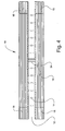
- cartridge (21) includes shell (20) and unitized structure (19).
- the center tube (12) has a plurality of perforations (14) and a flow-diverting baffle (34).
- Hollow fiber fabric (16) is wound around center tube (12), and tube sheets (18) are located at each of the lateral ends of hollow fiber fabric (16).
- Shell (20) surrounds the unitized structure (19), and a second potting material (38) forms an interlocking seal therebetween shell (20) and unitized structure (19).
- a liquid for example laden with an entrained gas, is introduced to hollow fiber contactor (10) via port (24) in a fluid communication with tube (12).
- the liquid exits tube (12) via perforations (14), travels over the exterior surface of the hollow fibers of hollow fiber fabric (16), and exits contactor (10) via port (26) after reentering tube (12).
- Ports (28) are coupled with a vacuum and/or sweep gas source and are in fluid communication with the lumen side of the hollow fibers of the hollow fiber fabric (16).
- vacuum drawn on the lumen side of the hollow fibers of the hollow fiber fabric (16) provides the driving force for the diffusion of the gas from the liquid to lumen side of the hollow fibers of the hollow fiber fabric (16) where it is exhausted via ports 28.
- shell (20) may have any shape. Such shapes may be selected from the group consisting of a cylindrical shape, a rectangular shape, and combinations thereof.
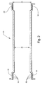
- Shell (20) includes an internal bonding surface (30). Internal bonding surface (30), as used herein, is defined as the interior surface of the lateral ends of shell (20). Shell (20) may or may not have flanged ends on either side, as shown in figs. 1, 2, and 5.
- Shell (20) may have any diameter.
- shell (20) has a diameter (36) greater than 6 inches. More preferably, shell (20) has a diameter (36) of at least 10 inches.
- the diameter (40) of shell (20) at its lateral ends, which defines the internal bonding surface (30), may be greater or less than the shell diameter (36).
- diameter (40) is constant over the internal bonding surface (30), but it may vary, e.g. outwardly flared, or inwardly reduced.
- An interlocking geometry ring (32) is provided on internal bonding surface (30).
- Ring (32) may have various longitudinal cross-sectional shapes, disclosed below. There must be at least one ring (32); however, multiple rings (32) are also possible. Different methods may be employed to provide ring (32) on internal bonding surface (30). These methods include, but are not limited to, welding or gluing. In the alternative, ring (32) may be an integral component of internal bonding surface (30), i.e. ring (32) may be cut into the internal bonding surface (30). Regardless of which method being employed to provide ring (32) on internal bonding surface (30), the point of attachment of ring (32) to internal bonding surface (30) may have any width.
- the point of attachment of ring (32) to internal bonding surface (30) is at least 0.4 inch (1.0 cm) wide.
- the width of the point of attachment of ring (32) to internal bonding surface (30) is important in maintaining the seal between shell (20) and the unitized structure (19) because it is the potential shear stress-induced line of failure under shell side pressure loading.
- interlocking geometry ring (32) may have various longitudinal cross-sectional shapes. These shapes include a dovetail-shaped design (3a), a left wedge-shaped design (3b), a right wedge-shaped design (3c), a dovetail-shaped design with an extension arm (3d), a left wedge-shaped design with an extension arm (3e), a right wedge-shaped design with an extension arm (3f), a spearhead-shaped design (3g), a left semi-spearhead-shaped design (3h), a right semi-spearhead-shaped design (3i), a circular-shaped design (3j), a left-semi-circular-shaped design (3k), a right-semi-circular-shaped design (3I), or combinations thereof.
- unitized structure (19) includes center tube (12), hollow fiber fabric (16), and tube sheets (18).
- the center tube (12) may be made of any material, which possesses sufficient mechanical strength to provide the desired support for the hollow fiber fabric 16, and tube sheets (18).
- the center tube (12) may be comprised of a plastic such as polypropylene, polyethylene, polyvinyl chloride, polyvinylidene fluoride, or ABS (Acrylonitrile- butadiene-Styrene), a composite material, or a metal.
- center tube (12) includes plurality of perforations (14), and flow diverting baffle (34).
- Hollow fiber fabric (16) may be constructed using processes well known in the art. Generally, in hollow fiber fabric construction, the hollow fiber membranes are formed into a bundle with a suitable shape for hollow fiber fabric construction. Preferred bundle arrangements include parallel laying down of fibers or bias wrap laying down of fibers.
- the hollow fibers of hollow fiber fabric (16) are any membranes suitable for use in diffusion operations. See Kesting, R. E., Synthetic Polymeric Membranes, 2 nd ed., John Wiley & Sons, New York, N.Y., (1985), incorporated herein by reference.
- the hollow fiber membranes may be made of synthetic polymers, cellulose, or synthetically modified cellulose.
- Synthetic polymers include, but are not limited to, polyethylene, polypropylene, polybutylene, poly (isobutylene), poly (methyl pentene), polysulfone, polyethersulfone, polyester, polyetherimide, polyacrylnitril, polyamide, polymethylmethacrylate (PMMA), ethylenevinyl alcohol, and fluorinated polyolefins.
- the hollow fiber membranes are made of polyolefin. Examples include, but are not limited to, microporous polyolefin membranes, commercially available under the name of CELGARD® hollow fibers from Celgard Inc. of Charlotte, N.C. or asymmetric membranes from Dainippon Ink and Chemicals of Tokyo, Japan, see U.S. Pat. No. 4,664,681 incorporated herein by reference.
- Spacer may be used to maintain the space between the layers of the wound hollow fiber fabric (16), so that fluid may be evenly distributed over the entire surface of all the hollow fibers. This distribution is important to maximize removal efficiency of the contactor. See U.S. Pat. No. 4,940,617.
- Tube sheets (18) are located at each end of the hollow fiber fabric (16).
- the tube sheets (18) are cylindrical in longitudinal cross-section with sufficient thickness to provide support for the hollow fiber fabric (16) and to withstand the pressures exerted on the tube sheets (18) during operation.
- the tube sheets (18) function to hold the hollow fiber fabric (16) in place and to partition the contactor (10) into a shell side passageway and a lumen side passageway.
- the tube sheets (18) may be comprised of first potting materials.
- hollow fiber fabric (16) is wound around the center tube (12), and first potting materials are laid at the lateral edges of the hollow fiber (16) to form tube sheets (18).
- First potting materials should be capable of forming a fluid tight seal around the hollow fiber membranes. It is preferable that first potting materials be capable of bonding to the center tube (12) and/or shell (20) as well as the hollow fiber fabric (16).
- First potting materials may be thermosetting materials or thermoplastic materials.
- Thermosetting materials include, but are not limited to, epoxy, and polyurethane. Epoxies are preferred.
- Thermoplastics refers to a high polymer that softens when exposed to heat and returns to its original condition when cooled to room temperature; the term is usually applied to synthetics such as polyvinyl chloride, nylons, fluorocarbon polymers, linear polyethylene, polyurethane prepolymer, polystyrene, polypropylene, and cellulosic and acrylic resins.
- Exemplary thermoplastics include polyolefins, such as polypropylene and polyethylene.
- Different potting methods may be employed to complete the first potting step.
- Different potting methods include, but are not limited to, bead potting, centrifugal potting, mold potting, and gravity potting.
- the hollow fiber fabric (16) is inserted into shell (20), the assembly is then spun on its midpoint to create centrifugal force at both ends of the hollow fiber fabric (16), first potting material are introduced into the shell-side space near both ends of the hollow fiber fabric (16), and the first potting material is allowed to cure.
- the first potting material is introduced into each end of the vertically mounted hollow fiber fabric (16), one at a time, and allowed to settle into the end of the hollow fiber fabric (16) and cure.
- the hollow fiber fabric (16) is placed in a mold, and the mold is filled with the first potting material to a desired depth.
- the hollow fiber fabric (16) is retained in filled mold until first potting material hardens.
- the unitized structure (19) is disposed within shell (20).
- Shell (20) functions to protect the outside of the unitized structure (19) from damage and to contain or seal the unitized structure (19) from the outside environment.
- Shell (20) is arranged about the tube sheets in such a fashion that an interlocking seal is formed between the first tube sheet (18) and shell (20), and the second tube sheet (18) and shell (20), such that fluid cannot communicate across or through the interlocking seal.
- contactor (10) is partitioned into a shell side passageway and a lumen side passageway.
- tube sheets (18) are bonded directly to shell (20) with a second potting material (38), which bonds tube sheets (18) to shell (20) at the interlocking geometry ring (32) to form the interlocking seal.
- the interlocking geometry ring (32) enhances the mechanical strength of the interlocking seal between tube sheets (18) and shell (20) in multiple directions during the expansions and contractions of the potted materials.
- Second potting materials (38) may be thermosetting materials or thermoplastic materials. Second potting materials (38) may be the same material as the first potting material, as described hereinabove. It is preferable that second potting materials (38) be capable of bonding to tube sheets (18) and shell (20) at the interlocking geometry ring (32).
- Thermosetting materials include, but are not limited to, epoxy, and polyurethane. Epoxies are preferred.
- Thermoplastics refers to a high polymer that softens when exposed to heat and returns to its original condition when cooled to room temperature; the term is usually applied to synthetics such as polyvinyl chloride, nylons, fluorocarbon polymers, linear polyethylene, polyurethane prepolymer, polystyrene, polypropylene, and cellulosic and acrylic resins.
- Exemplary thermoplastics include polyolefins, such as polypropylene and polyethylene.
- Different potting methods may be employed to complete the second potting step.
- Different potting methods include, but are not limited to, mold potting, centrifugal potting, and gravity potting.
- the unitized structure (19) is inserted into shell (20), and that structure is inserted into a mold.
- Second potting materials (38) are injected through the mold, into the space between shell (20) and tube sheet (18). The potting materials (38) are allowed to solidify, and form the interlocking seal therebetween the tube sheets (18) and shell (20).
- the cartridge (21) is, then, removed from the mold.
- the ends are, preferably, subjected to a rotary cut to open the end of the hollow fibers and to generate a planar cut surface that is perpendicular to the centerline of the cartridge (21).
- the cartridge (21) may be heat-treated. Heat-treatment increases the thermal/mechanical integrity of the cartridge (21) by reducing residual stress. Heat-treating is, preferably, for a period of time sufficient for the cartridge to come to thermal equilibrium.
- End caps (22) are adjoined to cartridge (21) to form contactor (10).
- End caps 22 are preferably made of thermoplastic or composite materials.
- the adjoining of the end caps (22) to the cartridge (21) can be achieved by means selected from the group consisting of butt-welding techniques, lap-welding techniques, solvent welding techniques, thermal welding techniques, bolted flange joints, and joints induced by infrared or ultrasonic methods.
- ports may vary, so long as the integrity of the shell side passageway and the lumen side passageway is maintained.
- Port (24) is a feed inlet means, it is generally a port, nozzle, fitting or other opening which allows introduction of mixture fluids, which is to be separated, into a hollow fiber membrane contactor.
- Port (26) is a non-permeate outlet means, which is adapted for removing the fluids, which do not permeate through the hollow fiber membranes.
- Port (26) is generally a port, nozzle, fitting, or other opening, which allows the removal of the non-permeate from the hollow fiber membrane contactor.
- Ports (28) are permeate outlet means for removing fluid, which permeate through the hollow fiber membrane. Ports (28) are generally a port, nozzle, fitting, or other opening adapted for withdrawing the permeate.
Landscapes
- Chemical & Material Sciences (AREA)
- Chemical Kinetics & Catalysis (AREA)
- Engineering & Computer Science (AREA)
- Manufacturing & Machinery (AREA)
- Separation Using Semi-Permeable Membranes (AREA)
- Degasification And Air Bubble Elimination (AREA)
Applications Claiming Priority (2)
| Application Number | Priority Date | Filing Date | Title |
|---|---|---|---|
| US10/793,573 US7264725B2 (en) | 2004-03-04 | 2004-03-04 | Hollow fiber membrane contactor and method of making same |
| US793573 | 2004-03-04 |
Publications (1)
| Publication Number | Publication Date |
|---|---|
| EP1570896A1 true EP1570896A1 (de) | 2005-09-07 |
Family
ID=34750632
Family Applications (1)
| Application Number | Title | Priority Date | Filing Date |
|---|---|---|---|
| EP05003822A Withdrawn EP1570896A1 (de) | 2004-03-04 | 2005-02-23 | Stoffaustauschapparat mit Hohlfasermembranen und Verfahren zu dessen Herstellung |
Country Status (5)
| Country | Link |
|---|---|
| US (1) | US7264725B2 (de) |
| EP (1) | EP1570896A1 (de) |
| JP (1) | JP2005246379A (de) |
| CN (1) | CN100346870C (de) |
| TW (1) | TWI279250B (de) |
Cited By (3)
| Publication number | Priority date | Publication date | Assignee | Title |
|---|---|---|---|---|
| EP2437872A4 (de) * | 2009-06-05 | 2014-06-18 | Kolon Inc | Modulgehäuse und hohlfasermembranenmodul damit |
| EP2878362A1 (de) * | 2013-12-02 | 2015-06-03 | Gambro Lundia AB | Hohlfaserdialysatoren |
| WO2017088845A1 (de) * | 2015-11-25 | 2017-06-01 | Serumwerk Bernburg Ag | Hohlfasermembran-filtriervorrichtung und verfahren zur herstellung derselben |
Families Citing this family (59)
| Publication number | Priority date | Publication date | Assignee | Title |
|---|---|---|---|---|
| AUPR421501A0 (en) | 2001-04-04 | 2001-05-03 | U.S. Filter Wastewater Group, Inc. | Potting method |
| AUPR692401A0 (en) | 2001-08-09 | 2001-08-30 | U.S. Filter Wastewater Group, Inc. | Method of cleaning membrane modules |
| AU2004289373B2 (en) | 2003-11-14 | 2010-07-29 | Evoqua Water Technologies Llc | Improved module cleaning method |
| WO2005092799A1 (en) | 2004-03-26 | 2005-10-06 | U.S. Filter Wastewater Group, Inc. | Process and apparatus for purifying impure water using microfiltration or ultrafiltration in combination with reverse osmosis |
| WO2006026814A1 (en) | 2004-09-07 | 2006-03-16 | Siemens Water Technologies Corp. | Reduction of backwash liquid waste |
| JP4896025B2 (ja) | 2004-09-14 | 2012-03-14 | シーメンス・ウォーター・テクノロジーズ・コーポレイション | 膜モジュールから固形分を除去するための方法および装置 |
| EP1838422A4 (de) | 2004-12-24 | 2009-09-02 | Siemens Water Tech Corp | Einfaches gasspülverfahren und entsprechende vorrichtung |
| CN101184548B (zh) | 2005-04-29 | 2011-10-05 | 西门子水技术公司 | 用于膜滤器的化学清洗剂 |
| JP2009504399A (ja) | 2005-08-22 | 2009-02-05 | シーメンス・ウォーター・テクノロジーズ・コーポレーション | 管状マニホールドを使用して逆洗を最小化する水濾過のためのアセンブリ |
| US7682421B2 (en) * | 2006-10-12 | 2010-03-23 | Celgard Llc | Degassing a liquid using a gravity fed apparatus |
| WO2008123972A1 (en) | 2007-04-02 | 2008-10-16 | Siemens Water Technologies Corp. | Improved infiltration/inflow control for membrane bioreactor |
| US9764288B2 (en) | 2007-04-04 | 2017-09-19 | Evoqua Water Technologies Llc | Membrane module protection |
| US8066801B2 (en) * | 2007-04-24 | 2011-11-29 | New York Air Brake Corporation | Sweep air system for membrane air dryer |
| AU2008263139B2 (en) | 2007-05-29 | 2011-08-25 | Evoqua Water Technologies Llc | Membrane cleaning with pulsed airlift pump |
| US8517086B2 (en) * | 2008-02-29 | 2013-08-27 | Caterpillar Inc. | Composite heat exchanger end structure |
| JP5354248B2 (ja) * | 2008-03-05 | 2013-11-27 | Nok株式会社 | 加湿膜モジュール |
| US20110126707A1 (en) * | 2008-03-07 | 2011-06-02 | Vaperma Inc. | Emission treatment process from natural gas dehydrators |
| US20090277826A1 (en) * | 2008-05-08 | 2009-11-12 | Pedersen Steven K | Hollow fibre membrane module |
| JP2013500144A (ja) | 2008-07-24 | 2013-01-07 | シーメンス インダストリー インコーポレイテッド | 濾過システムにおける濾過膜モジュールアレイに対して構造的支持を施すための方法および濾過システム |
| NZ591259A (en) | 2008-08-20 | 2013-02-22 | Siemens Industry Inc | A hollow membrane filter backwash system using gas pressurised at at least two pressures feed from the down stream side to push water through the filter to clean it |
| JP5061064B2 (ja) * | 2008-08-26 | 2012-10-31 | ダイセン・メンブレン・システムズ株式会社 | 中空糸型膜モジュール |
| EA201100751A1 (ru) * | 2008-11-13 | 2011-12-30 | Уайт Фокс Текнолоджиз Лтд. | Способ уплотнения мембранных модулей |
| US8333892B2 (en) * | 2009-04-02 | 2012-12-18 | Spintek Filtration, Inc. | Quick connect modular water purification system |
| AU2010101488B4 (en) | 2009-06-11 | 2013-05-02 | Evoqua Water Technologies Llc | Methods for cleaning a porous polymeric membrane and a kit for cleaning a porous polymeric membrane |
| US8506685B2 (en) * | 2009-08-17 | 2013-08-13 | Celgard Llc | High pressure liquid degassing membrane contactors and methods of manufacturing and use |
| ES2738898T3 (es) * | 2010-04-30 | 2020-01-27 | Evoqua Water Tech Llc | Dispositivo de distribución de flujo de fluido |
| CN102382677B (zh) * | 2010-08-25 | 2013-11-27 | 中国石油化工股份有限公司 | 一种脱除烃油中环丁砜的方法 |
| AU2011305377B2 (en) | 2010-09-24 | 2014-11-20 | Evoqua Water Technologies Llc | Fluid control manifold for membrane filtration system |
| WO2012170956A1 (en) * | 2011-06-08 | 2012-12-13 | Benjamin Bikson | Hollow fiber apparatus and use thereof for fluids separations and heat and mass transfers |
| CN102366706A (zh) * | 2011-06-29 | 2012-03-07 | 苏州顶裕水务科技有限公司 | 一种中空纤维超滤膜组件用的扇形盖帽 |
| CN103958034B (zh) | 2011-09-30 | 2017-03-22 | 伊沃夸水处理技术有限责任公司 | 隔离阀 |
| CA2850309C (en) | 2011-09-30 | 2020-01-07 | Evoqua Water Technologies Llc | Improved manifold arrangement |
| US9533261B2 (en) | 2012-06-28 | 2017-01-03 | Evoqua Water Technologies Llc | Potting method |
| AU2013231145B2 (en) | 2012-09-26 | 2017-08-17 | Evoqua Water Technologies Llc | Membrane potting methods |
| CN104684631A (zh) | 2012-09-26 | 2015-06-03 | 伊沃夸水处理技术有限责任公司 | 膜固定设备 |
| EP2900356A1 (de) | 2012-09-27 | 2015-08-05 | Evoqua Water Technologies LLC | Gaswäscher für tauchmembranen |
| CN103877869A (zh) * | 2012-12-19 | 2014-06-25 | 中国科学院大连化学物理研究所 | 聚四氟乙烯中空纤维多孔膜及其制备和在膜接触器中应用 |
| EP3052221B1 (de) | 2013-10-02 | 2022-12-14 | Rohm & Haas Electronic Materials Singapore Pte. Ltd | Vorrichtung zur reparatur eines membranfiltrationsmoduls |
| WO2015134408A1 (en) | 2014-03-03 | 2015-09-11 | Blue Planet, Ltd. | Alkali enrichment mediated co2 sequestration methods, and systems for practicing the same |
| WO2015178892A1 (en) * | 2014-05-20 | 2015-11-26 | Texas State University | Fluidic system for high throughput preparation of microparticles and nanoparticles |
| EP3204145A4 (de) | 2014-10-09 | 2018-06-27 | Blue Planet Ltd. | Verfahren zur kontinuierlichen herstellung von kohlenstoffsequestrierungsmaterial und systeme zur durchführung davon |
| EP3310464B1 (de) | 2015-06-22 | 2025-02-12 | Solventum Intellectual Properties Company | Einzelschweisskontaktor |
| WO2017011068A1 (en) | 2015-07-14 | 2017-01-19 | Evoqua Water Technologies Llc | Aeration device for filtration system |
| EP3290100B1 (de) * | 2016-08-31 | 2020-08-19 | Gambro Lundia AB | Diffusions- und/oder filtrationsvorrichtung |
| TWI609777B (zh) * | 2017-03-14 | 2018-01-01 | Li Qing Cheng | 彈性墊體製造方法 |
| EP3412357A1 (de) * | 2017-05-29 | 2018-12-12 | Asahi Kasei Kabushiki Kaisha | Hohlfasermembranmodul |
| DE102017006238A1 (de) * | 2017-07-03 | 2019-01-03 | Enmodes Gmbh | Vorrichtung für den Stoffaustausch zwischen zwei Fluiden, Verfahren zu dessen Herstellung, sowie Wickel und Kernanordnung hierfür |
| US10758844B2 (en) * | 2017-07-25 | 2020-09-01 | Hamilton Sundstrand Corporation | Fluid degassing devices having selected profiles |
| CN108176234B (zh) * | 2017-12-28 | 2021-07-20 | 德蓝水技术股份有限公司 | 一种复合式膜组件及其制备方法 |
| AU2020210754A1 (en) | 2019-01-23 | 2021-07-08 | Blue Planet Systems Corporation | Carbonate aggregate compositions and methods of making and using the same |
| EP3925691A1 (de) * | 2020-06-18 | 2021-12-22 | Gambro Lundia AB | Diffusionsvorrichtung |
| US11491464B1 (en) | 2021-06-24 | 2022-11-08 | Avanpore LLC | Mesoporous poly (aryl ether ketone) hollow fiber membranes and use thereof in mass transfer processes |
| CA3226562A1 (en) | 2021-08-23 | 2023-03-02 | Parker-Hannifin Corporation | Fuel cell humidificaton potting adhesive shroud |
| CN118401285A (zh) * | 2021-12-15 | 2024-07-26 | 恩特格里斯公司 | 具有改进冲洗的过滤器的方法及系统 |
| CN118647588A (zh) | 2021-12-20 | 2024-09-13 | 蓝色星球系统公司 | 生产建筑材料的方法 |
| TW202330077A (zh) * | 2021-12-28 | 2023-08-01 | 日商Dic股份有限公司 | 脫氣模組及液體的脫氣方法 |
| US20240416286A1 (en) * | 2023-05-15 | 2024-12-19 | KMX Technologies, Inc | Membrane bundle for vacuum membrane distillation and method for making same |
| WO2026053703A1 (ja) * | 2024-09-05 | 2026-03-12 | Dic株式会社 | 中空糸膜エレメント、中空糸膜モジュール、脱気方法、及びガス付加方法 |
| JP7827236B1 (ja) * | 2024-09-05 | 2026-03-10 | Dic株式会社 | 中空糸膜エレメント、中空糸膜モジュール、脱気方法、及びガス付加方法 |
Citations (1)
| Publication number | Priority date | Publication date | Assignee | Title |
|---|---|---|---|---|
| EP1256372A2 (de) * | 2001-05-08 | 2002-11-13 | Celgard Inc. | Stoffaustauschapparat mit Hohfasermembranen und Verfahren zu dessen Herstellung |
Family Cites Families (23)
| Publication number | Priority date | Publication date | Assignee | Title |
|---|---|---|---|---|
| US9942A (en) * | 1853-08-16 | Tbip-hammer | ||
| DE123476C (de) * | 1960-09-19 | |||
| GB1366615A (en) * | 1971-02-25 | 1974-09-11 | Dow Chemical Co | Method for making a hollow fibre separatory element |
| US4220535A (en) * | 1978-08-04 | 1980-09-02 | Monsanto Company | Multi-zoned hollow fiber permeator |
| JPS59196706A (ja) * | 1983-04-22 | 1984-11-08 | Dainippon Ink & Chem Inc | 不均質膜およびその製造方法 |
| JPS6119404U (ja) * | 1984-07-10 | 1986-02-04 | ダイセル化学工業株式会社 | モジユ−ル構造体 |
| DE3803693A1 (de) * | 1987-03-10 | 1988-09-22 | Akzo Gmbh | Mehrlagiger hohlfadenwickelkoerper |
| SE465095B (sv) * | 1988-07-07 | 1991-07-22 | Gambro Dialysatoren | Taetning innefattande en ring av ett flexibelt material avsedd att pressas mellan tvaa parallella, foeretraedesvis slaeta taetningsytor |
| JPH0347271A (ja) * | 1989-07-14 | 1991-02-28 | Terumo Corp | 液体処理器 |
| FR2670301B1 (fr) * | 1990-12-07 | 1993-02-12 | Merlin Gerin | Dispositif de detection neutronique a dynamique etendue pour le controle et la commande des reacteurs nucleaires. |
| US5449457A (en) * | 1991-04-22 | 1995-09-12 | Hoechst Celanese Corporation | Liquid membrane modules with minimal effective membrane thickness and methods of making the same |
| US5186832A (en) * | 1991-12-31 | 1993-02-16 | Hoechst Celanese Corporation | Spiral-wound hollow fiber membrane fabric cartridges and modules having integral turbulence promoters |
| US5264171A (en) * | 1991-12-31 | 1993-11-23 | Hoechst Celanese Corporation | Method of making spiral-wound hollow fiber membrane fabric cartridges and modules having flow-directing baffles |
| US5284584A (en) * | 1992-12-31 | 1994-02-08 | Hoechst Celanese Corporation | Hollow fiber membrane fabric - containing cartridges and modules having solvent-resistant thermoplastic tube sheets, and methods for making the same |
| JPH06296834A (ja) * | 1993-04-20 | 1994-10-25 | Kanegafuchi Chem Ind Co Ltd | 中空糸型フィルター |
| JPH08229359A (ja) * | 1995-02-28 | 1996-09-10 | Kanegafuchi Chem Ind Co Ltd | 中空糸膜型ろ過モジュールの製造方法 |
| JPH09253631A (ja) * | 1996-03-27 | 1997-09-30 | Kanegafuchi Chem Ind Co Ltd | 水処理装置 |
| US5695545A (en) * | 1996-05-10 | 1997-12-09 | Hoechst Celanese Corporation | Degassing liquids: apparatus and method |
| JPH10165777A (ja) * | 1996-12-13 | 1998-06-23 | Toray Ind Inc | 中空糸モジュールおよびその製造方法 |
| US6207053B1 (en) * | 1998-03-12 | 2001-03-27 | Celgard Inc. | Thermoplastic, unibody transfer device |
| US6616841B2 (en) * | 2001-06-21 | 2003-09-09 | Celgard Inc. | Hollow fiber membrane contactor |
| US7316718B2 (en) | 2001-07-11 | 2008-01-08 | Millennium Cell, Inc. | Differential pressure-driven borohydride based generator |
| CA2431765C (en) * | 2001-11-05 | 2007-02-20 | Asahi Kasei Kabushiki Kaisha | Hollow fiber membrane module |
-
2004
- 2004-03-04 US US10/793,573 patent/US7264725B2/en not_active Expired - Lifetime
-
2005
- 2005-01-31 TW TW094102936A patent/TWI279250B/zh not_active IP Right Cessation
- 2005-02-23 EP EP05003822A patent/EP1570896A1/de not_active Withdrawn
- 2005-03-03 CN CNB2005100518740A patent/CN100346870C/zh not_active Expired - Fee Related
- 2005-03-04 JP JP2005060065A patent/JP2005246379A/ja active Pending
Patent Citations (1)
| Publication number | Priority date | Publication date | Assignee | Title |
|---|---|---|---|---|
| EP1256372A2 (de) * | 2001-05-08 | 2002-11-13 | Celgard Inc. | Stoffaustauschapparat mit Hohfasermembranen und Verfahren zu dessen Herstellung |
Cited By (3)
| Publication number | Priority date | Publication date | Assignee | Title |
|---|---|---|---|---|
| EP2437872A4 (de) * | 2009-06-05 | 2014-06-18 | Kolon Inc | Modulgehäuse und hohlfasermembranenmodul damit |
| EP2878362A1 (de) * | 2013-12-02 | 2015-06-03 | Gambro Lundia AB | Hohlfaserdialysatoren |
| WO2017088845A1 (de) * | 2015-11-25 | 2017-06-01 | Serumwerk Bernburg Ag | Hohlfasermembran-filtriervorrichtung und verfahren zur herstellung derselben |
Also Published As
| Publication number | Publication date |
|---|---|
| US20050194305A1 (en) | 2005-09-08 |
| JP2005246379A (ja) | 2005-09-15 |
| TW200602119A (en) | 2006-01-16 |
| US7264725B2 (en) | 2007-09-04 |
| CN100346870C (zh) | 2007-11-07 |
| CN1680006A (zh) | 2005-10-12 |
| TWI279250B (en) | 2007-04-21 |
Similar Documents
| Publication | Publication Date | Title |
|---|---|---|
| US7264725B2 (en) | Hollow fiber membrane contactor and method of making same | |
| US7638049B2 (en) | Three-port high performance mini hollow fiber membrane contactor | |
| US4767426A (en) | Membrane filter tube and method of preparation | |
| US5114582A (en) | Filter element and spiral-wound membrane cartridge containing same | |
| KR102532833B1 (ko) | 유체의 분리를 위한 중공 사막 카트리지 및 모듈 | |
| JP3374262B2 (ja) | 濾液を流すための濾液導管を区切るチューブ | |
| US7641795B2 (en) | Membrane contactor | |
| JP3229660B2 (ja) | スパイラル状巻回半透性膜カートリッジ並びにその製造方法及び一体型分離装置 | |
| CN111514759A (zh) | 中空纤维膜模块和用于制造中空纤维膜模块的方法 | |
| KR20220014890A (ko) | 튜브형 멤브레인 열교환기 | |
| EP1256372A2 (de) | Stoffaustauschapparat mit Hohfasermembranen und Verfahren zu dessen Herstellung | |
| JPH08332306A (ja) | 脱気用膜及び脱気モジュール | |
| US6352641B1 (en) | Wound pocket module | |
| JP2012183464A (ja) | 流体分離素子用テレスコープ防止板および流体分離素子 | |
| US12337282B2 (en) | Potted flat sheet membrane filtration module | |
| GB2189404A (en) | Fluid filter element | |
| JP2003275544A (ja) | スパイラル型膜エレメント及びその製造方法 | |
| KR101629613B1 (ko) | 중공사막 모듈 및 그 제조방법 | |
| JP6610061B2 (ja) | 中空糸膜モジュール | |
| JPH03135422A (ja) | 中空糸膜モジュール及び中空糸膜モジュール用中空糸束 | |
| JPH04247223A (ja) | 中空糸膜モジュール | |
| JP5385523B2 (ja) | 分離膜モジュールの製造方法 | |
| WO2017070775A1 (en) | Potted flat sheet membrane filtration module | |
| CA2308234A1 (en) | Gel potting method for filtering hollow fibre membranes | |
| JPH0824589A (ja) | 中空糸膜モジュール |
Legal Events
| Date | Code | Title | Description |
|---|---|---|---|
| PUAI | Public reference made under article 153(3) epc to a published international application that has entered the european phase |
Free format text: ORIGINAL CODE: 0009012 |
|
| AK | Designated contracting states |
Kind code of ref document: A1 Designated state(s): AT BE BG CH CY CZ DE DK EE ES FI FR GB GR HU IE IS IT LI LT LU MC NL PL PT RO SE SI SK TR |
|
| AX | Request for extension of the european patent |
Extension state: AL BA HR LV MK YU |
|
| 17P | Request for examination filed |
Effective date: 20060107 |
|
| AKX | Designation fees paid |
Designated state(s): DE FR GB IT |
|
| STAA | Information on the status of an ep patent application or granted ep patent |
Free format text: STATUS: THE APPLICATION HAS BEEN WITHDRAWN |
|
| 18W | Application withdrawn |
Effective date: 20091029 |