EP1570934A2 - Machine à nettoyer des coins pour fenêtres ou portes - Google Patents
Machine à nettoyer des coins pour fenêtres ou portes Download PDFInfo
- Publication number
- EP1570934A2 EP1570934A2 EP05003005A EP05003005A EP1570934A2 EP 1570934 A2 EP1570934 A2 EP 1570934A2 EP 05003005 A EP05003005 A EP 05003005A EP 05003005 A EP05003005 A EP 05003005A EP 1570934 A2 EP1570934 A2 EP 1570934A2
- Authority
- EP
- European Patent Office
- Prior art keywords
- processing
- machining
- tools
- frame
- units
- Prior art date
- Legal status (The legal status is an assumption and is not a legal conclusion. Google has not performed a legal analysis and makes no representation as to the accuracy of the status listed.)
- Withdrawn
Links
Images


Classifications
-
- B—PERFORMING OPERATIONS; TRANSPORTING
- B23—MACHINE TOOLS; METAL-WORKING NOT OTHERWISE PROVIDED FOR
- B23C—MILLING
- B23C3/00—Milling particular work; Special milling operations; Machines therefor
- B23C3/12—Trimming or finishing edges, e.g. deburring welded corners
- B23C3/128—Trimming or finishing edges of doors and windows
Definitions
- the invention relates to a corner brushing device for made of profiled bars welded window or door frame with at least two across a conveyor track for the frame relative to each other adjustable machining units, on which editing tools for editing the Corner joints of the frame are arranged.
- the invention relates to a method for processing Window or door frame with such Corner cleaning device.
- Such a corner plastering machine is for example from the EP 0 325 264 A1.
- Machining tools of the opposite Machining units symmetrical to the one between the two Processing units extending central axis arranged.
- the invention has the object, a Eckenverputzvorraum of the type mentioned in the effect educate that with simple constructive means a Processing of window and door frames, even with very small dimensions is possible, with the simultaneous use of both Processing units.
- the at least two corresponding ones Editing tools for editing the respective Outside corner of the frame for example.
- a contour cutter formed Due to the arrangement of the disc contour cutter in the zu pointing to the workpiece to be machined front area of the Tool carrier of a processing unit and the Arrangement of the disk contour cutter of the opposite one Machining unit in the rear area of the tool carrier directed away from the workpiece, can be very small dimensions of Window and profile frames also in so-called two-head operation edit what the tact time when editing a Window frame significantly shortened.
- corresponding processing tools of at least two Processing units in the transverse direction of the conveyor track in the same sequence of the associated tool carriers are located. This makes it possible for each one corresponding processing tools of the two Machining units at the opposite corners of the Window or door frame used. Overall leaves This causes the programming effort for the method of Considerably reduce machining units.
- the at least two processing units each two spaced apart arranged tool carrier with machining tools have, with each other corresponding Machining tools on the two tool carriers each Processing unit mirror symmetric to the plane of Conveyor are arranged. Due to the shortened Travels for the processing of the two visible surfaces of the Frame can shorten the cycle time again.
- each of both opposite each other across the conveyor track Machining units only one machining tool for each Processing of the respective frame corner, in particular one Disc milling has.
- the two processing units at least transversely to the conveyor track relative to each other movable be.
- a processing unit for example, fixed be arranged while the second processing unit is transverse can be moved to the conveying direction.
- the at least two processing units each by one Axis in and out of the machining position with the respective compassioneck are formed pivotable.
- a Production line can then by pivoting and corresponding delivery of the processing units the opposite frame corners of the leading frame and of the trailing frame.
- the editing tools to the respective Tool holders in and out of the machining position for the respective compassioneck adjustable, eg. Swiveling and / or movable are. This can, for example, by a linear movement perpendicular to the frame plane and / or by pivoting the respective machining tool against the window or Door profile done.
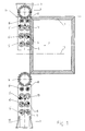
- corner cleaning devices shown in the drawing Serve at the corners of plastic or plastic Metal profile bars butt welded window or door frame 1 to be removed welding beads. In the process, they become too processing frame 1 on a not shown Conveyor conveyed in the direction of arrow 2.
- the Machining units 3, 4 have tool carriers 10, 11 in Shape of tool banks, which by means of not shown guides in the conveying direction, transverse to Conveying direction and are movable perpendicular thereto.
- the Processing units 3, 4 and their tool carrier 10, 11th have, for example, processing tools for indoor and Outside corner of the respective frame corner as well as for the Visible surfaces of the frame 1 on.
- Internal cornering tools 5 Visible surface processing tools 6, more Viewing surface processing tools 7, for another Profile type, drilling or milling units 8, for drilling the Sealing groove and outer corner contour milling cutter 9 for machining provided the respective compassionecks.
- the other editing tools are used 5 'to 8' the processing of other types of profiles and types or Workpiece systems. Due to the paired arrangement of Machining tools next to each other can be the Tool carrier 3, 4 build shorter, as if, for example, the individual Machining tools arranged in a row one behind the other would. This also serves the purpose of small dimensions of Window or door frame 1 to edit.
- each same processing tools come 5 to 9 of the two processing units 3, 4 in synchronism with Processing at the respective frame corner.
- the execution of the compassionecks takes place at the here shown Embodiment in that the two Processing units 3, 4 and their tool carrier 10, 11th rectified and synchronously.
- the delivery the processing tools 5 to 9 is thus rectified, while of course the actual editing movement of the individual processing tools 5 to 9 itself not must be rectified.
- the disc contour cutter is 9 at the one processing unit 3 to the inside pointing end of the tool carrier 10 while he at the opposite processing unit 4 at the outwardly facing end of the tool carrier 11 is located.
- a space-saving design is achieved.
- the disc contour cutter 9 is approximately in the middle of the two processing support 10, 11 are located would allow the embodiment shown here the Machining much smaller window or door frame 1.
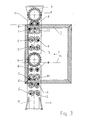
- the Machining units 3, 4 each two spaced from each other arranged tool carrier 10, 10 'and 11, 11' with Have editing tools.
- the Machining tools 5 to 8 can be the opposite visible surfaces of the frame 1 by short Infeed paths of the tools with a very short cycle time to edit.
- a disc contour cutter 9 for each processing unit 3, 4 is of course only a disc contour cutter 9 for each processing unit 3, 4 required.
- Embodiment according to Figure 16 are the Disk contour cutter 9 each processing unit 3, 4 to the upper tool carriers 10, 11 are arranged.
- the disc contour cutters 9 on the diagonally opposite tool carriers 11, 10 'according to Figure 17 are arranged.
- the two tool carriers 10, 10 'or 11, 11' of the two processing units 3, 4 independently movable.
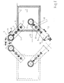
- FIGS. 6 to 10 show a corner brushing device in which the processing units 3, 4 perpendicular to the conveying plane Axes 16, 17 are formed pivotable.
- the Pivoting movement takes place so that the longitudinal axis of the Tool carrier 10, 11 on the miter of the two successive tapered profile pieces of the respective frame corner is aligned.
- a gradual Delivery of the processing units 3, 4 in Gehrungsraum To the individual processing tools 5 to 9 into working position, a gradual Delivery of the processing units 3, 4 in Gehrungsraum.
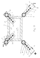
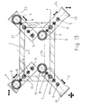
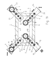
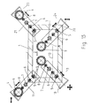
- FIGS. 11 to 15 is a so-called Four-head machine presented with a total of four Processing units 3, 4, 23, 24, which at the same time the Edit four corners of frame 1.
- the work sequence is similar to that of FIGS. 6 to 10, but with the pivotability of the processing units at this chosen embodiment for the sake of simplicity was waived.
Landscapes
- Engineering & Computer Science (AREA)
- Mechanical Engineering (AREA)
- Multi-Process Working Machines And Systems (AREA)
- Dovetailed Work, And Nailing Machines And Stapling Machines For Wood (AREA)
- Chain Conveyers (AREA)
Applications Claiming Priority (2)
| Application Number | Priority Date | Filing Date | Title |
|---|---|---|---|
| DE102004011340 | 2004-03-05 | ||
| DE200410011340 DE102004011340B4 (de) | 2004-03-05 | 2004-03-05 | Eckenputzvorrichtung für Fenster- oder Türrahmen |
Publications (2)
| Publication Number | Publication Date |
|---|---|
| EP1570934A2 true EP1570934A2 (fr) | 2005-09-07 |
| EP1570934A3 EP1570934A3 (fr) | 2009-10-21 |
Family
ID=34745434
Family Applications (1)
| Application Number | Title | Priority Date | Filing Date |
|---|---|---|---|
| EP05003005A Withdrawn EP1570934A3 (fr) | 2004-03-05 | 2005-02-12 | Machine à nettoyer des coins pour fenêtres ou portes |
Country Status (2)
| Country | Link |
|---|---|
| EP (1) | EP1570934A3 (fr) |
| DE (1) | DE102004011340B4 (fr) |
Cited By (2)
| Publication number | Priority date | Publication date | Assignee | Title |
|---|---|---|---|---|
| US7784161B2 (en) * | 2006-03-27 | 2010-08-31 | Rotox Gmbh | Device for machining the corner area of a frame welded together out of profiled pieces |
| CN104551681A (zh) * | 2014-12-22 | 2015-04-29 | 苏州市昌星模具机械有限公司 | 一种高效自动去毛刺整形装置 |
Families Citing this family (1)
| Publication number | Priority date | Publication date | Assignee | Title |
|---|---|---|---|---|
| DE102012004563A1 (de) * | 2012-03-09 | 2013-09-26 | Lissmac Maschinenbau Gmbh | Vorrichtung und Bearbeitungseinheit zur automatisierten Bearbeitung eines metallischen Werkstücks und Anbringvorrichtung |
Family Cites Families (4)
| Publication number | Priority date | Publication date | Assignee | Title |
|---|---|---|---|---|
| DE3801641C2 (de) * | 1988-01-21 | 1997-01-23 | Bernhard Eisenbach | Eckenputzmaschine für Fenster- oder Türrahmen |
| DE4237939C2 (de) * | 1992-11-11 | 1999-07-29 | Eisenbach B Rotox Gmbh | Eckenverputzvorrichtung mit drehbarem Werkzeugträger |
| EP0618032B1 (fr) * | 1993-03-31 | 1997-09-24 | Bernhard Eisenbach | Dispositif pour le traitement des joints d'angle de châssis fenêtre ou de porte en matière plastique soudés |
| DE10062842B4 (de) * | 2000-12-15 | 2006-02-16 | Rotox Gmbh B. Eisenbach | Vorrichtung zum Bearbeiten von Eckverbindungen |
-
2004
- 2004-03-05 DE DE200410011340 patent/DE102004011340B4/de not_active Expired - Fee Related
-
2005
- 2005-02-12 EP EP05003005A patent/EP1570934A3/fr not_active Withdrawn
Cited By (3)
| Publication number | Priority date | Publication date | Assignee | Title |
|---|---|---|---|---|
| US7784161B2 (en) * | 2006-03-27 | 2010-08-31 | Rotox Gmbh | Device for machining the corner area of a frame welded together out of profiled pieces |
| CN104551681A (zh) * | 2014-12-22 | 2015-04-29 | 苏州市昌星模具机械有限公司 | 一种高效自动去毛刺整形装置 |
| CN104551681B (zh) * | 2014-12-22 | 2017-07-18 | 苏州市昌星模具机械有限公司 | 一种高效自动去毛刺整形装置 |
Also Published As
| Publication number | Publication date |
|---|---|
| DE102004011340A1 (de) | 2005-09-22 |
| DE102004011340B4 (de) | 2007-01-18 |
| EP1570934A3 (fr) | 2009-10-21 |
Similar Documents
| Publication | Publication Date | Title |
|---|---|---|
| DE3823635C2 (fr) | ||
| EP3357617B1 (fr) | Dispositif d'usinage de profilé, ligne d'usinage de profilé et procédé | |
| EP0922547A2 (fr) | Dispositif pour la fabrication de châssis de fenêtres | |
| DE102007024589A1 (de) | Bearbeitungs-, insbesondere Geometrieschweißstation | |
| EP2070649B1 (fr) | Appareil de traitement de profilés | |
| DE19842386A1 (de) | Maschine und Verfahren zum Bearbeiten flacher Körper | |
| EP0605773B1 (fr) | Dispositif pour usiner les coins d'un cadre | |
| EP0771248B1 (fr) | Procede de production par usinage de profiles allonges de longueur definitive | |
| DE202015101311U1 (de) | Bearbeitungsstation zum Bearbeiten von Endlos-Metallprofilen | |
| DE4232289C2 (de) | Verfahren und Vorrichtung zum Verschwenken eines Fensterrahmens im Bereich einer Eckenputzmaschine | |
| DE102007014532A1 (de) | Vorrichtung zum Bearbeiten des Eckbereichs von aus Profilstücken geschweißten Rahmen | |
| DE602006000992T2 (de) | Maschine zur Herstellung von Türrahmen | |
| DE102004011340B4 (de) | Eckenputzvorrichtung für Fenster- oder Türrahmen | |
| DE3141618C2 (de) | Walzgerüstwechselvorrichtung für Walzstraßen | |
| DE102007044457A1 (de) | Drehmaschine | |
| DE19612251C1 (de) | Vorrichtung zur Bearbeitung von Schweißraupen | |
| DE2648447A1 (de) | Werkzeugmaschine mit zwei revolvertrommeln | |
| DE102015209080B4 (de) | Bearbeitungsanordnung zur Bearbeitung von Baugruppenteilen einer Baugruppe an einer Bearbeitungsstation einer Fertigungsstraße | |
| DE102017204026A1 (de) | Verfahren und Vorrichtung zur Herstellung von Zahnstangen | |
| DE4130085C2 (de) | Verfahren und Vorrichtung zum Bearbeiten von Schweißraupen oder dergleichen an den Ecken eines Rahmens | |
| DE102004053501B3 (de) | Kaltwalzmaschine und Kaltwalzverfahren | |
| EP1160049B1 (fr) | Machine-outil | |
| DE2408250A1 (de) | Verfahren zum herstellen von kuechenmoebeln und vorrichtung | |
| DE9206470U1 (de) | Vorrichtung zur Nachbearbeitung von spangebend bearbeiteten Kantenstreifen | |
| DE10009681C2 (de) | Zapfenschneidsystem zum Bearbeiten der Enden von Rahmenhölzern durch Fräsen |
Legal Events
| Date | Code | Title | Description |
|---|---|---|---|
| PUAI | Public reference made under article 153(3) epc to a published international application that has entered the european phase |
Free format text: ORIGINAL CODE: 0009012 |
|
| AK | Designated contracting states |
Kind code of ref document: A2 Designated state(s): AT BE BG CH CY CZ DE DK EE ES FI FR GB GR HU IE IS IT LI LT LU MC NL PL PT RO SE SI SK TR |
|
| AX | Request for extension of the european patent |
Extension state: AL BA HR LV MK YU |
|
| PUAL | Search report despatched |
Free format text: ORIGINAL CODE: 0009013 |
|
| AK | Designated contracting states |
Kind code of ref document: A3 Designated state(s): AT BE BG CH CY CZ DE DK EE ES FI FR GB GR HU IE IS IT LI LT LU MC NL PL PT RO SE SI SK TR |
|
| AX | Request for extension of the european patent |
Extension state: AL BA HR LV MK YU |
|
| STAA | Information on the status of an ep patent application or granted ep patent |
Free format text: STATUS: THE APPLICATION IS DEEMED TO BE WITHDRAWN |
|
| 18D | Application deemed to be withdrawn |
Effective date: 20090901 |