EP1571040A2 - Annäherungsdetektion-System für ein Fahrzeug - Google Patents
Annäherungsdetektion-System für ein Fahrzeug Download PDFInfo
- Publication number
- EP1571040A2 EP1571040A2 EP05250990A EP05250990A EP1571040A2 EP 1571040 A2 EP1571040 A2 EP 1571040A2 EP 05250990 A EP05250990 A EP 05250990A EP 05250990 A EP05250990 A EP 05250990A EP 1571040 A2 EP1571040 A2 EP 1571040A2
- Authority
- EP
- European Patent Office
- Prior art keywords
- vehicle
- sensor
- detection system
- unit
- proximity detection
- Prior art date
- Legal status (The legal status is an assumption and is not a legal conclusion. Google has not performed a legal analysis and makes no representation as to the accuracy of the status listed.)
- Withdrawn
Links
- 238000001514 detection method Methods 0.000 title claims abstract description 20
- 230000005540 biological transmission Effects 0.000 claims abstract description 4
- 238000004891 communication Methods 0.000 claims description 9
- XLYOFNOQVPJJNP-UHFFFAOYSA-N water Substances O XLYOFNOQVPJJNP-UHFFFAOYSA-N 0.000 claims description 2
- 230000007246 mechanism Effects 0.000 description 4
- 230000000007 visual effect Effects 0.000 description 3
- 230000002411 adverse Effects 0.000 description 1
- 230000004075 alteration Effects 0.000 description 1
- 238000013459 approach Methods 0.000 description 1
- 235000019504 cigarettes Nutrition 0.000 description 1
- 238000010276 construction Methods 0.000 description 1
- 238000005516 engineering process Methods 0.000 description 1
- 238000000034 method Methods 0.000 description 1
- 238000012986 modification Methods 0.000 description 1
- 230000004048 modification Effects 0.000 description 1
- 230000008569 process Effects 0.000 description 1
- 230000004044 response Effects 0.000 description 1
Images


Classifications
-
- B—PERFORMING OPERATIONS; TRANSPORTING
- B60—VEHICLES IN GENERAL
- B60Q—ARRANGEMENT OF SIGNALLING OR LIGHTING DEVICES, THE MOUNTING OR SUPPORTING THEREOF OR CIRCUITS THEREFOR, FOR VEHICLES IN GENERAL
- B60Q9/00—Arrangement or adaptation of signal devices not provided for in one of main groups B60Q1/00 - B60Q7/00, e.g. haptic signalling
- B60Q9/002—Arrangement or adaptation of signal devices not provided for in one of main groups B60Q1/00 - B60Q7/00, e.g. haptic signalling for parking purposes, e.g. for warning the driver that his vehicle has contacted or is about to contact an obstacle
- B60Q9/004—Arrangement or adaptation of signal devices not provided for in one of main groups B60Q1/00 - B60Q7/00, e.g. haptic signalling for parking purposes, e.g. for warning the driver that his vehicle has contacted or is about to contact an obstacle using wave sensors
- B60Q9/006—Arrangement or adaptation of signal devices not provided for in one of main groups B60Q1/00 - B60Q7/00, e.g. haptic signalling for parking purposes, e.g. for warning the driver that his vehicle has contacted or is about to contact an obstacle using wave sensors using a distance sensor
-
- B—PERFORMING OPERATIONS; TRANSPORTING
- B60—VEHICLES IN GENERAL
- B60Q—ARRANGEMENT OF SIGNALLING OR LIGHTING DEVICES, THE MOUNTING OR SUPPORTING THEREOF OR CIRCUITS THEREFOR, FOR VEHICLES IN GENERAL
- B60Q1/00—Arrangement of optical signalling or lighting devices, the mounting or supporting thereof or circuits therefor
- B60Q1/26—Arrangement of optical signalling or lighting devices, the mounting or supporting thereof or circuits therefor the devices being primarily intended to indicate the vehicle, or parts thereof, or to give signals, to other traffic
- B60Q1/30—Arrangement of optical signalling or lighting devices, the mounting or supporting thereof or circuits therefor the devices being primarily intended to indicate the vehicle, or parts thereof, or to give signals, to other traffic for indicating rear of vehicle, e.g. by means of reflecting surfaces
- B60Q1/305—Indicating devices for towed vehicles
-
- B—PERFORMING OPERATIONS; TRANSPORTING
- B60—VEHICLES IN GENERAL
- B60Q—ARRANGEMENT OF SIGNALLING OR LIGHTING DEVICES, THE MOUNTING OR SUPPORTING THEREOF OR CIRCUITS THEREFOR, FOR VEHICLES IN GENERAL
- B60Q2900/00—Features of lamps not covered by other groups in B60Q
- B60Q2900/30—Lamps commanded by wireless transmissions
Definitions
- This invention relates to an electronic proximity detection system for use on vehicles to detect an object in the path of the vehicle.
- the technology provides proximity sensors that may be used in alternative placements on a vehicle to indicate distance between a vehicle and an object to assist with manoeuvres other than reversing.
- Reversing aids have been provided that utilized sensors placed on the rear of a vehicle and attached to some form of alarm within the cabin of the vehicle.
- existing systems are generally incorporated in new vehicles and hard wired into the vehicles such that they have no portability, retro-fitability and are redundant once any form of trailer, caravan or the item is towed behind the vehicle.
- existing systems would normally need to be disabled upon fitment of vehicle to be towed to stop the sensors continuously sensing the towed vehicle.
- the invention may broadly be said to consist in an object proximity detection system for a vehicle including:
- said housing is substantially secure against the ingress of water in use.
- said housing includes a front plate on or in which said at least one sensor unit may be mounted.
- said transmitter unit is enclosed in said housing behind said front plate.
- said at least one sensor unit is connected to an electronic control unit in communication with said transmitter unit.
- the electronic control unit and transmitter unit may be a combined unit or separate units.
- said housing includes fitment means for fitment to a bumper of a vehicle.
- At least one wire for connection to a power source extends from said housing for attachment to a power source on said vehicle.
- said at least one proximity sensor unit is operable to transmit a signal and receive a reflected signal from an object in the path of the vehicle.
- At least one sensor unit is provided at the front and/or rear of the vehicle to detect objects in the path of the vehicle to assist when manoeuvering the vehicle in a restricted space and reduce the risk of impact with objects in the path of the vehicle.
- a wireless link is provided between the transmitter unit and the receiver unit.
- the invention may broadly be said to consist in an object proximity detection system for a vehicle including:
- the receiver means is arranged within the cabin of the towing vehicle and is connectable to sensor means on the towing vehicle in a first configuration and, in a second configuration, is able to receive and indicate signals from sensor means on the towed vehicle.
- the towing vehicle may be provided with at least one proximity sensor at the front and/or rear of the vehicle.
- the receiver means does not receive signals from any sensor on the rear of the towing vehicle in the second configuration.
- the receiver means receives signals from any sensor on the front of the towing vehicle in both the first and second configurations.
- said switching means configures said receiver means to receive signals from said sensor means on said towed vehicle via wireless transmitter means.
- the invention may broadly be said to consist in an object proximity detection system for a vehicle including:
- the brake means comprises an air brake for one or more wheels of a towing and/or towed vehicle.
- the invention may broadly be said to consist in an object proximity detection system for a vehicle including:
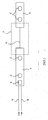
- a first embodiment of a portion of the invention is shown in Fig. 1.
- the invention provides an object proximity sensing system for a vehicle which, in this embodiment, is shown in the form of a reversing aid.
- sensor means comprising at least one proximity sensor 2 may be provided for fitment to a vehicle.
- a plurality of proximity sensors are likely to be provided.
- Proximity sensors suitable for reversing systems are available in the market as commercial items and the specific form of the sensors may vary according to the particular selection of sensor utilized.
- such sensors may comprise a transmitter for emitting a signal such as an ultrasonic signal and a receiver for receiving a reflected signal from an object in the path of the transmitted signal from which the proximity of the object to the sensor can be detected.
- a signal such as an ultrasonic signal
- a receiver for receiving a reflected signal from an object in the path of the transmitted signal from which the proximity of the object to the sensor can be detected.
- each sensor may detect a reflected signal from the same or a different sensor and the signals received by the sensors used to determine the proximity of the object to the sensors.
- Such sensors are known and may comprise a transducer. This part of the system is conventional and the invention is not concerned with the construction and operation of the sensors.
- the present invention mounts at least one sensor, or in this case as shown in Fig. 1, two sensors within a housing unit 3.
- the housing unit 3 is intended to protect the sensors as well as providing an ease of fitment of the sensors to the exterior of a vehicle.
- a transmitter unit 4 is also provided and, as shown in this preferred embodiment, the transmitter unit 4 is contained within the housing unit 3 together with at least one of the sensors 2. In this embodiment the transmitter unit 4 is combined with an electronic control unit within the housing unit 3. Alternatively, the electronic control unit may be provided separate from the transmitter unit 4.
- the sensor(s) 2 are connected to the electronic control unit which receives signals from the sensor(s) 2 when activated and processes the signals for transmission by the transmitter unit 4.
- the transmitter unit 4 may transmit wireless signals on any preferred frequency to be received by a receiving unit 21 as shown in Fig. 4.
- a power source can be provided within the housing unit 3 as a self-contained power source or, more preferably, external connections in the form of at least one wire or preferably positive and negative wires 8 and 9 may extend from the housing unit 3.
- the wires 8 and 9 may be provided with a suitable socket for fitment to a power source on the vehicle or wired into the vehicle. Numerous sources for battery power from a vehicle are provided around the vehicle and may provide suitable points of attachment. For example, the wires 8 and 9 may be connected to the wiring loom for the reversing light(s). In this way a power source for the electronic control unit may be provided such that the sensors and transmitter unit 4 are activated when reverse gear is selected.
- the housing unit 3 containing the sensors 2 is connected by a wire 6 to a second similar housing unit 5 containing at least one and in this case two sensors 2.
- the wire 6 provides communication from the sensors 2 in the housing unit 5 to the electronic control unit in the housing unit 3. It should be noted that this is a preferred embodiment where a single electronic control unit and transmitter unit 4 is used to receive signals from all the sensors.
- a second electronic control unit and transmitter unit could be provided in the housing unit 5 and its own power source may be provided so as to make the units 3 , 5 independent rather than interconnected as shown.
- housing units 3, 5 may be used on some recreational vehicles which may not provide a continuous rear surface on which a single uninterrupted housing unit may be fitted.
- a step may be provided in the middle of the rear of the vehicle and, therefore, it may be better to provide the sensors in two housing units as shown for mounting either side of the step.
- An optional joining piece 7 may be provided to contain a number plate or any other desired artwork such as a manufacturer's logo.
- the housing unit 3 may be fitted directly to the rear of a vehicle so as to provide sensors to an existing vehicle without such apparatus.
- the housing unit 3 could be fitted to a towed vehicle such as a caravan, trailer or a trailer unit of a truck.
- the housing units may be fitted to a vehicle and subsequently released.
- the particular fitment mechanism is not shown in Fig. 1 and any suitable mechanism may be employed as will be apparent to those skilled in the art.
- releasable fitment with any suitable mechanism such as double-sided tape, clamps, bolts or similar can be provided.
- the housing units may be attached to any appropriate part of the vehicle but are typically arranged to be mounted on the bumper.
- FIG. 2 A further embodiment of the invention is shown in Fig. 2.
- a longer continuous housing unit 3 is provided made from a front portion 11 having a front plate 14 and a rear portion 12.
- the sensors 2 are fitted on or in the front plate 14 and the transmitter unit may be housed behind the front plate 14 to be enclosed by the rear portion 12 providing an enclosed housing unit. It will be appreciated that, when fitted to a vehicle, weather conditions may be adverse and the housing unit 3 formed by the adjoined pieces 11 and 12 is preferably substantially waterproof, at least against normal weather.
- Fixing means to adjoin the front portion 11 and rear portion 12 are shown as portions 15 and 16 in which a cooperating fixing member such as a bolt, screw or similar may join the two portions.
- Fig. 2 The apparatus of Fig. 2 is shown in cross-section in Fig. 3, again in exploded fashion whereby the rear portion 12 is shown apart from the front portion 11. In use, the rear portion 12 is fitted into the rear side of the front portion 11 to complete the housing unit.
- FIG. 3 also shows the fitment of the transmitter unit 4 which may also include an electronic control unit as described previously to nest inside the enclosed overall housing unit 3.
- a receiving unit 21 for operation within the cabin of a vehicle is shown.
- This particular receiving unit 21 is shown as a portable unit fitable within the cabin and may include a connection 22 for fitment of the unit into a cigarette lighter socket within a vehicle. This provides a convenient power source for operation of the receiver unit 21 although alternative power sources can be provided.
- An indicating means 23 is provided with the receiver unit 21 to provide the driver with an indication of the proximity of an object to the sensors.
- the indicating means may be a visual display and/or an audible display. This particular embodiment utilizes an audible display such that, as objects get closer to the proximity sensors, the frequency of sounds emitted by the audible indicator increases.
- the receiver unit 21 is preferably provided with a control mechanism 24 that may include a switch.
- the switch is intended to allow alteration of the configuration of the receiver unit 21.
- a receiver unit 21 When a receiver unit 21 is used with a normal vehicle, many such vehicles may be provided with their own proximity sensor units that may be wired through the vehicle body and to the receiver unit 21. Alternatively, they may provide some wireless transmission to the receiver unit 21.
- a sensor unit may be fitted to the trailer and a switch operated such that the receiver unit 21 will now only indicate objects behind the trailer and either disconnect the signals from proximity sensors attached to the rear of the primary vehicle or, alternatively, disconnect the indication means from those primary sensors and instead only operatively connect the indication means to the sensors now on the towed vehicle.
- the invention provides an improved arrangement detecting objects in the path of a vehicle while reversing.
- At least one proximity sensor may be provided in a housing for detachable mounting on the front of a vehicle to provide a warning of objects in the path of the vehicle, for example when manoeuvering in a restricted space such as when parking in a gap between two vehicles.
- Sensor units at the front and rear of the vehicle may communicate wirelessly with the receiver unit within the cabin of the vehicle to provide a visual and/or audible warning of the presence of objects.
- sensors may be configured to generate audible warnings having different characteristics, e.g. pitch, frequency, such that the driver can distinguish between signals generated by proximity to objects at the front and rear of the vehicle.
- sensors at the rear of the vehicle may be activated when the driver selects reverse gear and de-activated when reverse gear is de-selected and sensors at the front of the vehicle may be operated via a manually operable switch within the vehicle, for example on the dashboard.
- the switch may operate a timer circuit so that the front sensors are activated for a pre-determined period of time when I required.
- the timer circuit may be adjustable to allow the length of time the sensors are activated to be set according to the drivers needs and/or complexity of the manoeuvre being undertaken. In this way, the sensors at the front and rear of the vehicle can be operated independently of each other when required. For example, when reversing into a space the front sensors may be turned off and, when driving into a space the front sensors may be turned on (the rear sensors being turned off when reverse gear is not selected).
- sensors at the front and rear of the vehicle may both be operated via a switch within the vehicle.
- the switch may operate a timer circuit and the timer circuit may again be adjustable to set the period of time the sensors are activated.
- a common switch may operate both the front and rear sensors.
- separate switches may be employed to allow the sensors to be operated independently of each other if required.
- a data link input may be provided to allow communication between several transmitter and electronic control units at different positions on the vehicle.
- the rear sensors may be activated when reverse gear is selected as already described and the transmitter unit associated with the rear sensors may transmit a signal to the transmitter unit associated with the front sensors to activate the front sensors.
- the front sensors may operate on a timer circuit.
- the transmitter unit associated with the rear sensors may transmit a signal to de-activate the front sensors when reverse gear is de-selected.
- the system may also be arranged to apply the brakes automatically to slow/stop the vehicle.
- an adjustable timed output may be provided from the transmitter and electronic control unit to allow connection to a control valve for applying the brakes.
Landscapes
- Engineering & Computer Science (AREA)
- Mechanical Engineering (AREA)
- Radar, Positioning & Navigation (AREA)
- Remote Sensing (AREA)
- Transportation (AREA)
- Human Computer Interaction (AREA)
- Measurement Of Length, Angles, Or The Like Using Electric Or Magnetic Means (AREA)
- Control Of Driving Devices And Active Controlling Of Vehicle (AREA)
Applications Claiming Priority (4)
| Application Number | Priority Date | Filing Date | Title |
|---|---|---|---|
| US791824 | 2004-03-04 | ||
| GB0404887A GB0404887D0 (en) | 2004-03-04 | 2004-03-04 | Electronic reversing aid with wireless transmitter and receiver |
| US10/791,824 US7046127B2 (en) | 2000-05-09 | 2004-03-04 | Electronic reversing aid with wireless transmitter and receiver |
| GB0404887 | 2004-03-04 |
Publications (2)
| Publication Number | Publication Date |
|---|---|
| EP1571040A2 true EP1571040A2 (de) | 2005-09-07 |
| EP1571040A3 EP1571040A3 (de) | 2006-07-26 |
Family
ID=34751842
Family Applications (1)
| Application Number | Title | Priority Date | Filing Date |
|---|---|---|---|
| EP05250990A Withdrawn EP1571040A3 (de) | 2004-03-04 | 2005-02-22 | Annäherungsdetektion-System für ein Fahrzeug |
Country Status (1)
| Country | Link |
|---|---|
| EP (1) | EP1571040A3 (de) |
Cited By (6)
| Publication number | Priority date | Publication date | Assignee | Title |
|---|---|---|---|---|
| EP1826107A3 (de) * | 2006-02-28 | 2008-03-26 | James Richard Yates | System zum Manövrieren von Anhängern |
| US7598845B2 (en) * | 2005-11-09 | 2009-10-06 | Chrysler Group Llc | Towing load detection system |
| DE102008047282A1 (de) * | 2008-09-16 | 2010-04-01 | Hamm, Wolfgang A. | Tagfahrleuchte |
| GB2483877A (en) * | 2010-09-22 | 2012-03-28 | Jonathan Keith Ross | Parking assist system |
| GB2561531A (en) * | 2017-01-24 | 2018-10-24 | Arthur Elliott John | A lighting board |
| EP3254897B1 (de) * | 2016-05-27 | 2024-03-27 | Ben Snell | Signalisierungssystem |
Citations (1)
| Publication number | Priority date | Publication date | Assignee | Title |
|---|---|---|---|---|
| US6604592B2 (en) * | 1998-07-11 | 2003-08-12 | Wabco Gmbh | Method and device for assisting a driver during reverse travel |
Family Cites Families (9)
| Publication number | Priority date | Publication date | Assignee | Title |
|---|---|---|---|---|
| GB2220512A (en) * | 1988-07-07 | 1990-01-10 | Michael Hsu | Parking sensor |
| JPH08192700A (ja) * | 1995-01-18 | 1996-07-30 | Bridgestone Corp | 車両障害物センサ |
| US6268803B1 (en) * | 1998-08-06 | 2001-07-31 | Altra Technologies Incorporated | System and method of avoiding collisions |
| US6696931B2 (en) * | 1998-09-23 | 2004-02-24 | Directed Electronics, Inc. | Retrofittable vehicle collision warning apparatus |
| GB2344481B (en) * | 1998-12-05 | 2001-02-21 | Terence Boddy | Auto park |
| DE10035124B4 (de) * | 2000-07-19 | 2016-03-31 | Volkswagen Ag | Elektronische Abstandswarnanlage |
| US6879248B2 (en) * | 2001-05-31 | 2005-04-12 | Omega Patents, L.L.C. | Back-up warning system for a vehicle and related method |
| DE20110339U1 (de) * | 2001-06-22 | 2002-10-24 | MEKRA Lang GmbH & Co. KG, 90765 Fürth | Parkhilfe zur Verwendung in einem Kraftfahrzeug |
| US20030111902A1 (en) * | 2001-12-17 | 2003-06-19 | David Thiede | Intelligent braking system and method |
-
2005
- 2005-02-22 EP EP05250990A patent/EP1571040A3/de not_active Withdrawn
Patent Citations (1)
| Publication number | Priority date | Publication date | Assignee | Title |
|---|---|---|---|---|
| US6604592B2 (en) * | 1998-07-11 | 2003-08-12 | Wabco Gmbh | Method and device for assisting a driver during reverse travel |
Cited By (7)
| Publication number | Priority date | Publication date | Assignee | Title |
|---|---|---|---|---|
| US7598845B2 (en) * | 2005-11-09 | 2009-10-06 | Chrysler Group Llc | Towing load detection system |
| EP1826107A3 (de) * | 2006-02-28 | 2008-03-26 | James Richard Yates | System zum Manövrieren von Anhängern |
| DE102008047282A1 (de) * | 2008-09-16 | 2010-04-01 | Hamm, Wolfgang A. | Tagfahrleuchte |
| GB2483877A (en) * | 2010-09-22 | 2012-03-28 | Jonathan Keith Ross | Parking assist system |
| EP3254897B1 (de) * | 2016-05-27 | 2024-03-27 | Ben Snell | Signalisierungssystem |
| GB2561531A (en) * | 2017-01-24 | 2018-10-24 | Arthur Elliott John | A lighting board |
| GB2561531B (en) * | 2017-01-24 | 2019-03-13 | Arthur Elliott John | A lighting board |
Also Published As
| Publication number | Publication date |
|---|---|
| EP1571040A3 (de) | 2006-07-26 |
Similar Documents
| Publication | Publication Date | Title |
|---|---|---|
| US7046127B2 (en) | Electronic reversing aid with wireless transmitter and receiver | |
| US7061402B1 (en) | Emergency vehicle warning system | |
| US6879248B2 (en) | Back-up warning system for a vehicle and related method | |
| US6720868B2 (en) | Back-up warning system in a license plate holder and related method | |
| US7341264B2 (en) | Trailer hitch mounted reverse sensing system | |
| US5666103A (en) | Wireless safety indicator control system for towed vehicles | |
| USRE40878E1 (en) | Trailer hitch mount for vehicle backup sensor | |
| GB2344481A (en) | Electric reversing aid | |
| US20170080852A1 (en) | A rear light system for a towable vehicle | |
| AU2006300963B2 (en) | Object detection system | |
| US7224264B2 (en) | Radar hitch | |
| US5914652A (en) | Object sensing device for a vehicle | |
| US7986259B2 (en) | Motorcycle radar detection system | |
| US11135883B2 (en) | Vehicular sensing system with ultrasonic sensor at trailer hitch | |
| US7225070B2 (en) | Parking guidance system for large vehicles | |
| CN111497750A (zh) | 一体化警示装置及外后视镜组件 | |
| WO2008004166A1 (en) | Vehicle light unit | |
| US20230365069A1 (en) | Universal blind spot detection system | |
| GB2375901A (en) | Wireless remote controlled vehicle lighting Board | |
| US6967568B2 (en) | Rear turning signal sensor | |
| EP1153804A1 (de) | Elektronische Rückwärtsfahrhilfe mit drahtlosem Sender und Empfänger | |
| JPH0143661Y2 (de) | ||
| JP2005297651A (ja) | 車両用障害物検出装置 | |
| EP1997687A2 (de) | Vorrichtung zum Helfen beim Manövrieren und Einparken von gewerblichen und industriellen Kraftfahrzeugen | |
| Katayama et al. | A short range detecting system by ultrasonic sensor |
Legal Events
| Date | Code | Title | Description |
|---|---|---|---|
| PUAI | Public reference made under article 153(3) epc to a published international application that has entered the european phase |
Free format text: ORIGINAL CODE: 0009012 |
|
| AK | Designated contracting states |
Kind code of ref document: A2 Designated state(s): AT BE BG CH CY CZ DE DK EE ES FI FR GB GR HU IE IS IT LI LT LU MC NL PL PT RO SE SI SK TR |
|
| AX | Request for extension of the european patent |
Extension state: AL BA HR LV MK YU |
|
| PUAL | Search report despatched |
Free format text: ORIGINAL CODE: 0009013 |
|
| AK | Designated contracting states |
Kind code of ref document: A3 Designated state(s): AT BE BG CH CY CZ DE DK EE ES FI FR GB GR HU IE IS IT LI LT LU MC NL PL PT RO SE SI SK TR |
|
| AX | Request for extension of the european patent |
Extension state: AL BA HR LV MK YU |
|
| AKX | Designation fees paid | ||
| REG | Reference to a national code |
Ref country code: DE Ref legal event code: 8566 |
|
| 17P | Request for examination filed |
Effective date: 20070404 |
|
| RBV | Designated contracting states (corrected) |
Designated state(s): AT BE BG CH CY CZ DE DK EE ES FI FR GB GR HU IE IS IT LI LT LU MC NL PL PT RO SE SI SK TR |
|
| 17Q | First examination report despatched |
Effective date: 20071102 |
|
| STAA | Information on the status of an ep patent application or granted ep patent |
Free format text: STATUS: THE APPLICATION IS DEEMED TO BE WITHDRAWN |
|
| 18D | Application deemed to be withdrawn |
Effective date: 20110729 |