EP3254897B1 - Signalisierungssystem - Google Patents
Signalisierungssystem Download PDFInfo
- Publication number
- EP3254897B1 EP3254897B1 EP17000903.9A EP17000903A EP3254897B1 EP 3254897 B1 EP3254897 B1 EP 3254897B1 EP 17000903 A EP17000903 A EP 17000903A EP 3254897 B1 EP3254897 B1 EP 3254897B1
- Authority
- EP
- European Patent Office
- Prior art keywords
- light
- signalling
- vehicle
- sensors
- signal
- Prior art date
- Legal status (The legal status is an assumption and is not a legal conclusion. Google has not performed a legal analysis and makes no representation as to the accuracy of the status listed.)
- Active
Links
Images



Classifications
-
- B—PERFORMING OPERATIONS; TRANSPORTING
- B60—VEHICLES IN GENERAL
- B60Q—ARRANGEMENT OF SIGNALLING OR LIGHTING DEVICES, THE MOUNTING OR SUPPORTING THEREOF OR CIRCUITS THEREFOR, FOR VEHICLES IN GENERAL
- B60Q1/00—Arrangement of optical signalling or lighting devices, the mounting or supporting thereof or circuits therefor
- B60Q1/26—Arrangement of optical signalling or lighting devices, the mounting or supporting thereof or circuits therefor the devices being primarily intended to indicate the vehicle, or parts thereof, or to give signals, to other traffic
- B60Q1/30—Arrangement of optical signalling or lighting devices, the mounting or supporting thereof or circuits therefor the devices being primarily intended to indicate the vehicle, or parts thereof, or to give signals, to other traffic for indicating rear of vehicle, e.g. by means of reflecting surfaces
- B60Q1/305—Indicating devices for towed vehicles
-
- B—PERFORMING OPERATIONS; TRANSPORTING
- B60—VEHICLES IN GENERAL
- B60Q—ARRANGEMENT OF SIGNALLING OR LIGHTING DEVICES, THE MOUNTING OR SUPPORTING THEREOF OR CIRCUITS THEREFOR, FOR VEHICLES IN GENERAL
- B60Q1/00—Arrangement of optical signalling or lighting devices, the mounting or supporting thereof or circuits therefor
- B60Q1/26—Arrangement of optical signalling or lighting devices, the mounting or supporting thereof or circuits therefor the devices being primarily intended to indicate the vehicle, or parts thereof, or to give signals, to other traffic
- B60Q1/30—Arrangement of optical signalling or lighting devices, the mounting or supporting thereof or circuits therefor the devices being primarily intended to indicate the vehicle, or parts thereof, or to give signals, to other traffic for indicating rear of vehicle, e.g. by means of reflecting surfaces
-
- B—PERFORMING OPERATIONS; TRANSPORTING
- B60—VEHICLES IN GENERAL
- B60P—VEHICLES ADAPTED FOR LOAD TRANSPORTATION OR TO TRANSPORT, TO CARRY, OR TO COMPRISE SPECIAL LOADS OR OBJECTS
- B60P3/00—Vehicles adapted to transport, to carry or to comprise special loads or objects
- B60P3/12—Vehicles adapted to transport, to carry or to comprise special loads or objects for salvaging damaged vehicles
- B60P3/125—Vehicles adapted to transport, to carry or to comprise special loads or objects for salvaging damaged vehicles by supporting only part of the vehicle, e.g. front- or rear-axle
- B60P3/127—Vehicles adapted to transport, to carry or to comprise special loads or objects for salvaging damaged vehicles by supporting only part of the vehicle, e.g. front- or rear-axle on a tow dolly
-
- B—PERFORMING OPERATIONS; TRANSPORTING
- B60—VEHICLES IN GENERAL
- B60Q—ARRANGEMENT OF SIGNALLING OR LIGHTING DEVICES, THE MOUNTING OR SUPPORTING THEREOF OR CIRCUITS THEREFOR, FOR VEHICLES IN GENERAL
- B60Q1/00—Arrangement of optical signalling or lighting devices, the mounting or supporting thereof or circuits therefor
- B60Q1/26—Arrangement of optical signalling or lighting devices, the mounting or supporting thereof or circuits therefor the devices being primarily intended to indicate the vehicle, or parts thereof, or to give signals, to other traffic
-
- B—PERFORMING OPERATIONS; TRANSPORTING
- B60—VEHICLES IN GENERAL
- B60Q—ARRANGEMENT OF SIGNALLING OR LIGHTING DEVICES, THE MOUNTING OR SUPPORTING THEREOF OR CIRCUITS THEREFOR, FOR VEHICLES IN GENERAL
- B60Q1/00—Arrangement of optical signalling or lighting devices, the mounting or supporting thereof or circuits therefor
- B60Q1/26—Arrangement of optical signalling or lighting devices, the mounting or supporting thereof or circuits therefor the devices being primarily intended to indicate the vehicle, or parts thereof, or to give signals, to other traffic
- B60Q1/30—Arrangement of optical signalling or lighting devices, the mounting or supporting thereof or circuits therefor the devices being primarily intended to indicate the vehicle, or parts thereof, or to give signals, to other traffic for indicating rear of vehicle, e.g. by means of reflecting surfaces
- B60Q1/301—Arrangement of optical signalling or lighting devices, the mounting or supporting thereof or circuits therefor the devices being primarily intended to indicate the vehicle, or parts thereof, or to give signals, to other traffic for indicating rear of vehicle, e.g. by means of reflecting surfaces by means of surfaces, e.g. metal plate, reflecting the light of an external light source
- B60Q1/3015—Arrangement of optical signalling or lighting devices, the mounting or supporting thereof or circuits therefor the devices being primarily intended to indicate the vehicle, or parts thereof, or to give signals, to other traffic for indicating rear of vehicle, e.g. by means of reflecting surfaces by means of surfaces, e.g. metal plate, reflecting the light of an external light source combined with a lamp
-
- B—PERFORMING OPERATIONS; TRANSPORTING
- B60—VEHICLES IN GENERAL
- B60Q—ARRANGEMENT OF SIGNALLING OR LIGHTING DEVICES, THE MOUNTING OR SUPPORTING THEREOF OR CIRCUITS THEREFOR, FOR VEHICLES IN GENERAL
- B60Q1/00—Arrangement of optical signalling or lighting devices, the mounting or supporting thereof or circuits therefor
- B60Q1/26—Arrangement of optical signalling or lighting devices, the mounting or supporting thereof or circuits therefor the devices being primarily intended to indicate the vehicle, or parts thereof, or to give signals, to other traffic
- B60Q1/34—Arrangement of optical signalling or lighting devices, the mounting or supporting thereof or circuits therefor the devices being primarily intended to indicate the vehicle, or parts thereof, or to give signals, to other traffic for indicating change of drive direction
-
- B—PERFORMING OPERATIONS; TRANSPORTING
- B60—VEHICLES IN GENERAL
- B60Q—ARRANGEMENT OF SIGNALLING OR LIGHTING DEVICES, THE MOUNTING OR SUPPORTING THEREOF OR CIRCUITS THEREFOR, FOR VEHICLES IN GENERAL
- B60Q9/00—Arrangement or adaptation of signal devices not provided for in one of main groups B60Q1/00 - B60Q7/00, e.g. haptic signalling
- B60Q9/002—Arrangement or adaptation of signal devices not provided for in one of main groups B60Q1/00 - B60Q7/00, e.g. haptic signalling for parking purposes, e.g. for warning the driver that his vehicle has contacted or is about to contact an obstacle
- B60Q9/004—Arrangement or adaptation of signal devices not provided for in one of main groups B60Q1/00 - B60Q7/00, e.g. haptic signalling for parking purposes, e.g. for warning the driver that his vehicle has contacted or is about to contact an obstacle using wave sensors
-
- B—PERFORMING OPERATIONS; TRANSPORTING
- B60—VEHICLES IN GENERAL
- B60Q—ARRANGEMENT OF SIGNALLING OR LIGHTING DEVICES, THE MOUNTING OR SUPPORTING THEREOF OR CIRCUITS THEREFOR, FOR VEHICLES IN GENERAL
- B60Q9/00—Arrangement or adaptation of signal devices not provided for in one of main groups B60Q1/00 - B60Q7/00, e.g. haptic signalling
- B60Q9/008—Arrangement or adaptation of signal devices not provided for in one of main groups B60Q1/00 - B60Q7/00, e.g. haptic signalling for anti-collision purposes
-
- B—PERFORMING OPERATIONS; TRANSPORTING
- B60—VEHICLES IN GENERAL
- B60R—VEHICLES, VEHICLE FITTINGS, OR VEHICLE PARTS, NOT OTHERWISE PROVIDED FOR
- B60R1/00—Optical viewing arrangements; Real-time viewing arrangements for drivers or passengers using optical image capturing systems, e.g. cameras or video systems specially adapted for use in or on vehicles
- B60R1/02—Rear-view mirror arrangements
- B60R1/08—Rear-view mirror arrangements involving special optical features, e.g. avoiding blind spots, e.g. convex mirrors; Side-by-side associations of rear-view and other mirrors
-
- F—MECHANICAL ENGINEERING; LIGHTING; HEATING; WEAPONS; BLASTING
- F21—LIGHTING
- F21S—NON-PORTABLE LIGHTING DEVICES; SYSTEMS THEREOF; VEHICLE LIGHTING DEVICES SPECIALLY ADAPTED FOR VEHICLE EXTERIORS
- F21S43/00—Signalling devices specially adapted for vehicle exteriors, e.g. brake lamps, direction indicator lights or reversing lights
-
- F—MECHANICAL ENGINEERING; LIGHTING; HEATING; WEAPONS; BLASTING
- F21—LIGHTING
- F21S—NON-PORTABLE LIGHTING DEVICES; SYSTEMS THEREOF; VEHICLE LIGHTING DEVICES SPECIALLY ADAPTED FOR VEHICLE EXTERIORS
- F21S43/00—Signalling devices specially adapted for vehicle exteriors, e.g. brake lamps, direction indicator lights or reversing lights
- F21S43/10—Signalling devices specially adapted for vehicle exteriors, e.g. brake lamps, direction indicator lights or reversing lights characterised by the light source
-
- G—PHYSICS
- G01—MEASURING; TESTING
- G01S—RADIO DIRECTION-FINDING; RADIO NAVIGATION; DETERMINING DISTANCE OR VELOCITY BY USE OF RADIO WAVES; LOCATING OR PRESENCE-DETECTING BY USE OF THE REFLECTION OR RERADIATION OF RADIO WAVES; ANALOGOUS ARRANGEMENTS USING OTHER WAVES
- G01S13/00—Systems using the reflection or reradiation of radio waves, e.g. radar systems; Analogous systems using reflection or reradiation of waves whose nature or wavelength is irrelevant or unspecified
- G01S13/88—Radar or analogous systems specially adapted for specific applications
- G01S13/93—Radar or analogous systems specially adapted for specific applications for anti-collision purposes
- G01S13/931—Radar or analogous systems specially adapted for specific applications for anti-collision purposes of land vehicles
-
- G—PHYSICS
- G01—MEASURING; TESTING
- G01S—RADIO DIRECTION-FINDING; RADIO NAVIGATION; DETERMINING DISTANCE OR VELOCITY BY USE OF RADIO WAVES; LOCATING OR PRESENCE-DETECTING BY USE OF THE REFLECTION OR RERADIATION OF RADIO WAVES; ANALOGOUS ARRANGEMENTS USING OTHER WAVES
- G01S17/00—Systems using the reflection or reradiation of electromagnetic waves other than radio waves, e.g. lidar systems
- G01S17/88—Lidar systems specially adapted for specific applications
- G01S17/93—Lidar systems specially adapted for specific applications for anti-collision purposes
- G01S17/931—Lidar systems specially adapted for specific applications for anti-collision purposes of land vehicles
-
- G—PHYSICS
- G08—SIGNALLING
- G08G—TRAFFIC CONTROL SYSTEMS
- G08G1/00—Traffic control systems for road vehicles
- G08G1/16—Anti-collision systems
- G08G1/165—Anti-collision systems for passive traffic, e.g. including static obstacles, trees
-
- B—PERFORMING OPERATIONS; TRANSPORTING
- B60—VEHICLES IN GENERAL
- B60Q—ARRANGEMENT OF SIGNALLING OR LIGHTING DEVICES, THE MOUNTING OR SUPPORTING THEREOF OR CIRCUITS THEREFOR, FOR VEHICLES IN GENERAL
- B60Q2900/00—Features of lamps not covered by other groups in B60Q
- B60Q2900/10—Retrofit arrangements
-
- B—PERFORMING OPERATIONS; TRANSPORTING
- B60—VEHICLES IN GENERAL
- B60Q—ARRANGEMENT OF SIGNALLING OR LIGHTING DEVICES, THE MOUNTING OR SUPPORTING THEREOF OR CIRCUITS THEREFOR, FOR VEHICLES IN GENERAL
- B60Q2900/00—Features of lamps not covered by other groups in B60Q
- B60Q2900/30—Lamps commanded by wireless transmissions
Definitions
- This invention relates to a signalling system for vehicles.
- Trailer boards are available for mounting to the rear of vehicle trailers or caravans, which trailer boards comprise an elongate board carrying at least a basic set of signalling lights such as tail lights and indicators.
- the trailer board has a cable terminating with a special plug adapted to detachably connect to an electrical socket on the car, e.g. a 12N plug and socket system. This physical connection takes power from the car battery, and multiple signals from the car's signalling system.
- the socket on the car needs to be fitted and wired to its electrical and signalling system by a trained installer, and is typically associated with fitting a tow bar attachment or similar. When connected, the trailer board replicates signalling from the car to the signalling lights to ensure that following vehicles can see them.
- a first aspect of the invention provides a signalling system for vehicles, comprising: one or more optical sensors for removable attachment to a respective vehicle light, which sensors are configured to generate a signal responsive to detecting emitted light from the vehicle light to which it is attached, the system being arranged responsive to receiving a signal from the one or more optical sensors to output a signal to an external signalling unit to cause a corresponding light on said external signalling unit to operate.
- Plural optical sensors are provided, each connected to a control unit by means of respective lengthwise conductors, the control unit comprising circuitry for relaying the sensor signals to corresponding lights of an external signalling unit.
- the system further comprises a trailer board for removable mounting to the rear of a vehicle, the trailer board carrying on a rear surface a plurality of signalling lights, and wherein the control unit is configured to relay sensor signals received from the sensors to a corresponding signalling light on the trailer board.
- Each optical sensor comprises a light detector surrounded by a wall having an end surface adapted for removable attachment to a vehicle light.
- the surrounding wall is formed of a deformable material with a substantially planar end surface which, in use, is removably attached to a vehicle light by suction.
- the system may comprise a conductor for receiving electrical power from a vehicle, the conductor being terminated by a plug adapted to connect to an existing power outlet of a vehicle, e.g. a cigarette lighter outlet.
- the system may comprise an external connector plug or socket adapted to connect to an existing socket or plug of a vehicular trailer board.
- the system further comprises one or more proximity parking sensors adapted for retrofitting to a vehicular trailer board, and means for relaying signals produced by the parking sensors to an audible or visual unit which may be carried within the vehicle.
- the proximity sensor(s) for example, may be ultrasonic or infrared.
- FIG. 1 there is shown a potential situation in which embodiments of the invention provide advantageous use.
- This common arrangement obscures at least some or all of the rear signalling lights 7 contrary to good safety practise and legislation.
- Figure 2 shows a first embodiment vehicular signalling system for overcoming or alleviating the abovementioned disadvantages, in particular without the need for specialised fitting of an electrical connector to the vehicle exterior. It comprises a signalling control unit 9 which is mounted to the vehicle 1, for example to the rear bumper/fender, to the bracket 5 or even to a trailer board 10, and a plurality of optical light sensors 11 in signal communication with the control unit, and which in use are detachably mountable to respective ones of the rear signalling lights.
- a signalling control unit 9 which is mounted to the vehicle 1, for example to the rear bumper/fender, to the bracket 5 or even to a trailer board 10, and a plurality of optical light sensors 11 in signal communication with the control unit, and which in use are detachably mountable to respective ones of the rear signalling lights.
- the control unit 9 is in signal communication with the trailer board 10 and is configured in use to relay signals sensed by the light sensors 11 to an electrical system of the trailer board 10 so as to mimic in real-time, or near real-time, signalling from the vehicle 1.
- signalling refers to visible output from any or all of the rear tail lights, indicator (turn) lights, fog light(s), and possibly a reversing light.
- the trailer board 10 is shown and comprises an elongate mounting board 20 carrying on its rear surface a plurality of electrical lights, comprising in this example of:
- a mounting area 30 is provided for a registration tail plate, if needed, and optionally one or more mounts 32 are provided for reverse parking sensors, if needed.
- Electrical conductors shown in dotted lines, connect each of the above lights 22 - 27 to a connector plug 35.
- the conductors can pass between laminated sheets that form the trailer board 10 and/or may be wires or conductive tracks printed on substrate.
- the plug 35 can be a conventional plug, e.g. a 12N connector currently used for trailer boards in the UK and certain parts of Europe. Other types of connector can also be employed.
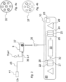
- Figure 4a shows the seven-terminal layout of the plug 35, with terminals 1, 3, 4, 6 being spring pins and terminals 2, 5, 7 being tubes.
- the control unit 9 comprises circuitry mounted on one or more printed circuit boards and housed within a waterproof casing.
- a socket 37 is provided on the exterior of the waterproof casing for receiving the plug 35; the socket 37 may be covered by a removable waterproof cap for when not in use.
- Figure 4b shows the layout of the socket 37, again a 12N socket, which has the opposite male/female orientation of terminals than that shown in Figure 4a , with terminals 1, 3, 4, 6 being tubes and terminals 2, 5, 7 being spring pins.
- the 12N connector is detailed further in the ISO1724 standard.
- the wiring of the pins correspond to the following signal functions: Pin No. Colour Function 1 Yellow Left Indicator 2 Blue Fog Light 3 White Earth 4 Green Right Indicator 5 Brown Right Tail / Side Light 6 Red Brake / Stop Lights 7 Black Left Tail / Side Light
- the control unit 9 Connected to the control unit 9 are, in this embodiment, six external optical sensors 11a-f by respective conductors 39a-f. These conductors 39a-f are covered by an insulating sleeve and are of sufficient length to extend to the peripheral edges of the vehicle (where most lights are located) from the centre. Different conductors may have different lengths. Also connected to the control unit 9 is an external 12v plug 41 via lead 43. The 12v plug 41 may be shaped and dimensioned to locate within the provided cigarette lighter receptacle of the vehicle 1, enabling the control unit 9 to be powered by passing the plug and lead 43 through the boot/trunk of the vehicle or some other exterior aperture.
- FIG. 5 shows how the control unit 9 can be directly mounted on the rear of the trailer board 10, or integrated into the trailer board when sold.
- the conductors 39a-f are connected to the control unit 9 by a single plug 47 which locates within a corresponding socket 48 on the control unit.
- Each of the optical sensors 11a-f is configured to removably attach to the external surface of the vehicle light cluster, which typically comprises a smooth, transparent plastic cover beneath which bulbs are located.
- Figures 6a and 6b show different types of optical sensor, either of which is suitable. Other types are possible.
- FIG. 6a which shows only one sensor 11a, it comprises a base member 51, which may be a covered circuit board, onto which is mounted a photodetector 53 or similar component.
- the photodetector 53 generates a signal responsive to emitted light above a certain intensity which it transmits to the conductor 39a.
- a perimeter wall 55 surrounds the photodetector 53 for the purpose of preventing or mitigating other light sources from affecting the operation of the photodetector, and/or debris such as mud from the road affecting performance.
- the perimeter wall 55 is provided in the form of a suction cup made of relatively flexible and deformable material such as rubber which enables straightforward removable attachment of its flat, end surface 57 to the cover of a selected vehicle lamp.
- the senor 11a comprises a deformable or non-deformable perimeter wall 59 which likewise surrounds the photodetector 53 and which attaches to the vehicle lamp using one or more adhesive stickers 61, such as provided by 3M (typically referred to as "dual lock coins").
- adhesive stickers 61 such as provided by 3M (typically referred to as "dual lock coins").
- Other forms of adhesion or attachment can be employed, e.g. using a hook and loop system.
- each of the sensors 11a-f will be labelled for user-attachment to a corresponding one of the rear lights, e.g. using a number or colour code.
- the table below shows an example. Placement of the sensor over the appropriate rear light is for the user to manage.
- the circuitry within the control system 9 is arranged such as to detect the one or more signals produced by the sensors 11a-f and to relay these to the corresponding signal lamp provided on the trailer board 10 as shown in Figures 8a and 8b which are rear and partial side views respectively.
- the term 'relay' in this sense means to receive and pass on.
- processing is involved, for example by means of detecting the signal strength from the sensors 11a-f and only issuing a signal to the corresponding lamp of the trailer board 10 if the signal strength is above a predetermined threshold. This helps avoid, for example, ambient light at one of the sensors 11a-f causing a lamp to erroneously turn on.
- signal strength refers to the brightness or intensity of the sensed light, which could be represented in analogue or digital form.
- control system 9 may be provided in hardware, software or a combination of both.
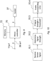
- Figure 9 shows one example in which the control system 9 comprises a micro-controller 70 and a memory 72.
- the controller 70 can be one or more processors, one or more microcontrollers or a combination of the two.
- the presence of the micro-controller 70 ensures that "false triggers" caused by light pollution from other sources can be effectively filtered out.
- the memory 72 can be a separate hardware module or provided 'on-board' the controller 70.
- the memory 72 can be implemented in any form.
- the memory 72 can store a program which, when executed by the controller 70, performs certain functions of the control system 9.
- Figure 10 shows in overview the steps performed by a program stored on the memory 72 when executed on the controller 70.
- a signal is received from one or more of the sensors 11a-f.
- step 10.2 the signal strength from the, or each, signal is measured.
- step 10.3 for each received signal it is determined if the signal strength is above a predetermined threshold. If so, in step 10.4 the corresponding lamp is enabled by means of issuing a corresponding signal to the appropriate terminal of the socket 37. It will be appreciated that these steps can be implemented in hardware, as opposed to software, or using a combination of both.
- the controller 70 may be a microcontroller programmed to work in tandem with an embedded analog to digital converter (ADC) to process voltage level samples and compare them to a programmed or runtime adjustable threshold voltage; based on these values, and in some cases combinations of values, the microcontroller illuminates the respective lights of the trailer board 10.
- ADC embedded analog to digital converter
- the microcontroller 70 may continually instruct the ADC to sample voltage levels from the respective sensor pins, connected to respective sensors 11a - 11f through printed circuit board connectors and traces.
- the sensors 11a - 11f may provide a voltage level to the respective pins on the microcontroller 70 which is dependent on the light intensity the sensors are receiving.
- the ADC passes the converted digital samples to the microcontroller 70.
- the microcontroller 70 continuously monitors the digital samples and determines whether or not they are above a threshold voltage. If the digital sample is above the threshold value and/or if a multiplicity of these digital samples are above the threshold value at the same time (in the case of braking) then the microcontroller 70 toggles the relevant output pin or pins. When the relevant output pin or pins is toggled, the appropriate light on the trailer board 10 is then illuminated.
- the microcontroller 70 is part of the transmission lights controller board and is one of many components required to make the system work.
- the microcontroller 70 samples the voltage levels from the sensors through the ADC.
- the microcontroller 70 is programmed to compare the voltage levels that are sampled and determine if they are above a threshold or below a threshold. If the voltage levels from the ADC are above a threshold, the microcontroller 70 controls one of its output port pins to go high, causing the respective light on the trailer board 10 to illuminate.
- a communications peripheral may be provided on the microcontroller 70 in order to communicate with external devices (e.g. an ultrasonic portion of the product to be described below, which serves as a distance measurement to aid in reversing and parking; other applications may also arise in the future for coupling to the product.)
- Program and Processing instructions are stored in the microcontroller 70 allowing it to control
- the ability for the microcontroller 70 and ADC to work in tandem to sample signals provides a precise and consistent way of implementing this product.
- the microcontroller 70 is a programmable device and can be programmed with diagnostic and fault tolerant code to increase reliability and detect and correct for issues while in operation.
- any or all of the above-mentioned conductors between the control system 9 and the sensors 11a-f and the trailer board 10 can be replaced with wireless communications devices, e.g. using Bluetooth as a wireless communications protocol.
- a parking sensor facility may be incorporated into the control system 9. More specifically, housed within the casing of the control system 9 will be circuitry, being a parking sensor controller, which draws power from the above-mentioned components connected to the car's power supply. One or more further conductors will extend from the control system 9 to respective ultrasonic parking sensors which can, e.g. locate within respective mounting holes or recesses 32 of the trailer board 10 as indicated in Figure 3 . Additionally, therefore, a retro-fit reverse parking system can be provided to account for the vehicle 1 having no such facility, or in which the vehicle's own sensors are obscured by objects mounted to the rear or by the trailer board itself.
- the audible indication provided by the parking sensor controller can be made via a speaker on the controller, and/or by a separate speaker that can locate within the vehicle itself and which receives signals from the controller by wired or wireless means. Additionally, or alternatively, an application for running on a smartphone or the like can be provided, and arranged to pair and communicate with the parking sensor wirelessly to provide an indication of object proximity.
- control system 9 can be provided as a separate module for use with existing trailer boards available on the market. In other embodiments, the control system 9 can be provided as part of a trailer board assembly, being a stand-alone product for purchase.
- the reverse parking sensors may be provided as a separate module such that they are separate from the other sensors.
- An existing trailerboard socket found on the vehicle is connected to the reverse parking sensor controller to receive a signal from the controller.
Landscapes
- Engineering & Computer Science (AREA)
- Mechanical Engineering (AREA)
- Radar, Positioning & Navigation (AREA)
- Remote Sensing (AREA)
- Physics & Mathematics (AREA)
- General Physics & Mathematics (AREA)
- Transportation (AREA)
- Human Computer Interaction (AREA)
- Electromagnetism (AREA)
- Computer Networks & Wireless Communication (AREA)
- General Engineering & Computer Science (AREA)
- Health & Medical Sciences (AREA)
- Public Health (AREA)
- Multimedia (AREA)
- Lighting Device Outwards From Vehicle And Optical Signal (AREA)
Claims (4)
- Signalisierungssystem für Fahrzeuge, umfassend:einen oder mehrere optische Sensoren (11a-f) zum abnehmbaren Anbringen an einer jeweiligen Fahrzeugleuchte, wobei die optischen Sensoren (1 1a-f) konfiguriert sind, um als Reaktion auf ein Erfassen von emittiertem Licht von der Fahrzeugleuchte, an der sie angebracht sind, ein Signal zu erzeugen, wobei das System angeordnet ist, um als Reaktion auf ein Empfangen eines Signals von dem einen oder den mehreren optischen Sensoren (11a-f) ein Signal an eine externe Signalisierungseinheit (20) auszugeben, um zu bewirken, dass eine entsprechende Leuchte an der externen Signalisierungseinheit (20) betrieben wird;wobei mehrere optische Sensoren (11a-f) bereitgestellt sind, die jeweils mittels entsprechender Längsleiter mit einer Steuereinheit (9) verbunden sind, die Steuereinheit (9) umfassend eine Schaltung zum Weiterleiten der Sensorsignale an entsprechende Leuchten einer externen Signalisierungseinheit (20);eine Anhängertafel (10) zum abnehmbaren Montieren an dem Heck eines Fahrzeugs (1), wobei die Anhängertafel (10) auf einer hinteren Oberfläche eine Vielzahl von Signalisierungsleuchten (20) trägt, und wobei die Steuereinheit (9)konfiguriert ist, um Sensorsignale, die von den Sensoren empfangen werden, an eine entsprechende Signalisierungsleuchte an der Anhängertafel (10) weiterzuleiten;dadurch gekennzeichnet, dass das System einen oder mehrere Näherungssensoren (32) umfasst, die zum Nachrüsten an der Anhängertafel (10) angepasst sind, undEinrichtungen zum Weiterleiten von Signalen, die von den Näherungssensoren (32) erzeugt werden, an eine akustische oder optische Einheit, die in dem Fahrzeug (1) getragen werden kann, und dassjeder optische Sensor (11a-f) einen Lichtdetektor (53) umfasst,der von einer Wand (55) umgeben ist, die eine Stirnfläche aufweist, die zum abnehmbaren Anbringen an einer Fahrzeugleuchte angepasst ist, undwobei die umgebende Wand (55) aus einem verformbaren Material mit einer im Wesentlichen ebenen Stirnfläche gebildet ist, die im Gebrauch durch Ansaugen abnehmbar an einer Fahrzeugleuchte angebracht ist.
- Signalisierungssystem nach einem vorhergehenden Anspruch, wobei das System einen Leiter zum Erhalten elektrischer Energie von einem Fahrzeug umfasst, wobei der Leiter mit einem Stecker abgeschlossen ist, der angepasst ist, um mit einer vorhandenen Steckdose eines Fahrzeugs verbunden zu werden, z. B. mit einer Zigarettenanzünderbuchse.
- Signalisierungssystem nach einem der vorhergehenden Ansprüche, wobei das System angepasst ist, um als Reaktion auf ein Empfangen des Signals von den optischen Sensoren die Stärke oder Intensität des Lichts zu bestimmen, das von jedem der Sensoren erfasst wird, und das Signal nur dann an die externe Signalisierungseinheit auszugeben, wenn die Stärke oder Intensität über einem vorgegebenen Schwellenwert ist.
- Signalisierungssystem nach Anspruch 3, wobei das System einen Mikrocontroller mit einem chipintegrierten Analog-Digital-Wandler umfasst, der konfiguriert ist, um ein Eingangssignal abzutasten, das indikativ für die Stärke oder Intensität von Licht ist, das von den Sensoren erfasst wird,
und um zu bestimmen, ob die digitale Darstellung der abgetasteten Eingangssignale über dem vorbestimmten Schwellenwert ist, die in einem chipintegrierten Speicher gespeichert sind.
Applications Claiming Priority (1)
| Application Number | Priority Date | Filing Date | Title |
|---|---|---|---|
| GB1609390.8A GB2550896B (en) | 2016-05-27 | 2016-05-27 | Signalling system |
Publications (3)
| Publication Number | Publication Date |
|---|---|
| EP3254897A1 EP3254897A1 (de) | 2017-12-13 |
| EP3254897C0 EP3254897C0 (de) | 2024-03-27 |
| EP3254897B1 true EP3254897B1 (de) | 2024-03-27 |
Family
ID=56410670
Family Applications (1)
| Application Number | Title | Priority Date | Filing Date |
|---|---|---|---|
| EP17000903.9A Active EP3254897B1 (de) | 2016-05-27 | 2017-05-29 | Signalisierungssystem |
Country Status (3)
| Country | Link |
|---|---|
| US (2) | US20170341572A1 (de) |
| EP (1) | EP3254897B1 (de) |
| GB (1) | GB2550896B (de) |
Families Citing this family (6)
| Publication number | Priority date | Publication date | Assignee | Title |
|---|---|---|---|---|
| CN109507663B (zh) * | 2018-11-27 | 2023-09-12 | 贵州省交通规划勘察设计研究院股份有限公司 | 一种基于多通道探地雷达技术的路基病害检测车 |
| CN113382891B (zh) * | 2018-11-29 | 2025-02-25 | 格罗特工业有限公司 | 用于选择卡车拖车上的灯功能的适配器 |
| CN112061027B (zh) * | 2020-07-30 | 2022-03-11 | 南京英锐创电子科技有限公司 | 车载报警系统、车载报警方法及计算机设备 |
| US20220289100A1 (en) * | 2021-03-12 | 2022-09-15 | Sno-Way International, Inc. | Snowplow headlight control system and method |
| DE102021119084A1 (de) | 2021-07-23 | 2023-01-26 | Audi Aktiengesellschaft | Zusatzbeleuchtungssystem |
| CN120322352A (zh) * | 2022-10-13 | 2025-07-15 | 布朗沃森国际私人有限公司 | 具有接收hi-beam信号的内部电压传感器的车辆行车灯 |
Citations (2)
| Publication number | Priority date | Publication date | Assignee | Title |
|---|---|---|---|---|
| EP1571040A2 (de) * | 2004-03-04 | 2005-09-07 | Parking Angel Ltd | Annäherungsdetektion-System für ein Fahrzeug |
| DE102012002301A1 (de) * | 2012-02-07 | 2013-08-08 | Magna Car Top Systems Gmbh | Heckträger für ein Fahrzeug |
Family Cites Families (12)
| Publication number | Priority date | Publication date | Assignee | Title |
|---|---|---|---|---|
| GB2054290B (en) * | 1979-07-10 | 1983-06-02 | Currey B | Vehicle trailer lighting system |
| US4325052A (en) * | 1980-02-11 | 1982-04-13 | Koerner Steve J | Trailer light connection system |
| CA1272286A (en) * | 1986-03-17 | 1990-07-31 | Junichi Oshima | Method and apparatus for automatically establishing a color balance of a color television monitor |
| US4800471A (en) * | 1988-08-10 | 1989-01-24 | Lippert Raymond E | Brake light attachment |
| US5400225A (en) * | 1993-10-06 | 1995-03-21 | Currie; Joseph E. | Optical fiber illumination device |
| GB9409548D0 (en) * | 1994-05-12 | 1994-06-29 | Johnstone Martin M | Device |
| DE29801177U1 (de) * | 1998-01-26 | 1998-03-26 | Dörr, Klaus, 74235 Erlenbach | Vorrichtung zum Betreiben einer Anhänger- oder Heckträgerbeleuchtung |
| US20030189836A1 (en) * | 2002-04-04 | 2003-10-09 | Sparling Teddy Burch | Boat trailer employing immersible fiber-optic lighting means |
| CA2388396A1 (en) * | 2002-06-11 | 2003-12-11 | Daniel Therriault | Lighting generating optical fiber cables system |
| CA2573778A1 (en) * | 2004-07-13 | 2006-02-16 | Sparks, Terry | Transmitter apparatus and system for remote signaling |
| GB2478711B (en) * | 2010-03-15 | 2012-05-02 | Mont Blanc Ind Uk Ltd | Lighting board system |
| WO2015013664A2 (en) * | 2013-07-25 | 2015-01-29 | Peterson John S | Removable signaling apparatus, system, and method |
-
2016
- 2016-05-27 GB GB1609390.8A patent/GB2550896B/en active Active
-
2017
- 2017-05-29 EP EP17000903.9A patent/EP3254897B1/de active Active
- 2017-05-30 US US15/608,457 patent/US20170341572A1/en not_active Abandoned
-
2018
- 2018-09-14 US US16/131,725 patent/US10421395B2/en active Active
Patent Citations (2)
| Publication number | Priority date | Publication date | Assignee | Title |
|---|---|---|---|---|
| EP1571040A2 (de) * | 2004-03-04 | 2005-09-07 | Parking Angel Ltd | Annäherungsdetektion-System für ein Fahrzeug |
| DE102012002301A1 (de) * | 2012-02-07 | 2013-08-08 | Magna Car Top Systems Gmbh | Heckträger für ein Fahrzeug |
Also Published As
| Publication number | Publication date |
|---|---|
| GB2550896A (en) | 2017-12-06 |
| US10421395B2 (en) | 2019-09-24 |
| US20190016259A1 (en) | 2019-01-17 |
| EP3254897A1 (de) | 2017-12-13 |
| GB2550896B (en) | 2021-12-15 |
| US20170341572A1 (en) | 2017-11-30 |
| EP3254897C0 (de) | 2024-03-27 |
| GB201609390D0 (en) | 2016-07-13 |
Similar Documents
| Publication | Publication Date | Title |
|---|---|---|
| US10421395B2 (en) | Signalling system | |
| US11975702B2 (en) | Portable brake controller with wireless control interface | |
| US9751452B2 (en) | Method and apparatus for installing and operating an auxiliary lighting system using a vehicle light plug | |
| US20080113522A1 (en) | Surface mount trailer electrical connector | |
| US9258869B2 (en) | Trailer tail light adapter/converter | |
| CN113905931B (zh) | 牵引车视频系统 | |
| US20040046653A1 (en) | Vehicle back up alarm with associated back up light | |
| EP3245100B1 (de) | Verfahren und vorrichtung für installation und betrieb eines hilfsbeleuchtungssystems mit einem elektrischen fahrzeugstecker | |
| AU2014224016B2 (en) | Trailer signal converter | |
| AU2011325877B2 (en) | Electrical coupling | |
| CA3074286C (en) | Auxiliary apparatus for use with a vehicle electric plug, auxiliary lighting system for use in such an apparatus | |
| US9955558B1 (en) | Self-contained, removable, wireless turn signal system for motor vehicles and trailers | |
| US20210122202A1 (en) | Taillight enhancement harness for a towed vehicle | |
| US9981597B2 (en) | Method and apparatus for installing and operating an auxiliary lighting system using a vehicle electric plug | |
| US7986259B2 (en) | Motorcycle radar detection system | |
| US20010043142A1 (en) | Vehicle back up alarm with integral back up light | |
| US20040160123A1 (en) | Combined four way and seven way connector assembly for use with a vehicle and for accommodating a trailer tow package and which in particular incorporates circuit protection and power switching capability | |
| US20080238639A1 (en) | Automobile auxiliary light testing device | |
| US20080224843A1 (en) | LED Signal System for Truck | |
| US6448779B1 (en) | Wiring test assembly | |
| WO2003066376A1 (en) | A vehicle accessory | |
| US12522036B2 (en) | Smart nose box | |
| US20090231871A1 (en) | Direction indicator lamp | |
| CA2477925A1 (en) | A combined four way and seven way connector assembly for use with a vehicle and for accommodating a trailer tow package and which in particular incorporates circuit protection andpower switching capability |
Legal Events
| Date | Code | Title | Description |
|---|---|---|---|
| PUAI | Public reference made under article 153(3) epc to a published international application that has entered the european phase |
Free format text: ORIGINAL CODE: 0009012 |
|
| STAA | Information on the status of an ep patent application or granted ep patent |
Free format text: STATUS: THE APPLICATION HAS BEEN PUBLISHED |
|
| AK | Designated contracting states |
Kind code of ref document: A1 Designated state(s): AL AT BE BG CH CY CZ DE DK EE ES FI FR GB GR HR HU IE IS IT LI LT LU LV MC MK MT NL NO PL PT RO RS SE SI SK SM TR |
|
| AX | Request for extension of the european patent |
Extension state: BA ME |
|
| STAA | Information on the status of an ep patent application or granted ep patent |
Free format text: STATUS: REQUEST FOR EXAMINATION WAS MADE |
|
| 17P | Request for examination filed |
Effective date: 20180924 |
|
| RBV | Designated contracting states (corrected) |
Designated state(s): AL AT BE BG CH CY CZ DE DK EE ES FI FR GB GR HR HU IE IS IT LI LT LU LV MC MK MT NL NO PL PT RO RS SE SI SK SM TR |
|
| STAA | Information on the status of an ep patent application or granted ep patent |
Free format text: STATUS: EXAMINATION IS IN PROGRESS |
|
| 17Q | First examination report despatched |
Effective date: 20210322 |
|
| GRAP | Despatch of communication of intention to grant a patent |
Free format text: ORIGINAL CODE: EPIDOSNIGR1 |
|
| STAA | Information on the status of an ep patent application or granted ep patent |
Free format text: STATUS: GRANT OF PATENT IS INTENDED |
|
| INTG | Intention to grant announced |
Effective date: 20231009 |
|
| GRAS | Grant fee paid |
Free format text: ORIGINAL CODE: EPIDOSNIGR3 |
|
| GRAA | (expected) grant |
Free format text: ORIGINAL CODE: 0009210 |
|
| STAA | Information on the status of an ep patent application or granted ep patent |
Free format text: STATUS: THE PATENT HAS BEEN GRANTED |
|
| RBV | Designated contracting states (corrected) |
Designated state(s): AL AT BE BG CH CY CZ DE DK EE ES FI FR GR HR HU IE IS IT LI LT LU LV MC MK MT NL NO PL PT RO RS SE SI SK SM TR |
|
| AK | Designated contracting states |
Kind code of ref document: B1 Designated state(s): AL AT BE BG CH CY CZ DE DK EE ES FI FR GR HR HU IE IS IT LI LT LU LV MC MK MT NL NO PL PT RO RS SE SI SK SM TR |
|
| REG | Reference to a national code |
Ref country code: CH Ref legal event code: EP |
|
| REG | Reference to a national code |
Ref country code: DE Ref legal event code: R096 Ref document number: 602017080322 Country of ref document: DE |
|
| REG | Reference to a national code |
Ref country code: IE Ref legal event code: FG4D |
|
| U01 | Request for unitary effect filed |
Effective date: 20240327 |
|
| U07 | Unitary effect registered |
Designated state(s): AT BE BG DE DK EE FI FR IT LT LU LV MT NL PT SE SI Effective date: 20240404 |
|
| U20 | Renewal fee for the european patent with unitary effect paid |
Year of fee payment: 8 Effective date: 20240530 |
|
| PG25 | Lapsed in a contracting state [announced via postgrant information from national office to epo] |
Ref country code: GR Free format text: LAPSE BECAUSE OF FAILURE TO SUBMIT A TRANSLATION OF THE DESCRIPTION OR TO PAY THE FEE WITHIN THE PRESCRIBED TIME-LIMIT Effective date: 20240628 |
|
| PG25 | Lapsed in a contracting state [announced via postgrant information from national office to epo] |
Ref country code: HR Free format text: LAPSE BECAUSE OF FAILURE TO SUBMIT A TRANSLATION OF THE DESCRIPTION OR TO PAY THE FEE WITHIN THE PRESCRIBED TIME-LIMIT Effective date: 20240327 Ref country code: RS Free format text: LAPSE BECAUSE OF FAILURE TO SUBMIT A TRANSLATION OF THE DESCRIPTION OR TO PAY THE FEE WITHIN THE PRESCRIBED TIME-LIMIT Effective date: 20240627 |
|
| PG25 | Lapsed in a contracting state [announced via postgrant information from national office to epo] |
Ref country code: RS Free format text: LAPSE BECAUSE OF FAILURE TO SUBMIT A TRANSLATION OF THE DESCRIPTION OR TO PAY THE FEE WITHIN THE PRESCRIBED TIME-LIMIT Effective date: 20240627 Ref country code: NO Free format text: LAPSE BECAUSE OF FAILURE TO SUBMIT A TRANSLATION OF THE DESCRIPTION OR TO PAY THE FEE WITHIN THE PRESCRIBED TIME-LIMIT Effective date: 20240627 Ref country code: HR Free format text: LAPSE BECAUSE OF FAILURE TO SUBMIT A TRANSLATION OF THE DESCRIPTION OR TO PAY THE FEE WITHIN THE PRESCRIBED TIME-LIMIT Effective date: 20240327 Ref country code: GR Free format text: LAPSE BECAUSE OF FAILURE TO SUBMIT A TRANSLATION OF THE DESCRIPTION OR TO PAY THE FEE WITHIN THE PRESCRIBED TIME-LIMIT Effective date: 20240628 |
|
| PG25 | Lapsed in a contracting state [announced via postgrant information from national office to epo] |
Ref country code: IS Free format text: LAPSE BECAUSE OF FAILURE TO SUBMIT A TRANSLATION OF THE DESCRIPTION OR TO PAY THE FEE WITHIN THE PRESCRIBED TIME-LIMIT Effective date: 20240727 |
|
| PG25 | Lapsed in a contracting state [announced via postgrant information from national office to epo] |
Ref country code: SM Free format text: LAPSE BECAUSE OF FAILURE TO SUBMIT A TRANSLATION OF THE DESCRIPTION OR TO PAY THE FEE WITHIN THE PRESCRIBED TIME-LIMIT Effective date: 20240327 |
|
| PG25 | Lapsed in a contracting state [announced via postgrant information from national office to epo] |
Ref country code: ES Free format text: LAPSE BECAUSE OF FAILURE TO SUBMIT A TRANSLATION OF THE DESCRIPTION OR TO PAY THE FEE WITHIN THE PRESCRIBED TIME-LIMIT Effective date: 20240327 |
|
| PG25 | Lapsed in a contracting state [announced via postgrant information from national office to epo] |
Ref country code: CZ Free format text: LAPSE BECAUSE OF FAILURE TO SUBMIT A TRANSLATION OF THE DESCRIPTION OR TO PAY THE FEE WITHIN THE PRESCRIBED TIME-LIMIT Effective date: 20240327 |
|
| PG25 | Lapsed in a contracting state [announced via postgrant information from national office to epo] |
Ref country code: PL Free format text: LAPSE BECAUSE OF FAILURE TO SUBMIT A TRANSLATION OF THE DESCRIPTION OR TO PAY THE FEE WITHIN THE PRESCRIBED TIME-LIMIT Effective date: 20240327 |
|
| PG25 | Lapsed in a contracting state [announced via postgrant information from national office to epo] |
Ref country code: SK Free format text: LAPSE BECAUSE OF FAILURE TO SUBMIT A TRANSLATION OF THE DESCRIPTION OR TO PAY THE FEE WITHIN THE PRESCRIBED TIME-LIMIT Effective date: 20240327 |
|
| PG25 | Lapsed in a contracting state [announced via postgrant information from national office to epo] |
Ref country code: SM Free format text: LAPSE BECAUSE OF FAILURE TO SUBMIT A TRANSLATION OF THE DESCRIPTION OR TO PAY THE FEE WITHIN THE PRESCRIBED TIME-LIMIT Effective date: 20240327 Ref country code: SK Free format text: LAPSE BECAUSE OF FAILURE TO SUBMIT A TRANSLATION OF THE DESCRIPTION OR TO PAY THE FEE WITHIN THE PRESCRIBED TIME-LIMIT Effective date: 20240327 Ref country code: RO Free format text: LAPSE BECAUSE OF FAILURE TO SUBMIT A TRANSLATION OF THE DESCRIPTION OR TO PAY THE FEE WITHIN THE PRESCRIBED TIME-LIMIT Effective date: 20240327 Ref country code: PL Free format text: LAPSE BECAUSE OF FAILURE TO SUBMIT A TRANSLATION OF THE DESCRIPTION OR TO PAY THE FEE WITHIN THE PRESCRIBED TIME-LIMIT Effective date: 20240327 Ref country code: IS Free format text: LAPSE BECAUSE OF FAILURE TO SUBMIT A TRANSLATION OF THE DESCRIPTION OR TO PAY THE FEE WITHIN THE PRESCRIBED TIME-LIMIT Effective date: 20240727 Ref country code: ES Free format text: LAPSE BECAUSE OF FAILURE TO SUBMIT A TRANSLATION OF THE DESCRIPTION OR TO PAY THE FEE WITHIN THE PRESCRIBED TIME-LIMIT Effective date: 20240327 Ref country code: CZ Free format text: LAPSE BECAUSE OF FAILURE TO SUBMIT A TRANSLATION OF THE DESCRIPTION OR TO PAY THE FEE WITHIN THE PRESCRIBED TIME-LIMIT Effective date: 20240327 |
|
| REG | Reference to a national code |
Ref country code: CH Ref legal event code: PL |
|
| REG | Reference to a national code |
Ref country code: DE Ref legal event code: R097 Ref document number: 602017080322 Country of ref document: DE |
|
| PG25 | Lapsed in a contracting state [announced via postgrant information from national office to epo] |
Ref country code: MC Free format text: LAPSE BECAUSE OF FAILURE TO SUBMIT A TRANSLATION OF THE DESCRIPTION OR TO PAY THE FEE WITHIN THE PRESCRIBED TIME-LIMIT Effective date: 20240327 |
|
| PG25 | Lapsed in a contracting state [announced via postgrant information from national office to epo] |
Ref country code: MC Free format text: LAPSE BECAUSE OF FAILURE TO SUBMIT A TRANSLATION OF THE DESCRIPTION OR TO PAY THE FEE WITHIN THE PRESCRIBED TIME-LIMIT Effective date: 20240327 Ref country code: CH Free format text: LAPSE BECAUSE OF NON-PAYMENT OF DUE FEES Effective date: 20240531 |
|
| PLBE | No opposition filed within time limit |
Free format text: ORIGINAL CODE: 0009261 |
|
| STAA | Information on the status of an ep patent application or granted ep patent |
Free format text: STATUS: NO OPPOSITION FILED WITHIN TIME LIMIT |
|
| 26N | No opposition filed |
Effective date: 20250103 |
|
| PG25 | Lapsed in a contracting state [announced via postgrant information from national office to epo] |
Ref country code: IE Free format text: LAPSE BECAUSE OF NON-PAYMENT OF DUE FEES Effective date: 20240529 |
|
| U21 | Renewal fee for the european patent with unitary effect paid with additional fee |
Year of fee payment: 9 Effective date: 20250703 |
|
| PG25 | Lapsed in a contracting state [announced via postgrant information from national office to epo] |
Ref country code: CY Free format text: LAPSE BECAUSE OF FAILURE TO SUBMIT A TRANSLATION OF THE DESCRIPTION OR TO PAY THE FEE WITHIN THE PRESCRIBED TIME-LIMIT; INVALID AB INITIO Effective date: 20170529 |
|
| PG25 | Lapsed in a contracting state [announced via postgrant information from national office to epo] |
Ref country code: HU Free format text: LAPSE BECAUSE OF FAILURE TO SUBMIT A TRANSLATION OF THE DESCRIPTION OR TO PAY THE FEE WITHIN THE PRESCRIBED TIME-LIMIT; INVALID AB INITIO Effective date: 20170529 |