EP1571097A1 - Accessoire pour chauffage à micro-ondes - Google Patents
Accessoire pour chauffage à micro-ondes Download PDFInfo
- Publication number
- EP1571097A1 EP1571097A1 EP05002629A EP05002629A EP1571097A1 EP 1571097 A1 EP1571097 A1 EP 1571097A1 EP 05002629 A EP05002629 A EP 05002629A EP 05002629 A EP05002629 A EP 05002629A EP 1571097 A1 EP1571097 A1 EP 1571097A1
- Authority
- EP
- European Patent Office
- Prior art keywords
- heating
- container
- attachment
- microwave
- food
- Prior art date
- Legal status (The legal status is an assumption and is not a legal conclusion. Google has not performed a legal analysis and makes no representation as to the accuracy of the status listed.)
- Withdrawn
Links
- 238000010438 heat treatment Methods 0.000 title claims abstract description 141
- 235000013305 food Nutrition 0.000 claims abstract description 116
- 239000000463 material Substances 0.000 claims abstract description 42
- 230000001737 promoting effect Effects 0.000 claims abstract description 4
- 235000013611 frozen food Nutrition 0.000 claims description 19
- 239000004033 plastic Substances 0.000 claims description 12
- 229920003023 plastic Polymers 0.000 claims description 12
- 238000004806 packaging method and process Methods 0.000 claims description 10
- 239000000919 ceramic Substances 0.000 claims description 7
- 238000000034 method Methods 0.000 description 12
- 239000000853 adhesive Substances 0.000 description 10
- 230000001070 adhesive effect Effects 0.000 description 10
- 239000011888 foil Substances 0.000 description 10
- 239000011248 coating agent Substances 0.000 description 9
- 238000000576 coating method Methods 0.000 description 9
- 230000002093 peripheral effect Effects 0.000 description 8
- 238000000605 extraction Methods 0.000 description 7
- 238000007710 freezing Methods 0.000 description 7
- 230000008014 freezing Effects 0.000 description 7
- 235000012054 meals Nutrition 0.000 description 6
- 238000003303 reheating Methods 0.000 description 6
- 229910052782 aluminium Inorganic materials 0.000 description 5
- XAGFODPZIPBFFR-UHFFFAOYSA-N aluminium Chemical compound [Al] XAGFODPZIPBFFR-UHFFFAOYSA-N 0.000 description 5
- 238000012546 transfer Methods 0.000 description 5
- 238000004519 manufacturing process Methods 0.000 description 4
- 230000004048 modification Effects 0.000 description 4
- 238000012986 modification Methods 0.000 description 4
- 235000015067 sauces Nutrition 0.000 description 4
- 238000004904 shortening Methods 0.000 description 4
- 230000008859 change Effects 0.000 description 3
- 239000011087 paperboard Substances 0.000 description 3
- IJGRMHOSHXDMSA-UHFFFAOYSA-N Atomic nitrogen Chemical compound N#N IJGRMHOSHXDMSA-UHFFFAOYSA-N 0.000 description 2
- 230000005540 biological transmission Effects 0.000 description 2
- 239000011111 cardboard Substances 0.000 description 2
- 239000000306 component Substances 0.000 description 2
- 239000004020 conductor Substances 0.000 description 2
- 235000021186 dishes Nutrition 0.000 description 2
- 238000009826 distribution Methods 0.000 description 2
- 230000000694 effects Effects 0.000 description 2
- 239000005428 food component Substances 0.000 description 2
- 235000012041 food component Nutrition 0.000 description 2
- 235000013372 meat Nutrition 0.000 description 2
- 229910052751 metal Inorganic materials 0.000 description 2
- 239000002184 metal Substances 0.000 description 2
- 235000015927 pasta Nutrition 0.000 description 2
- 230000009290 primary effect Effects 0.000 description 2
- 230000005855 radiation Effects 0.000 description 2
- 239000012780 transparent material Substances 0.000 description 2
- 235000013311 vegetables Nutrition 0.000 description 2
- 241000251468 Actinopterygii Species 0.000 description 1
- 235000003166 Opuntia robusta Nutrition 0.000 description 1
- 244000218514 Opuntia robusta Species 0.000 description 1
- 240000007594 Oryza sativa Species 0.000 description 1
- 235000007164 Oryza sativa Nutrition 0.000 description 1
- 239000004743 Polypropylene Substances 0.000 description 1
- 239000002390 adhesive tape Substances 0.000 description 1
- 238000013459 approach Methods 0.000 description 1
- 230000008901 benefit Effects 0.000 description 1
- 238000009835 boiling Methods 0.000 description 1
- 235000013351 cheese Nutrition 0.000 description 1
- 238000003486 chemical etching Methods 0.000 description 1
- 238000004140 cleaning Methods 0.000 description 1
- 230000000052 comparative effect Effects 0.000 description 1
- 238000010276 construction Methods 0.000 description 1
- 238000010411 cooking Methods 0.000 description 1
- 238000005520 cutting process Methods 0.000 description 1
- 230000001934 delay Effects 0.000 description 1
- 230000005684 electric field Effects 0.000 description 1
- 238000005516 engineering process Methods 0.000 description 1
- 235000013410 fast food Nutrition 0.000 description 1
- 235000019688 fish Nutrition 0.000 description 1
- 239000006260 foam Substances 0.000 description 1
- 239000006261 foam material Substances 0.000 description 1
- 235000012631 food intake Nutrition 0.000 description 1
- 239000011521 glass Substances 0.000 description 1
- 238000003780 insertion Methods 0.000 description 1
- 230000037431 insertion Effects 0.000 description 1
- 239000007788 liquid Substances 0.000 description 1
- 239000007769 metal material Substances 0.000 description 1
- 239000002991 molded plastic Substances 0.000 description 1
- 229910052757 nitrogen Inorganic materials 0.000 description 1
- 235000021485 packed food Nutrition 0.000 description 1
- 238000005192 partition Methods 0.000 description 1
- 239000002861 polymer material Substances 0.000 description 1
- -1 polypropylene Polymers 0.000 description 1
- 229920001155 polypropylene Polymers 0.000 description 1
- 229910052573 porcelain Inorganic materials 0.000 description 1
- 230000000644 propagated effect Effects 0.000 description 1
- 230000003014 reinforcing effect Effects 0.000 description 1
- 238000009877 rendering Methods 0.000 description 1
- 235000009566 rice Nutrition 0.000 description 1
- 235000014347 soups Nutrition 0.000 description 1
- 238000004381 surface treatment Methods 0.000 description 1
- 238000005406 washing Methods 0.000 description 1
- XLYOFNOQVPJJNP-UHFFFAOYSA-N water Substances O XLYOFNOQVPJJNP-UHFFFAOYSA-N 0.000 description 1
Images





Classifications
-
- A—HUMAN NECESSITIES
- A47—FURNITURE; DOMESTIC ARTICLES OR APPLIANCES; COFFEE MILLS; SPICE MILLS; SUCTION CLEANERS IN GENERAL
- A47J—KITCHEN EQUIPMENT; COFFEE MILLS; SPICE MILLS; APPARATUS FOR MAKING BEVERAGES
- A47J36/00—Parts, details or accessories of cooking-vessels
- A47J36/02—Selection of specific materials, e.g. heavy bottoms with copper inlay or with insulating inlay
- A47J36/027—Cooking- or baking-vessels specially adapted for use in microwave ovens; Accessories therefor
-
- B—PERFORMING OPERATIONS; TRANSPORTING
- B65—CONVEYING; PACKING; STORING; HANDLING THIN OR FILAMENTARY MATERIAL
- B65D—CONTAINERS FOR STORAGE OR TRANSPORT OF ARTICLES OR MATERIALS, e.g. BAGS, BARRELS, BOTTLES, BOXES, CANS, CARTONS, CRATES, DRUMS, JARS, TANKS, HOPPERS, FORWARDING CONTAINERS; ACCESSORIES, CLOSURES, OR FITTINGS THEREFOR; PACKAGING ELEMENTS; PACKAGES
- B65D25/00—Details of other kinds or types of rigid or semi-rigid containers
- B65D25/20—External fittings
- B65D25/24—External fittings for spacing bases of containers from supporting surfaces, e.g. legs
-
- B—PERFORMING OPERATIONS; TRANSPORTING
- B65—CONVEYING; PACKING; STORING; HANDLING THIN OR FILAMENTARY MATERIAL
- B65D—CONTAINERS FOR STORAGE OR TRANSPORT OF ARTICLES OR MATERIALS, e.g. BAGS, BARRELS, BOTTLES, BOXES, CANS, CARTONS, CRATES, DRUMS, JARS, TANKS, HOPPERS, FORWARDING CONTAINERS; ACCESSORIES, CLOSURES, OR FITTINGS THEREFOR; PACKAGING ELEMENTS; PACKAGES
- B65D81/00—Containers, packaging elements, or packages, for contents presenting particular transport or storage problems, or adapted to be used for non-packaging purposes after removal of contents
- B65D81/34—Containers, packaging elements, or packages, for contents presenting particular transport or storage problems, or adapted to be used for non-packaging purposes after removal of contents for packaging foodstuffs or other articles intended to be cooked or heated within the package
- B65D81/3446—Containers, packaging elements, or packages, for contents presenting particular transport or storage problems, or adapted to be used for non-packaging purposes after removal of contents for packaging foodstuffs or other articles intended to be cooked or heated within the package specially adapted to be heated by microwaves
- B65D81/3453—Rigid containers, e.g. trays, bottles, boxes, cups
-
- B—PERFORMING OPERATIONS; TRANSPORTING
- B65—CONVEYING; PACKING; STORING; HANDLING THIN OR FILAMENTARY MATERIAL
- B65D—CONTAINERS FOR STORAGE OR TRANSPORT OF ARTICLES OR MATERIALS, e.g. BAGS, BARRELS, BOTTLES, BOXES, CANS, CARTONS, CRATES, DRUMS, JARS, TANKS, HOPPERS, FORWARDING CONTAINERS; ACCESSORIES, CLOSURES, OR FITTINGS THEREFOR; PACKAGING ELEMENTS; PACKAGES
- B65D81/00—Containers, packaging elements, or packages, for contents presenting particular transport or storage problems, or adapted to be used for non-packaging purposes after removal of contents
- B65D81/34—Containers, packaging elements, or packages, for contents presenting particular transport or storage problems, or adapted to be used for non-packaging purposes after removal of contents for packaging foodstuffs or other articles intended to be cooked or heated within the package
- B65D81/3446—Containers, packaging elements, or packages, for contents presenting particular transport or storage problems, or adapted to be used for non-packaging purposes after removal of contents for packaging foodstuffs or other articles intended to be cooked or heated within the package specially adapted to be heated by microwaves
- B65D81/3461—Flexible containers, e.g. bags, pouches, envelopes
-
- B—PERFORMING OPERATIONS; TRANSPORTING
- B65—CONVEYING; PACKING; STORING; HANDLING THIN OR FILAMENTARY MATERIAL
- B65D—CONTAINERS FOR STORAGE OR TRANSPORT OF ARTICLES OR MATERIALS, e.g. BAGS, BARRELS, BOTTLES, BOXES, CANS, CARTONS, CRATES, DRUMS, JARS, TANKS, HOPPERS, FORWARDING CONTAINERS; ACCESSORIES, CLOSURES, OR FITTINGS THEREFOR; PACKAGING ELEMENTS; PACKAGES
- B65D2581/00—Containers, packaging elements, or packages, for contents presenting particular transport or storage problems, or adapted to be used for non-packaging purposes after removal of contents
- B65D2581/34—Containers, packaging elements, or packages, for contents presenting particular transport or storage problems, or adapted to be used for non-packaging purposes after removal of contents for packaging foodstuffs or other articles intended to be cooked or heated within
- B65D2581/3437—Containers, packaging elements, or packages, for contents presenting particular transport or storage problems, or adapted to be used for non-packaging purposes after removal of contents for packaging foodstuffs or other articles intended to be cooked or heated within specially adapted to be heated by microwaves
- B65D2581/3439—Means for affecting the heating or cooking properties
- B65D2581/344—Geometry or shape factors influencing the microwave heating properties
- B65D2581/3441—3-D geometry or shape factors, e.g. depth-wise
-
- B—PERFORMING OPERATIONS; TRANSPORTING
- B65—CONVEYING; PACKING; STORING; HANDLING THIN OR FILAMENTARY MATERIAL
- B65D—CONTAINERS FOR STORAGE OR TRANSPORT OF ARTICLES OR MATERIALS, e.g. BAGS, BARRELS, BOTTLES, BOXES, CANS, CARTONS, CRATES, DRUMS, JARS, TANKS, HOPPERS, FORWARDING CONTAINERS; ACCESSORIES, CLOSURES, OR FITTINGS THEREFOR; PACKAGING ELEMENTS; PACKAGES
- B65D2581/00—Containers, packaging elements, or packages, for contents presenting particular transport or storage problems, or adapted to be used for non-packaging purposes after removal of contents
- B65D2581/34—Containers, packaging elements, or packages, for contents presenting particular transport or storage problems, or adapted to be used for non-packaging purposes after removal of contents for packaging foodstuffs or other articles intended to be cooked or heated within
- B65D2581/3437—Containers, packaging elements, or packages, for contents presenting particular transport or storage problems, or adapted to be used for non-packaging purposes after removal of contents for packaging foodstuffs or other articles intended to be cooked or heated within specially adapted to be heated by microwaves
- B65D2581/3439—Means for affecting the heating or cooking properties
- B65D2581/3459—Means for holding the package at a distance from the microwave oven floor, e.g. stands
- B65D2581/3462—Means for holding the package at a distance from the microwave oven floor, e.g. stands separate from the package, e.g. separate stands
-
- B—PERFORMING OPERATIONS; TRANSPORTING
- B65—CONVEYING; PACKING; STORING; HANDLING THIN OR FILAMENTARY MATERIAL
- B65D—CONTAINERS FOR STORAGE OR TRANSPORT OF ARTICLES OR MATERIALS, e.g. BAGS, BARRELS, BOTTLES, BOXES, CANS, CARTONS, CRATES, DRUMS, JARS, TANKS, HOPPERS, FORWARDING CONTAINERS; ACCESSORIES, CLOSURES, OR FITTINGS THEREFOR; PACKAGING ELEMENTS; PACKAGES
- B65D2581/00—Containers, packaging elements, or packages, for contents presenting particular transport or storage problems, or adapted to be used for non-packaging purposes after removal of contents
- B65D2581/34—Containers, packaging elements, or packages, for contents presenting particular transport or storage problems, or adapted to be used for non-packaging purposes after removal of contents for packaging foodstuffs or other articles intended to be cooked or heated within
- B65D2581/3437—Containers, packaging elements, or packages, for contents presenting particular transport or storage problems, or adapted to be used for non-packaging purposes after removal of contents for packaging foodstuffs or other articles intended to be cooked or heated within specially adapted to be heated by microwaves
- B65D2581/3486—Dielectric characteristics of microwave reactive packaging
- B65D2581/3489—Microwave reflector, i.e. microwave shield
- B65D2581/3491—Microwave reflector, i.e. microwave shield attached to the side walls
-
- B—PERFORMING OPERATIONS; TRANSPORTING
- B65—CONVEYING; PACKING; STORING; HANDLING THIN OR FILAMENTARY MATERIAL
- B65D—CONTAINERS FOR STORAGE OR TRANSPORT OF ARTICLES OR MATERIALS, e.g. BAGS, BARRELS, BOTTLES, BOXES, CANS, CARTONS, CRATES, DRUMS, JARS, TANKS, HOPPERS, FORWARDING CONTAINERS; ACCESSORIES, CLOSURES, OR FITTINGS THEREFOR; PACKAGING ELEMENTS; PACKAGES
- B65D2581/00—Containers, packaging elements, or packages, for contents presenting particular transport or storage problems, or adapted to be used for non-packaging purposes after removal of contents
- B65D2581/34—Containers, packaging elements, or packages, for contents presenting particular transport or storage problems, or adapted to be used for non-packaging purposes after removal of contents for packaging foodstuffs or other articles intended to be cooked or heated within
- B65D2581/3437—Containers, packaging elements, or packages, for contents presenting particular transport or storage problems, or adapted to be used for non-packaging purposes after removal of contents for packaging foodstuffs or other articles intended to be cooked or heated within specially adapted to be heated by microwaves
- B65D2581/3486—Dielectric characteristics of microwave reactive packaging
- B65D2581/3489—Microwave reflector, i.e. microwave shield
- B65D2581/3493—Microwave reflector, i.e. microwave shield attached to the base surface
Definitions
- the present invention relates to a heating attachment for improving the uniformity of microwave heating. More particularly, the invention relates to heating attachments that can trap a food container with food to be heated and for which reuse can be controlled.
- Microwave reheating of frozen meals provides convenience for people seeking quick meal solutions because of the rapid thermal energy transfer into the food materials by the microwaves.
- microwave heating of frozen food is, in general, perceived as difficult and has many problems associated with it, such as overcooking of some portions of meals, cold spots, burnt edges and sauce splatter.
- the meal experiences serious burnt spots yet some places are still very cold, even often below 0 °C.
- the concentration of the microwave energy on spots tends to create local boiling of the water contained in the food and/or sauce and therefore splattering off the dish. Many attempts have been made in the past to solve this issue of re-heating frozen food in a more effective way.
- U.S. Patent No. 4,626,641 describes an embodiment in which a similar structure is provided.
- the foil also extends into the base of the container but leaves a rectangular open area in the bottom wall.
- U.S. Patent No. 5,310,980 relates to a tray useful for the microwave cooking of prepared foodstuff that comprises an outer layer formed of paperboard or molded plastic to which is laminated an inner polymeric film layer.
- a layer of microwave-reflective material usually aluminum foil, is positioned between the outer and inner layers in the location of the peripheral wall of the tray and in a pattern in a portion of the bottom wall.
- JP 09-369450 relates to a container for a microwave oven that comprises a first microwave reflecting plate placed along a circumferential lateral parts and a second microwave reflecting plates in the base section of the container.
- US 2003/0189042 relates to a device and method for ensuring uniform heating of food by microwave.
- the method includes providing food in a portion having a predetermined size and shape; and providing a container adapted for receiving and reheating the portion of food in the microwave oven.
- the peripheral sides of the container are circumferentially shielded by a microwave reflective material that forms a circumference having axial and transverse distances that are determined to change the wave length of resonant modes inside the food thereby resulting in a more uniform heating food pattern.
- the side shielding can be achieved by a band of rigid metal foil forming a ring or stand, a metallic tape that is adhered by an adhesive to the surface of the sidewalls of the plate or a metallic cradle.
- shielding solutions are not convenient and easy for the foodservice operator to implement in a foodservice environment. Furthermore, repeated uses of these shielding solutions is an issue for food hygienic reasons but also because their use may not perform well to the size or volume of the next food portions or dishes. For instance, an adhesive tape solution is inconvenient for the foodservice operator and it requires special instructions to properly position the shielding tape along the side of the dish. The shield positioning is time consuming which is therefore not acceptable by the operator during rush hours in a restaurant or canteen.
- a dish with permanent shield coating on the dish has several disadvantages as well. As coating is relatively thin, it tends to wear rapidly after repeated washing cycles and this may affect the heating efficiency and uniformity overtime.
- a metallic coating on the sides may not be very well accepted by some consumers and this would require transfer of the food to another container with many inconveniences such as delays for serving, recooling issue of the food, etc.
- a durable metallic stand also creates problems of adaptability/compatibility to different sizes of food portions or containers.
- the foodservice operator has usually no sufficient time left to figure which stand would be best suitable for which food portion or container. This becomes a real problem when several food sizes are in cause, when the personal is inexperienced, or when shield stands are missing for several reasons (lost, in cleaning, already in use, forgotten, etc.).
- the invention is directed to a heating attachment for improving uniformity of microwave heating of a food product in a food container.
- a microwave shield of microwave-reflective material is provided.
- an attachment member is configured for attaching the shield to a food container in an operative association, in which the container is disposed in a heating space within the shield. In this association, the shield improves the uniformity of microwave heating of a food product within the container.
- the heating attachment is configured and sufficiently surrounds the container in the operative association to capture the container for promoting breakage of the heating attachment when the container is removed therefrom to inhibit or prevent reuse of the heating attachment.
- the shield in the operative association promotes propagation of resonant modes microwaves during the microwave heating in the food product in the container to improve the uniformity of the heating throughout the food product.
- the shield also preferably extends about a horizontal periphery of the container in the operative association.
- a support member of a preferred embodiment captures the container in the operative association to promote breakage of at least a portion of the cradle when the container is removed therefrom.
- the support member extends beneath the container in the operative association to hold the container elevated above a microwave over floor during the microwave heating.
- the support member or the microwave shield, or both can be configured for tearing to remove the container from the heating attachment.
- the support member and shield can have a low volume, packaging configuration for shipping, and a larger expanded-volume configuration to capture the container in the operative association.
- the support member and/or shield can be folded to change between with the low-volume and expanded configurations.
- the heating attachment includes first and second portions that are attached to each other around the container in the operative association to trap and hold the container in the heating space.
- the attachment member may have a ledge, hook, rim, or other protrusion for positively trapping the container in the heating space in the operative association.
- preferred shield is configured to generate a microwave resonating layer having a generally horizontal length of up to about 15 cm, an generally horizontal width of up to about 20 cm, and a generally vertical height of between about 1 and 6 cm.
- the resonating layer is arranged so that TE (transverse electric) modes predominantly supported within the food product are TE n,m,l modes, where n, m, l are such that 0 ⁇ n ⁇ 2, 0 ⁇ m ⁇ 1, and 0 ⁇ l ⁇ 1.
- a bottom side of the container and heating space is substantially free of the microwave reflective material.
- the container can include a dish, bowl, or other type of plate or tray, which is preferably used for serving a portion of food while dining.
- the shield is preferably disposed substantially adjacent a sidewall of the container in the operative association, and the container can be made of suitable materials, including ceramic or plastic.
- a preferred embodiment of a packaged unit includes a heating attachment and a frozen food product configured and dimensioned for reception in the container for microwave heating.
- a package contains the heating assembly and frozen food product. Where more than one unit of the frozen food product is packaged, preferably at least that number of heating attachments are also packaged therewith.
- the present invention allows reuse of a plate or other container for serving eaters at a table, with a low cost and preferably single-use and disposable heating attachment that provides better and more uniform microwave heating.
- the present invention relates to a device and method for improving heating of food in a microwave oven.
- the invention addresses the problems of cold spots, uneven heating and splattering that traditionally occur when foods are heated in a microwave oven.
- the present invention proposes a method for handling and evenly heating frozen food that can be economically, conveniently and rapidly served in a foodservice location to the consumer.
- the invention also relates to a stand-like device adapted to receive a food container for improving the reheating of the food in a microwave oven.
- the present invention aims at providing a satisfactory solution for evenly heating a frozen food in a plate by adopting a different approach where not only energy transfer is carried out but more importantly a modification of the overall heating pattern inside the food block is achieved by changing the wavelength inside the food.
- the present invention aims at providing a convenient and easy way for improving microwave reheating of food while enabling the use of standard dishes such as ceramic and ceramic-like plates that are commonly be found in restaurants, cafeterias, hotels, or other foodservice locations.
- the present invention relates to a method for ensuring a more uniform heating of frozen food by microwaves.
- This method is conducted by providing food in a portion having a predetermined size and shape and providing a container adapted for receiving and reheating with microwaves the food portion.
- the container is associated with a cradle so that the peripheral sides of a supporting cavity of the container, which has peripheral sides and a bottom side, are circumferentially shielded by a microwave reflective material with axial and transverse distances that are determined so as to change the wavelength of resonant modes in the supporting cavity.
- the method includes placing the portion of food in the supporting cavity and heating the food and container with microwaves so as to expose the food to the changed wavelengths of resonant modes in the cavity thereby resulting in a more uniform heating food pattern and a more uniform heating of the food.
- the microwave reflective material forms a resonating layer having a transverse dimension of 15 cm or less.
- the transverse dimension of the resonating layer is less than 13 cm, and more preferably from about 10 to 12 cm.
- the axial dimension of the resonating layer is of 20 cm or less, and more preferably of less than 18 cm.
- the resonating layer can be regarded as a resonator or wave guide where shortened standing waves occur inside the food.
- transverse electric (“TE") modes which carry more power than transverse magnetic (“TM”) modes are propagated in the cavity of the food.
- TM modes which are permitted for the selected geometry are those with a more concentrated heating in the center area of the cavity.
- TE modes that are predominantly supported in the food cavity are TE n , m , l modes wherein n may be 0, 1,or 2, m may be 0 or 1, and l may be 0 or 1.
- the microwave reflective material forms a resonating layer having a closed rounded contour.
- the resonating layer has an oval contour with an axial dimension of less than 20 mm, preferably less than 18 mm.
- the resonating layer has a circular contour.
- the bottom side is completely or substantially free of shielding material.
- microwave material can have a small amount of microwave material, preferably at the longitudinal tips of the bottom side, such as where there is a gap adjacent the shielded tip of the bottom side.
- the invention also relates to a method of using a container having the resonating layer as previously defined wherein, prior to placing the food portion in the container, the food portion is removed frozen from a package of defined shape and size which are predetermined to substantially match the shape and size of the cavity of the container.
- the frozen food can be produced and packaged in the manufacturing facility according to specific standards of size and shape that are predetermined to provide optimal re-heating properties afterwards.
- the food product may be packaged in a package that is not the final heating tray with its resonating layer so as to reduce the packaging costs.
- the final heating tray may be a dish made of a non-disposable material for repeated uses in a foodservice location such as a restaurant, a fast-food or a cafeteria, with a disposable cradle to improve the microwave heating.
- the method of the invention aims at providing a solution for re-heating a frozen food product of predetermined size and shape in a plate, which is placed within the inventive heating attachment that is adapted for modifying the wave pattern during a microwave heating process in a manner that enables the transverse electric (TE) modes of higher power and more evenly distributed pattern to propagate inside the food product.
- the present invention aims at providing a method for quickly and evenly reheating food, preferably frozen food, with microwaves, preferably those provided by a conventional microwave oven that is 2450 MHz.
- a preferred embodiment employs a food portion 1 that is frozen, placing the food portion in a supporting cavity 20 of a tray or plate 2 for heating the food portion in a microwave oven.
- the food may be any kind of food meal, such as pasta, including lasagna, rice, fish, meat, soup, and vegetables with or without sauce, and combinations thereof and other foods.
- the plate 2 includes a bottom portion 21 and upwardly oriented side portions 22 that together define the cavity for receiving the food portion 1.
- the plate is preferably formed, at least partly, from a material that is substantially transparent to microwave so as to avoid microwave energy loss in the material but to be sufficiently rigid to support the weight of the food without significant deformation and to maintain the side portions extending generally upwardly.
- the material for the plate is preferably chosen from ceramic, porcelain, glass, cardboard, polymer material, and combinations thereof.
- a preferred embodiment of a heating attachment 40 is shown attached to a plate 2 to improve the uniformity of microwave heating of the food portion 1.
- the heating attachment 40 includes a cradle 42 and a microwave shield 45, which are configured for attaching to the plate 2.
- Cradle 42 includes two cradle portions 44 that are attached together, preferably fixed, such as by adhesion, at a connected location 46. Longitudinal ends 48 of the cradle portions 44 are pivotable with respect to each other to position closely against the plate 2.
- the cradle portions 44 have base portions 50, preferably with feet 52, to support the plate 2 when attached thereto.
- Side members 54 extend generally upwardly and include hooks or ledges 56.
- the cradle 42 defines an interior recess 58 configured and dimensioned to receive and clasp the plate 2.
- the interior recess 58 is defined by similar interior recesses in each of the cradle portions 44 and has a shape corresponding substantially closely with the exterior shape of the plate 2 to be clasped when the cradle portions 44 are spread to an open cradle position, as shown in Fig. 4.
- the cradle 42 includes several portions for preventing extraction of the plate 2 from the interior recess 58 in various directions. Hooks 56 prevent upward extraction, the base portions 50 prevent downward extraction, and side members 54 prevent horizontal extraction. With the cradle portions 44 spread in an X-shape in the open cradle position, the cradle portions 44 prevent extraction of the plate in substantially any horizontal direction, and also provide a stable base formed by the two spread base portions 50.
- the interior recess 58 preferably closely corresponds to the external shape of the plate 2.
- the side members 54 are angled similarly to the outer wall of the plate 2, and include rim receiving portions 60 that cooperatively receive an upper rim 62 around the top opening of the plate 2.
- each shield portion 44 includes an elongated band or strip of microwave-reflective material that can have a curvature to extend in a preselected manner around the plate 2.
- the curvature is selected so the bands are horizontal when placed around the tapered sidewall of the oval plate. Thus, the curvature is greater near the longitudinal ends of the oval shape.
- Adhesive is provided on one or both of the cradle 42 and shield 45 for adhering the shield 45 to the cradle 42, preferably at locations 66,68.
- One location 66 is preferably at a longitudinal end of the band, and the other is in an intermediate portion.
- Location 68 is preferably at an end of the band, and preferably includes a reinforcing member 70 that protrudes above the band for ease of manipulation.
- Fig. 7 shows a state of assembly in which the heating attachment 40 is preferably shipped, such as packaged along with a frozen food portion 1 that is frozen in a shape to fit, preferably easily and closely, within the plate 2 or the predetermined shape.
- the shield portions 64 are each attached to the side members 54 of preferably only at locations 66 and to one of the cradle portions 44, and preferably only along the sides corresponding to the longer sides of the oval shape of the plate 2.
- the plate is loaded into the heating attachment 40 with end flap portions 72 of the shield 45 still awaiting needing final attachment, preferably at one end.
- the end portions 72 are attached to the respective cradle portion 48 at locations 66,68, preferably by an adhesive.
- the heating attachment 40 in this embodiment, via the cradle 42 and shield 45 cooperatively, sufficiently surrounds the plate 2 to clasp the plate 2.
- the plate 2 is thus preferably clasped in such a manner to promote or require breakage of the attachment to remove the plate 2 therefrom.
- each attachment member can be shipped with the frozen food product in the shape of the plate 2 to be used, and construction of the attachment 40 can be merely sufficient to last for a single application.
- the shield 45 or cradle 42 or both may be torn to remove the heated plate 2.
- the heating attachment 40 When the heating attachment 40 is operatively attached to the plate 2, the plate 2 and the food 1 are positioned in a heating space 74. In this position, the shield 45 is associated with and positioned with respect to the food 1 in the plate 2 disposed in the heating space 74 such that the shield 45 improves the uniformity of microwave heating of a food product within the container.
- the cradle 42 is preferably made of semirigid paperboard or of a plastic that can be bent by hand to spread the cradle portions 44. Other materials, such as plastics and other preferably microwave-transparent materials can alternatively be used.
- the preferred material for the microwave shield 45 is aluminum foil, although other materials can be used. The preferred material is flexible and capable of readily being torn by hand.
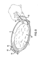
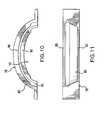
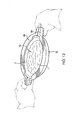
- FIGs. 9-12 Another embodiment is shown in Figs. 9-12 and includes a heating attachment 76 with two attachment halves 78 formed as shells to cooperatively capture and hold the plate 2.
- Each half 78 has a cradle portion 80 providing a support structure, on an internal side of which a microwave shield 82 is mounted, preferably by an adhesion.
- the cradle portions preferably include handle extensions 84 that preferably include attachment surfaces 86, preferably with an adhesive or other attachment member disposed to connect to the opposed cradle portion 80 when the plate 2 is placed in the heating space 74.
- the adhesive on the attachment surfaces 86 can be covered with a removable film 87 to cover the adhesive until the halves 78 are fixed to each other.
- the adhesive surfaces and handle extensions 84 preferably are oriented generally upright and are configured so a user can squeeze the opposing extensions 84 against each other using two hands, as shown in Fig. 12.
- the halves 78 preferably have upper and lower ledges 88,90 or other surfaces to capture and hold the plate 2 in the heating space 74 when the halves 78 are adhered together. To facilitate insertion of the plate 2, the halves are split at the longitudinal ends of the heating space 74.
- the microwave shield 80 is provided along the inside of the interior recess 92 of the halves 78 and preferably extends horizontally around the heating space 74, leaving the bottom and top sides substantially open or substantially free of microwave-reflective material.
- the attachment captures the plate 2, and the attachment preferably has to be broken to release the plate 2, preferably rendering the attachment non-reusable.
- the cradle portions are preferably made of a frangible foam material that is significantly weaker than the adhesive so that the foam and shield 80 brake when the plate 2 is removed, although other suitable materials can be used.
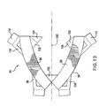
- heating attachment 94 includes a cradle 96, such as of paperboard or a plastic.
- Microwave shield 98 is attached along an elongated portion of the cradle 94 so the cradle 96 provides a degree of stiffness to the shield 98.
- the cradle is preferably symmetrical about a longitudinal axis 100 but can have other shapes depending on the shape of the plate 2 to be held.
- Bottom portions 102 of the cradle are configured to prevent downward extraction of the plate 2 from the heating attachment 94 when associated with the plate 2.
- An attachment extension 104 preferably having adhesive, is provided to connect to the tab 106 of its opposite bottom portion 102, as shown in Fig. 14.
- Upper portions 108 are configured to prevent upward extraction of the plate 2.
- handle extensions 110 Preferably attached to the upper portions 108 are handle extensions 110, which also can include adhesive to attach to the corresponding handle extension 110 or other suitable portion disposed opposite therefrom to close the attachment member 94 about the plate 2 in the operative association.
- the attachment preferably is torn after heating of the food 1 to prevent or hinder reuse, although in an alternative embodiment, the heating attachment may be conducted for removing it from the plate without destroying the heating attachment.
- the microwave shield can extend along bottom portions 102 as well, to provide a more continuous microwave shield around the food product to improve the uniformity of the microwave heating. Even if the shield does extend along bottom portions 102, the coverage on the bottom side of the plate 2, if any, is minor compared to the total area of the bottom side, and the substantial majority of the bottom side preferably remains free of microwave reflective material. Preferably less than about 80%, more preferably less than about 90%, and most preferably less than about 95% of the total bottom side area is shielded with microwave reflective material. In one embodiment, the microwave shield has a small lip that extends over a small distance on the bottom side along most of the periphery thereof.
- the shield promotes propagation of resonant modes of the microwaves in the food product that is in the container in the heating space to improve the uniformity of the microwave heating throughout the food product.
- the preferred attachment members can be packaged in a low-volume configuration to facilitate shipping. In the embodiments of Figs. 4 and 13, the attachment members can be shipped substantially flat, and which in the embodiment of Fig. 9, the two halves of the attachment can be placed with their recesses facing in a same direction to achieve at least partial nesting.
- the microwave shield extends to form a circumferential surface 3 made of a material that is reflective to the microwave is provided that is placed adjacent the sidewall 22 of the plate 2.
- the circumferential surface of reflective material preferably is configured and dimensioned to modify the wavelength in the dielectric food itself.
- the plate 2 has a shape and size that complementarily match the shape and size of the surface 3, although in other embodiments the plate 2 can loosely fit within the closed band 3.
- the band 3 and the heating space 74 preferably has a shape primarily extending in an elongated manner along major axis O.
- the band 3 has a second dimension T that is taken transversally along a transverse axis O' that is substantially oriented orthogonally to a minor axis O, and that preferably passes through the centerline of axial distance A.
- the transverse distance T represents the distance at this centerline between the internal surfaces of the reflective band as measured at a level of the upper surface of the food.
- the distances A and T are preferably measured at the circumference of the band 3 at a level of the upper surface 5 of the food when the food is properly placed in the cavity for re-heating.
- the container is shallow and/or has sidewalls that form a low inclination relative to the bottom surface; e.g., the edges of a dinner plate, the food may usually project upwardly beyond the height of the sidewalls. In that event, the circumference for considering distances A and T will be regarded at the upper edge of the resonating layer.
- the distances A and T of the band are determined to provide a shortening of the wavelength when the food plate, as surrounded by the band 3, is heated in the microwave oven. Therefore, reflection or transfer of the microwave beam is not the primary effect that is sought.
- the primary effect that is sought is related to the modification of the propagation of the waves in the dielectric food material between two or more conductors that support a certain number of electromagnetic waves. These waves have a uniquely defined voltage, current and impedance. Wave guides, often consisting of a single conductor, support transverse electric (TE) and/or transverse magnetic (TM) waves, characterized by the presence of longitudinal magnetic or electric, respectively, field components.
- TE transverse electric
- TM transverse magnetic
- the principle of the invention is to look at determining the boundaries of the band that acts as a wave guide so that high power TE modes of even density are primarily induced. More particularly, TE nm modes of evenly distributed density such as TE 01 , TE 11 , TE 21 are primarily supported while TE nm or TM nm modes of less evenly distributed density such as TE 31 , TE 41 , TE 51 or TM 31 are preferably discarded.
- the transverse distance T of the resonating band should be of about 15 cm or less, preferably lower than about 13 cm, even preferably ranging of about from 6 to 12 cm.
- the axial distance A of the band should be of 20 cm or less, preferably lower than about 18 cm, even preferably ranging of about from 6 to 15 cm.
- the band may comprise tapered surfaces as shown in Fig. 2 and 3 that form an angle ⁇ with respect to the bottom of the plate comprised between about 10 and 120 degrees, preferably, about 15 to 90 degrees, and even more preferably about 20 to 85 degrees. In fact, slightly tapering down surfaces promote a better heating. However, a problem in energy transmission in the bottom of the food may occur if the bottom surface of the plate is reduced, e.g., becomes less than about 5 cm. Therefore, regardless of the inclination of the sidewall, the flat bottom of the plate should be maintained at a transverse dimension of at least about 5 cm, and preferably at least 7 cm.
- the microwave reflective material band should preferably be a continuous or substantially continuous peripheral band of a height of at least about 10 mm, preferably of from about 10 to 60 mm, even preferably of from about 25 to 45 mm.
- gaps in the band can be provided between sections of the band. The gaps are preferably about between 3 mm and 7 mm. Gaps that are too small can cause arcing, while gaps that are too large can reduce the effectiveness of the microwave shield. Any gaps or discontinuities selected preferably are sufficiently large to avoid arcing, while being sufficiently small to preserve the shield's effectiveness.
- the food should preferably be placed so that its upper surface 10 is placed below the upper line 30 of the band 3, preferably at 0 to 15 mm below, even preferably at 2 to 10 mm below.
- the food lower surface 11 contacting the bottom of the plate should be at a level above the lower line 31 of the band of from about 0 to 10 mm, preferably about 0.5 to 5 mm, and more preferably about 2 to 3 mm.
- the transverse distance T and the axial distance A form a diameter that should be preferentially determined, as for the previous example, to be a distance equal to or less than about 15 cm, preferably less than about 13 cm, even preferably of about from 6 to 12 cm.
- the band or layer 3 may preferably comprise a metallic material that is placed adjacent the sidewall 22 of the plate.
- the band may be either attached or simply positioned in close contact with the outer surface of the sidewall 22.
- the band may be positioned adjacent to the inner surface of the sidewall 22 of the plate.
- the band may be a coating material, such as a metal coating, for a cradle or other structural member of the attachment.
- the coating has a thickness that preferably is at least about 3.2 microns, and even more preferably of at least about 10 microns.
- the coating may be applied out by any suitable means such as by vacuum metalizing or chemical etching. Those coating techniques are well known by the man skilled in the art of surface treatment and, therefore, do not need to be described further herein.
- the inside volume and shape demarcated by the circumferential band may be determined to match the external volume and shape of the plate and, therefore, can take a variety of possible cross-sectional configurations, such as parallel, frustoconical or a stepped configuration.
- the portioning and packaging are preferably carried out in a food manufacturing facility utilizing all hygienic and quality standards required in the food manufacturing art.
- the food portions are preferably packaged in a pre-formed package that predetermines the final shape and size of each individual food portion that are subsequently re-heated, and for fitting within the plate 2 of predetermined dimensions.
- the pre-formed package comprises at least one and preferably a plurality of packaging cells.
- the cells forms a plurality of individual cavities wherein each of them have a shape and a size adapted to precisely fit in the cavity of the plate 2 for the microwave re-heating while considering the positioning constraints that have been determined earlier in the present description for obtaining the intended result on uniformity of heating.
- the cavity of the cell should also preferably have an oval contour of predetermined length X and width Y.
- the dimensions X and Y are measured at the outer surface of the food.
- the dimensions X and Y are determined to substantially correspond to the internal dimensions of the heating plate 2 it fits in so that no large gaps are left in the cavity between the product and the plate. It has been noticed that large gaps provide the edge of the food a higher than desired heating. Therefore, gaps, if any, between the product and the inner surface of the plate 2 should be of less than about 8 mm, preferably of less than about 5 mm. Even more preferably, there should be no gap at all between the side surface of the dish and the side surface of the food.
- the contour of the food may have dimensions of X of between about 15 to 19 cm and for Y between about 8 to 15 cm.
- the pre-formed package may be made of a thermoformed plastic foil or any equivalent formable material that can retain a given shape after forming.
- the foil is thermoformed to form the cavities and edges that surround the cavity.
- the material should advantageously be sufficiently deformable to allow easy removal of the food block from the cell.
- the preformed package can be a foodgrade polypropylene or any other suitable plastic of from about 0.1 to 1 mm in thickness.
- a plurality of cell can be formed in a single sheet of plastic as illustrated for cost manufacturing reasons and can be separated along cutting lines, if necessary, or be kept grouped as a collective package, if there is a need for distributing or selling more than one food package at a time.
- the cells can be filled in by food to form the food portions. Depending on the food recipes, freezing may be required before filling in the cells. Freezing may be carried out on discrete food components, for instance, pasta layers, vegetable pieces, meat balls, etc., or on the food block itself whereas other components such as sauce, cheese and the like, may be placed, poured or deposited in the cells at ambient or just at chilled temperature.
- freezing of the filled cells should always be subsequently completed until the whole food portion has reached the frozen temperature range required.
- the food containing cells are usually rapidly cooled to the required freezing temperatures, i.e., minus 18 to 40°C. Freezing may usually be carried out in a spiral freezer or in a freezing tunnel under liquid nitrogen jets or any other suitable freezing technology. Then, the cells may be closed by thin plastic wrap that is sealed onto the edges of the cells or, alternatively, the preformed package 4 may be simply stacked and packed in a cardboard box with a partition film to separate them in the box.
- the cells may also be made of a flexible non-preformed material such as in thin plastic wrap with the shape and size of the cell's cavity to shape the food portion being defined by an external mould.
- the plastic wrap is covered onto the mould surface, the food components are deposited into the plastic wrap and the final block is frozen and removed from the mold.
- the advantage of the packaging cells resides in that packaged food blocks can be mass produced in an inexpensive manner that are properly sized to fit the plate 2.
- the food can, therefore, be transferred from the cell to the ceramic dish to be reheated in a microwave oven and served directly to the consumer in its dish.
- the food portion and plate are preferably sized for a single typical serving that a would be consumed in a desired meal. After food consumption, the plate 2 can thus be washed and re-used as a normal dish.
Landscapes
- Engineering & Computer Science (AREA)
- Food Science & Technology (AREA)
- Mechanical Engineering (AREA)
- Life Sciences & Earth Sciences (AREA)
- Cookers (AREA)
- Package Specialized In Special Use (AREA)
Applications Claiming Priority (2)
| Application Number | Priority Date | Filing Date | Title |
|---|---|---|---|
| US790814 | 2004-03-03 | ||
| US10/790,814 US7491416B2 (en) | 2004-03-03 | 2004-03-03 | Microwave heating attachment |
Publications (1)
| Publication Number | Publication Date |
|---|---|
| EP1571097A1 true EP1571097A1 (fr) | 2005-09-07 |
Family
ID=34750577
Family Applications (1)
| Application Number | Title | Priority Date | Filing Date |
|---|---|---|---|
| EP05002629A Withdrawn EP1571097A1 (fr) | 2004-03-03 | 2005-02-09 | Accessoire pour chauffage à micro-ondes |
Country Status (3)
| Country | Link |
|---|---|
| US (1) | US7491416B2 (fr) |
| EP (1) | EP1571097A1 (fr) |
| AU (1) | AU2005200626B2 (fr) |
Cited By (2)
| Publication number | Priority date | Publication date | Assignee | Title |
|---|---|---|---|---|
| EP1918220A1 (fr) * | 2006-11-03 | 2008-05-07 | Nestec S.A. | Emballage pour le chauffage à micro-ondes |
| NL1041412B1 (nl) * | 2015-07-28 | 2017-02-20 | Boom Packaging B V | De uitvinding heeft betrekking op het gecontroleerd verwarmen van voedingsmiddelen in een magnetron. De uitvinding betreft een onafhankelijke drager van karton of ander materiaal met daarin verwerkt een laag aluminium of ander metaal die de directe straling op de inhoud tegengaat. |
Families Citing this family (12)
| Publication number | Priority date | Publication date | Assignee | Title |
|---|---|---|---|---|
| US7522838B2 (en) * | 2005-10-20 | 2009-04-21 | Fujitsu Limited | Distribution components for a wavelength-sharing network |
| US20090090708A1 (en) * | 2007-10-03 | 2009-04-09 | Emili Requena | Microwave Heating Sleeve |
| EP2493263B1 (fr) * | 2008-07-31 | 2014-06-25 | Graphic Packaging International, Inc. | Construction de chauffage à micro-ondes |
| US20100086639A1 (en) * | 2008-09-07 | 2010-04-08 | Yayu Sophia Pai | Dough Product, Microwaveable Frozen Bread Product, and Method For Making Same |
| JP5496207B2 (ja) * | 2008-09-17 | 2014-05-21 | グラフィック パッケージング インターナショナル インコーポレイテッド | 電子レンジ内で食品を焼き色付けかつカリカリ仕上げするための構造体 |
| US20110024413A1 (en) * | 2008-09-17 | 2011-02-03 | Cole Lorin R | Construct for Browning and Crisping a Food Item in a Microwave Oven |
| US8497455B2 (en) * | 2009-03-11 | 2013-07-30 | Bemis Company, Inc. | Microwave cooking containers with shielding |
| US20110042373A1 (en) * | 2009-08-21 | 2011-02-24 | Kraft Foods Global Brands Llc | Erectable Platform for Microwave Heating of a Food Product |
| KR20120112688A (ko) | 2009-12-30 | 2012-10-11 | 에취.제이.헤인즈캄파니 | 복수 온도 및 복수 재질의 냉동 식품의 마이크로파 가열 트레이 |
| US20150096976A1 (en) * | 2013-10-09 | 2015-04-09 | Conagra Foods Rdm, Inc. | Microwavable food container with at least one removable microwave-interactive robe |
| US20210070526A1 (en) * | 2019-09-06 | 2021-03-11 | Tillamook County Creamery Association | Microwave active packaging for selective heating of contents |
| CN120918385A (zh) * | 2025-09-04 | 2025-11-11 | 中国热带农业科学院农产品加工研究所 | 一种热带水果微波灭菌设备 |
Citations (4)
| Publication number | Priority date | Publication date | Assignee | Title |
|---|---|---|---|---|
| US4874618A (en) * | 1985-12-27 | 1989-10-17 | General Mills, Inc. | Package containing a moisture resistant edible internal barrier |
| US5416304A (en) * | 1990-11-13 | 1995-05-16 | Kraft General Foods, Inc. | Microwave-reflective device and method of use |
| US20010008238A1 (en) * | 1995-10-27 | 2001-07-19 | Witonsky Robert J. | Shielding method for microwave heating of infant formula to a safe and uniform temperature |
| US20030189042A1 (en) * | 2002-04-09 | 2003-10-09 | Hua Zhang | Uniform microwave heating of food in a container |
Family Cites Families (24)
| Publication number | Priority date | Publication date | Assignee | Title |
|---|---|---|---|---|
| US1955663A (en) * | 1933-11-20 | 1934-04-17 | Herman E Wendell | Container |
| US3271169A (en) * | 1963-02-01 | 1966-09-06 | Litton Prec Products Inc | Food package for microwave heating |
| US3547661A (en) * | 1968-10-07 | 1970-12-15 | Teckton Inc | Container and food heating method |
| US3876131A (en) * | 1973-07-02 | 1975-04-08 | Hoerner Waldorf Corp | Wedge shaped carton |
| US4038425A (en) * | 1974-09-25 | 1977-07-26 | The Pillsbury Company | Combined popping and shipping package for popcorn |
| US4096948A (en) * | 1977-03-18 | 1978-06-27 | American Can Company | Cook-in carton with integral removable section and blank therefor |
| SE7907117L (sv) | 1979-08-27 | 1981-02-28 | Findus | Forpackning for livsmedelsprodukter |
| US4425368A (en) * | 1981-07-13 | 1984-01-10 | Golden Valley Foods Inc. | Food heating container |
| US4505391A (en) * | 1983-06-18 | 1985-03-19 | James River-Norwalk, Inc. | Cook-in carton with improved integral support structure |
| US4626641A (en) | 1984-12-04 | 1986-12-02 | James River Corporation | Fruit and meat pie microwave container and method |
| JPS61165526A (ja) * | 1985-01-14 | 1986-07-26 | House Food Ind Co Ltd | 電子レンジ用加熱調理容器 |
| US4661671A (en) * | 1986-01-08 | 1987-04-28 | James River Corporation | Package assembly with heater panel and method for storing and microwave heating of food utilizing same |
| GB8621009D0 (en) * | 1986-08-30 | 1986-10-08 | Waddingtons Cartons Ltd | Heat treatable containers |
| US4705929A (en) * | 1986-12-18 | 1987-11-10 | Somerville Belkin Industries Inc. | Microwave trays |
| US4826072A (en) * | 1988-01-26 | 1989-05-02 | Container Corporation Of America | Microwave carton |
| US4820893A (en) * | 1988-05-02 | 1989-04-11 | Waldorf Corporation | Two-celled expandable microwave cooking sling |
| US4877932A (en) * | 1988-08-15 | 1989-10-31 | International Paper Company | Microwave container assembly |
| US5310980A (en) | 1988-11-28 | 1994-05-10 | Beckett Industries, Inc. | Control of microwave energy in cooking foodstuffs |
| US4965424A (en) * | 1989-05-25 | 1990-10-23 | Mass Market Sales, Inc. | Disposable food container for microwave ovens |
| GB8921754D0 (en) * | 1989-09-27 | 1989-11-08 | Waddingtons Cartons Ltd | Improvements relating to packaging containers |
| US5153402A (en) * | 1990-11-21 | 1992-10-06 | International Paper Company | Paperboard container for microwave cooking |
| US5247149A (en) * | 1991-08-28 | 1993-09-21 | The Stouffer Corporation | Method and appliance for cooking a frozen pizza pie with microwave energy |
| US5288962A (en) * | 1992-11-16 | 1994-02-22 | Conagra Frozen Foods, Inc. | Microwave cooking enclosure for food items |
| JPH06237707A (ja) * | 1993-02-16 | 1994-08-30 | Toppan Printing Co Ltd | マイクロ波加熱用支持体、およびこれを利用した加熱方法、ならびにマイクロ波加熱装置 |
-
2004
- 2004-03-03 US US10/790,814 patent/US7491416B2/en not_active Expired - Fee Related
-
2005
- 2005-02-09 EP EP05002629A patent/EP1571097A1/fr not_active Withdrawn
- 2005-02-11 AU AU2005200626A patent/AU2005200626B2/en not_active Ceased
Patent Citations (4)
| Publication number | Priority date | Publication date | Assignee | Title |
|---|---|---|---|---|
| US4874618A (en) * | 1985-12-27 | 1989-10-17 | General Mills, Inc. | Package containing a moisture resistant edible internal barrier |
| US5416304A (en) * | 1990-11-13 | 1995-05-16 | Kraft General Foods, Inc. | Microwave-reflective device and method of use |
| US20010008238A1 (en) * | 1995-10-27 | 2001-07-19 | Witonsky Robert J. | Shielding method for microwave heating of infant formula to a safe and uniform temperature |
| US20030189042A1 (en) * | 2002-04-09 | 2003-10-09 | Hua Zhang | Uniform microwave heating of food in a container |
Cited By (3)
| Publication number | Priority date | Publication date | Assignee | Title |
|---|---|---|---|---|
| EP1918220A1 (fr) * | 2006-11-03 | 2008-05-07 | Nestec S.A. | Emballage pour le chauffage à micro-ondes |
| WO2008052855A1 (fr) * | 2006-11-03 | 2008-05-08 | Nestec S.A. | Emballage de réchauffage dans un dispositif à micro-ondes |
| NL1041412B1 (nl) * | 2015-07-28 | 2017-02-20 | Boom Packaging B V | De uitvinding heeft betrekking op het gecontroleerd verwarmen van voedingsmiddelen in een magnetron. De uitvinding betreft een onafhankelijke drager van karton of ander materiaal met daarin verwerkt een laag aluminium of ander metaal die de directe straling op de inhoud tegengaat. |
Also Published As
| Publication number | Publication date |
|---|---|
| US20050196491A1 (en) | 2005-09-08 |
| AU2005200626A1 (en) | 2005-09-22 |
| US7491416B2 (en) | 2009-02-17 |
| AU2005200626B2 (en) | 2011-04-14 |
Similar Documents
| Publication | Publication Date | Title |
|---|---|---|
| US20090114644A1 (en) | Uniform microwave heating of food in a container | |
| US7491416B2 (en) | Microwave heating attachment | |
| US4916280A (en) | Food package adapted particularly for microwave heating | |
| CA2638530C (fr) | Contenant alimentaire a plusieurs compartiments pouvant etre chauffe au four a micro-ondes | |
| US20090042705A1 (en) | Multi-Compartment Microwaveable Food Container | |
| WO1995024110A2 (fr) | Emballages alimentaires allant au four | |
| NZ240552A (en) | Frozen food surrounded by microwave reflecting wall | |
| WO1984003815A1 (fr) | Cone de pizza avec remplissage | |
| CN103025624B (zh) | 具有补充食物容器的食物包装 | |
| WO2016187539A2 (fr) | Appareil et procédé d'emballage alimentaire micro-ondable | |
| CN1970397A (zh) | 食品容器 | |
| HK1081930A (en) | Microwave heating attachment | |
| JPH10225377A (ja) | 電子レンジ用調理容器とその食材セット | |
| CA2842929C (fr) | Plateau porte-aliments | |
| JP2024086116A (ja) | 容器入り冷凍食品 | |
| JP2005304382A (ja) | 包装食品と食品の包装調理方法 | |
| JP2005304367A (ja) | 包装食品と食品の包装調理方法 | |
| WO2003004360A2 (fr) | Recipient en carton pour aliments dote d'une section superieure annulaire d'arrachage |
Legal Events
| Date | Code | Title | Description |
|---|---|---|---|
| PUAI | Public reference made under article 153(3) epc to a published international application that has entered the european phase |
Free format text: ORIGINAL CODE: 0009012 |
|
| AK | Designated contracting states |
Kind code of ref document: A1 Designated state(s): AT BE BG CH CY CZ DE DK EE ES FI FR GB GR HU IE IS IT LI LT LU MC NL PL PT RO SE SI SK TR |
|
| AX | Request for extension of the european patent |
Extension state: AL BA HR LV MK YU |
|
| 17P | Request for examination filed |
Effective date: 20060307 |
|
| AKX | Designation fees paid |
Designated state(s): AT BE BG CH CY CZ DE DK EE ES FI FR GB GR HU IE IS IT LI LT LU MC NL PL PT RO SE SI SK TR |
|
| REG | Reference to a national code |
Ref country code: HK Ref legal event code: DE Ref document number: 1081930 Country of ref document: HK |
|
| STAA | Information on the status of an ep patent application or granted ep patent |
Free format text: STATUS: THE APPLICATION IS DEEMED TO BE WITHDRAWN |
|
| 18D | Application deemed to be withdrawn |
Effective date: 20061219 |
|
| REG | Reference to a national code |
Ref country code: HK Ref legal event code: WD Ref document number: 1081930 Country of ref document: HK |