EP1571306A2 - Gicleur pour le refroidissement de piston et outil d'installation - Google Patents
Gicleur pour le refroidissement de piston et outil d'installation Download PDFInfo
- Publication number
- EP1571306A2 EP1571306A2 EP05101594A EP05101594A EP1571306A2 EP 1571306 A2 EP1571306 A2 EP 1571306A2 EP 05101594 A EP05101594 A EP 05101594A EP 05101594 A EP05101594 A EP 05101594A EP 1571306 A2 EP1571306 A2 EP 1571306A2
- Authority
- EP
- European Patent Office
- Prior art keywords
- bore
- main body
- nozzle
- orientation
- cap screw
- Prior art date
- Legal status (The legal status is an assumption and is not a legal conclusion. Google has not performed a legal analysis and makes no representation as to the accuracy of the status listed.)
- Withdrawn
Links
Images


Classifications
-
- F—MECHANICAL ENGINEERING; LIGHTING; HEATING; WEAPONS; BLASTING
- F01—MACHINES OR ENGINES IN GENERAL; ENGINE PLANTS IN GENERAL; STEAM ENGINES
- F01P—COOLING OF MACHINES OR ENGINES IN GENERAL; COOLING OF INTERNAL-COMBUSTION ENGINES
- F01P3/00—Liquid cooling
- F01P3/06—Arrangements for cooling pistons
- F01P3/08—Cooling of piston exterior only, e.g. by jets
-
- F—MECHANICAL ENGINEERING; LIGHTING; HEATING; WEAPONS; BLASTING
- F01—MACHINES OR ENGINES IN GENERAL; ENGINE PLANTS IN GENERAL; STEAM ENGINES
- F01M—LUBRICATING OF MACHINES OR ENGINES IN GENERAL; LUBRICATING INTERNAL COMBUSTION ENGINES; CRANKCASE VENTILATING
- F01M1/00—Pressure lubrication
- F01M1/08—Lubricating systems characterised by the provision therein of lubricant jetting means
Definitions
- the present invention relates to a piston cooling nozzle and installation tool there for.
- each piston can be cooled with a spray of engine oil during operation.
- the piston can be provided with an internal cooling circuit having an oil inlet and an oil outlet wherein the exact orientation of the nozzle is crucial for effective targeting of the spray towards the piston oil inlet during the down-stroke of the piston.
- spray nozzles are frequently secured to a bracket which in turn is bolted to the engine casting, thus obtaining correct orientation via two fixed points. This results in extra hardware, extra manufacturing process and additional costs.
- Such nozzles have means for communicating with the oil gallery of the engine.
- cooling nozzle is a cartridge style arrangement that is inserted in a through-bore from outside the cylinder block.
- the through-bore intersects the oil gallery and an orifice on the cartridge communicates oil from the gallery to the nozzle.
- This arrangement requires o-rings to prevent oil leakage.
- Another type of nozzle mounting arrangement is disclosed in US Patent No. 6,298,810 to Chimonides et al.
- This nozzle consists of an annular mounting collar having a cylindrical outer surface and a tube projecting generally radially from the mounting collar.
- the engine block is formed with a threaded bore that is drilled into the surface of the engine block to intersect the oil gallery.
- a special cap screw is inserted through the collar into the threaded bore to retain the collar to the cylinder block.
- the cap screw has special machining to allow oil to flow from the oil gallery to the nozzle.
- a locating pin is provided to maintain the radial position of the nozzle.
- a piston cooling spray jet and installation tool there for, comprising:
- a cooling nozzle mounting arrangement comprising:
- a cooling nozzle comprising:
- an installation tool comprising:
- a piston cooling spray jet has a hollow main body portion adapted to be press fit into a through bore of the engine cylinder block.
- a first end of the through bore is located in a piston gallery and a second end of the through bore is located in the main bearing journal.
- the through bore intersects with an oil circuit in the cylinder block.
- the main body portion of the nozzle has an orientation feature.
- An installation tool has a main body portion adapted to mateably engage a surface of the main bearing journal.
- a cap screw extends through an aperture in the main body portion, and an orientation key affixed to the main body portion partially surrounds the cap screw.
- the nozzle is inserted into the through bore from a first side in the piston gallery and the installation tool is inserted in the through bore from a second side in the main bearing journal such that the main body portion of the installation tool mateably engages the surface of the main bearing journal, while the cap screw and orientation key are received in the through bore.
- the cap screw is threaded into the interior passage of the main body portion of the nozzle and the orientation key of the installation tool mateably engages the orientation feature of the nozzle so that when the cap screw is tightened to a predetermined torque the nozzle is pulled into the through bore to a predetermined depth and at a predetermined orientation.
- a cooling nozzle mounting arrangement is designated generally by the numeral 10.
- the nozzle mounting arrangement 10 is adapted for use in an internal combustion engine cylinder block 12 such as in a diesel engine for example.
- the cylinder block 12 includes a piston gallery 14 wherein the individual cylinders 16 are located.
- a plurality of main bearing journals 18 are provided in the cylinder block 12.
- the cylinder block 12 further includes an oil circuit 20.
- a through bore 22 is provided in the cylinder block 12 and has a first end 24 located in the piston gallery 14 and a second end 26 located in the main bearing journal 18. The through bore 22 intersects with the oil circuit 20.
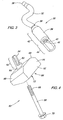
- a cooling nozzle 30 is illustrated in Fig. 3.
- the nozzle 30 includes a nozzle tube 32 affixed to a main body cartridge 34.
- the nozzle tube 32 is a tubular member and may have a serpentine profile as dictated by the particular application and includes a first end generally indicated at 36 and a second end generally indicated at 38. At least a portion of the outside diameter of the nozzle tube 32 proximal to the second end 38 thereof closely approximates the inside diameter of an interior passage 40 in the main body cartridge 34 so that a portion of the nozzle tube 32 can be mateably affixed within the interior passage 40 of the main body cartridge 34 to form the nozzle 30.
- the first end 36 of the nozzle tube 32 can be appropriately adapted to provide a spray pattern as desired for the particular application.
- the main body cartridge 34 of the cooling nozzle 30 has a generally cylindrical portion 42 with the interior passage 40 located therein and having an orientation feature 44 extending from the cylindrical portion 42.
- the orientation feature 44 is a slightly reduced diameter cylinder of which a portion has been machined away so as to leave a semi-cylinder as shown.
- the interior passage 40 of the main body cartridge 34 includes threads 46 at the end proximal to the orientation feature 44. Because the cooling nozzle 30 is adapted to be received in the through bore 22 of the cylinder block 12, the outside diameter of the cylindrical portion 42 of the main body cartridge 34 is selected to attain an appropriate press fit with the through bore 22.
- an installation tool 50 generally includes a main body portion 52, an orientation key 54, and a cap screw 56.
- the main body portion 52 has upper surfaces 58 having a radius that matches the radius of the main bearing journal 18.
- the orientation key 54 is a generally cylindrical member having an interior bore 60.
- the orientation key 54 further includes a semi-cylindrical portion 62 similar to that of the orientation feature 44 described above.
- the orientation key 54 is mounted in an aperture 64 provided in the main body portion 52.
- the cap screw 56 is inserted in the orientation key bore 60 from a first side 66 of the main body portion 52 such that the threaded end 68 extends out from the semi-cylindrical portion 62 of the orientation key 54 and the head 70 can seat against a surface 72 on the first side 66 of the main body portion 52.
- the interior bore 60 of the orientation key 54 is sized so that the cap screw 56 can turn freely when disposed in the bore 60.
- the nozzle 30 is started in the through bore 22 at the first end 24 located in the piston gallery 14. It is preferred to start the nozzle 30 in the bore 22 at as close to the desired final orientation as possible.
- the orientation key 54 and cap screw 56 are then inserted in the through bore 22 at the second end 26 in the main bearing journal 18.
- the radius of the upper surfaces 58 of the main body portion 52 of the tool 50 are then brought into mating engagement with the radius of the main bearing journal 18.
- the sides 74 of the main body portion 52 of the tool 50 are parallel to the sides 76 of the main bearing journal 18 and the orientation key 54 is disposed in the bore 22 at the desired orientation.
- the cap screw 56 is then started in the threads 46 of the interior passage 40 of the nozzle 30.
- the main body cartridge 34 of the nozzle 30 is drawn into a press fit with the through bore 22.
- the mating engagement of the orientation key 54 of the tool 50 with the orientation feature 44 of the nozzle 30 ensures proper orientation of the nozzle 30 within the bore 22 as the cartridge 34 is seated.
- the orientation key 54 of the tool 50 is rigidly affixed to the main body portion 52 and the semi-cylindrical portion 62 of the key 54 is matingly opposed by the semi-cylindrical orientation feature 44 of the nozzle 30, as such the nozzle 30 cannot rotate in the bore 22 as the cap screw 56 is torqued.
- both the orientation key 54 of the tool 50 and the orientation feature 44 of the nozzle 30 are selected based upon the desired final orientation of the nozzle 30 within the piston gallery 14.
- the amount of torque required to fit the nozzle 30 in the bore 22 can be used as a guide to determine when the nozzle 30 is properly located. Once the required torque is determined through experimentation it is simply a matter of tightening the cap screw 56 to the same torque for each nozzle 30 being installed.
- By locating the second end of the through bore 22 in the main bearing journal 18 a convenient alignment is provided by mating the upper surfaces 58 of the tool 50 to the surface radius of the journal. Further, the second end 26 of the through bore 22 is sealed against oil leaks from the oil circuit 20 intersecting the bore 22 when the main bearings are mounted in the main bearing journals 18.
Landscapes
- Engineering & Computer Science (AREA)
- Mechanical Engineering (AREA)
- General Engineering & Computer Science (AREA)
- Chemical & Material Sciences (AREA)
- Combustion & Propulsion (AREA)
- Lubrication Of Internal Combustion Engines (AREA)
Applications Claiming Priority (2)
| Application Number | Priority Date | Filing Date | Title |
|---|---|---|---|
| US791960 | 1991-11-12 | ||
| US10/791,960 US7063049B2 (en) | 2004-03-03 | 2004-03-03 | Directed spray jet and installation tool |
Publications (1)
| Publication Number | Publication Date |
|---|---|
| EP1571306A2 true EP1571306A2 (fr) | 2005-09-07 |
Family
ID=34750593
Family Applications (1)
| Application Number | Title | Priority Date | Filing Date |
|---|---|---|---|
| EP05101594A Withdrawn EP1571306A2 (fr) | 2004-03-03 | 2005-03-02 | Gicleur pour le refroidissement de piston et outil d'installation |
Country Status (3)
| Country | Link |
|---|---|
| US (1) | US7063049B2 (fr) |
| EP (1) | EP1571306A2 (fr) |
| CN (1) | CN1664326A (fr) |
Cited By (1)
| Publication number | Priority date | Publication date | Assignee | Title |
|---|---|---|---|---|
| FR3047769A1 (fr) * | 2016-02-17 | 2017-08-18 | Bontaz Centre R & D | Gicleur d'huile de fabrication simplifiee |
Families Citing this family (9)
| Publication number | Priority date | Publication date | Assignee | Title |
|---|---|---|---|---|
| DE102004019630A1 (de) * | 2004-04-22 | 2005-11-17 | Wacker Construction Equipment Ag | Ölversorgung für einen Verbrennungsmotor |
| US8122859B2 (en) * | 2008-10-22 | 2012-02-28 | Cummins, Inc. | Nylon body located piston cooling nozzle |
| CN102269649B (zh) * | 2010-06-04 | 2013-04-17 | 广西玉柴机器股份有限公司 | 一种发动机活塞冷却喷钩在线试验方法 |
| US8875668B2 (en) | 2012-08-31 | 2014-11-04 | Honda Motor Co., Ltd. | Apparatus configured to shelter oil-jet device from inadvertent installation damage |
| CN105014376B (zh) * | 2015-08-10 | 2017-05-24 | 广西玉柴机器股份有限公司 | 发动机活塞冷却喷钩的辅助装配装置及其装配方法 |
| GB201519640D0 (en) * | 2015-11-06 | 2015-12-23 | Gm Global Tech Operations Inc | Piston cooling jet for an internal combustion engine |
| CN108952922A (zh) * | 2018-07-20 | 2018-12-07 | 江苏农华智慧农业科技股份有限公司 | 一种发动机新材料活塞冷却喷嘴结构及其生产工艺 |
| US11333140B2 (en) * | 2019-06-11 | 2022-05-17 | Caterpillar Inc. | Cooling block for multi-cylinder air compressor |
| US12571330B2 (en) * | 2022-10-27 | 2026-03-10 | Rtx Corporation | Oil nozzle for bearing chamber |
Family Cites Families (4)
| Publication number | Priority date | Publication date | Assignee | Title |
|---|---|---|---|---|
| GB2340578A (en) | 1998-08-13 | 2000-02-23 | Cummins Engine Co Ltd | Mounting a nozzle on an engine block to direct cooling oil at the underside of a reciprocating piston |
| DE10024207A1 (de) * | 2000-05-17 | 2002-01-24 | Man Nutzfahrzeuge Ag | Kolbenkühlung für Brennkraftmaschinen |
| FR2827009B1 (fr) | 2001-07-04 | 2003-12-12 | Bontaz Centre Sa | Gicleur de refroidissement a piston |
| US6526871B1 (en) | 2001-08-24 | 2003-03-04 | Federal-Mogul World Wide, Inc. | Monobloc piston for diesel engines |
-
2004
- 2004-03-03 US US10/791,960 patent/US7063049B2/en not_active Expired - Fee Related
-
2005
- 2005-03-02 EP EP05101594A patent/EP1571306A2/fr not_active Withdrawn
- 2005-03-03 CN CN2005100518863A patent/CN1664326A/zh active Pending
Cited By (5)
| Publication number | Priority date | Publication date | Assignee | Title |
|---|---|---|---|---|
| FR3047769A1 (fr) * | 2016-02-17 | 2017-08-18 | Bontaz Centre R & D | Gicleur d'huile de fabrication simplifiee |
| WO2017140817A1 (fr) * | 2016-02-17 | 2017-08-24 | Bontaz Centre R & D | Gicleur d'huile de fabrication simplifiee |
| CN108603425A (zh) * | 2016-02-17 | 2018-09-28 | 邦达研发中心 | 简化生产的润滑管嘴 |
| US10774700B2 (en) | 2016-02-17 | 2020-09-15 | Bontaz Centre R & D | Lubricating nozzle with simplified production |
| CN108603425B (zh) * | 2016-02-17 | 2020-12-22 | 邦达研发中心 | 简化生产的润滑管嘴 |
Also Published As
| Publication number | Publication date |
|---|---|
| CN1664326A (zh) | 2005-09-07 |
| US20050193964A1 (en) | 2005-09-08 |
| US7063049B2 (en) | 2006-06-20 |
Similar Documents
| Publication | Publication Date | Title |
|---|---|---|
| US4010718A (en) | Reciprocating piston engines having piston oil cooling | |
| US5533472A (en) | Oil jet nozzle for an internal combustion with reciprocating pistons | |
| EP1571306A2 (fr) | Gicleur pour le refroidissement de piston et outil d'installation | |
| US5881684A (en) | Interference fit cooling spray nozzle | |
| CN100366867C (zh) | 安装于气缸壁上的阀 | |
| US7086354B2 (en) | Cooling nozzle mounting arrangement | |
| JPH03194115A (ja) | ピストン冷却アツセンブリー及び高馬力油冷内燃機関 | |
| US20020096138A1 (en) | Cylinder block for an internal combustion engine | |
| US4765543A (en) | Interference connection between a fluid line and a fluid injector | |
| CA2658486C (fr) | Intersection de passages de fluide de moteur et methode | |
| EP0979931B1 (fr) | Montage d'un gicleur de refroidissement sur un bloc moteur | |
| US7836815B2 (en) | Lubricant-cooled and wristpin lubricating piston | |
| CA2323933C (fr) | Ensemble de coussinet et de palier de vilebrequin | |
| US5503116A (en) | Arrangement for supplying liquids to a piston | |
| US20050211089A1 (en) | Lubricant-cooled and wristpin lubricating piston | |
| US5896656A (en) | Method of attaching an internal combustion engine piston oiler | |
| RU2739431C1 (ru) | Система смазки с проходом и насадкой для масла | |
| AU2004226948B2 (en) | Piston cooling nozzle with small distance between axes | |
| JP2002021558A (ja) | 内燃機関のためのピストン冷却装置 | |
| US6792968B1 (en) | Pump assembly and method | |
| US20010037789A1 (en) | Method of manufacturing a monobloc | |
| JPH07139326A (ja) | エンジン動弁機構の潤滑装置 | |
| US5944458A (en) | Boring machine alignment system and method of use | |
| EP1270966B1 (fr) | Vilbrequin pour moteur à combustion | |
| US5423296A (en) | Lubrication system for internal combustion engine |
Legal Events
| Date | Code | Title | Description |
|---|---|---|---|
| PUAI | Public reference made under article 153(3) epc to a published international application that has entered the european phase |
Free format text: ORIGINAL CODE: 0009012 |
|
| AK | Designated contracting states |
Kind code of ref document: A2 Designated state(s): AT BE BG CH CY CZ DE DK EE ES FI FR GB GR HU IE IS IT LI LT LU MC NL PL PT RO SE SI SK TR |
|
| AX | Request for extension of the european patent |
Extension state: AL BA HR LV MK YU |
|
| STAA | Information on the status of an ep patent application or granted ep patent |
Free format text: STATUS: THE APPLICATION HAS BEEN WITHDRAWN |
|
| 18W | Application withdrawn |
Effective date: 20091121 |