EP1571396A2 - Dispositif d'étanchéité pour une chambre de combustion de turbine à gaz - Google Patents
Dispositif d'étanchéité pour une chambre de combustion de turbine à gaz Download PDFInfo
- Publication number
- EP1571396A2 EP1571396A2 EP05101157A EP05101157A EP1571396A2 EP 1571396 A2 EP1571396 A2 EP 1571396A2 EP 05101157 A EP05101157 A EP 05101157A EP 05101157 A EP05101157 A EP 05101157A EP 1571396 A2 EP1571396 A2 EP 1571396A2
- Authority
- EP
- European Patent Office
- Prior art keywords
- sealing
- sealing body
- zone
- body according
- holding
- Prior art date
- Legal status (The legal status is an assumption and is not a legal conclusion. Google has not performed a legal analysis and makes no representation as to the accuracy of the status listed.)
- Granted
Links
Images
Classifications
-
- F—MECHANICAL ENGINEERING; LIGHTING; HEATING; WEAPONS; BLASTING
- F23—COMBUSTION APPARATUS; COMBUSTION PROCESSES
- F23R—GENERATING COMBUSTION PRODUCTS OF HIGH PRESSURE OR HIGH VELOCITY, e.g. GAS-TURBINE COMBUSTION CHAMBERS
- F23R3/00—Continuous combustion chambers using liquid or gaseous fuel
- F23R3/28—Continuous combustion chambers using liquid or gaseous fuel characterised by the fuel supply
-
- F—MECHANICAL ENGINEERING; LIGHTING; HEATING; WEAPONS; BLASTING
- F02—COMBUSTION ENGINES; HOT-GAS OR COMBUSTION-PRODUCT ENGINE PLANTS
- F02C—GAS-TURBINE PLANTS; AIR INTAKES FOR JET-PROPULSION PLANTS; CONTROLLING FUEL SUPPLY IN AIR-BREATHING JET-PROPULSION PLANTS
- F02C7/00—Features, components parts, details or accessories, not provided for in, or of interest apart form groups F02C1/00 - F02C6/00; Air intakes for jet-propulsion plants
- F02C7/28—Arrangement of seals
-
- F—MECHANICAL ENGINEERING; LIGHTING; HEATING; WEAPONS; BLASTING
- F16—ENGINEERING ELEMENTS AND UNITS; GENERAL MEASURES FOR PRODUCING AND MAINTAINING EFFECTIVE FUNCTIONING OF MACHINES OR INSTALLATIONS; THERMAL INSULATION IN GENERAL
- F16J—PISTONS; CYLINDERS; SEALINGS
- F16J15/00—Sealings
- F16J15/02—Sealings between relatively-stationary surfaces
- F16J15/06—Sealings between relatively-stationary surfaces with solid packing compressed between sealing surfaces
- F16J15/08—Sealings between relatively-stationary surfaces with solid packing compressed between sealing surfaces with exclusively metal packing
- F16J15/0887—Sealings between relatively-stationary surfaces with solid packing compressed between sealing surfaces with exclusively metal packing the sealing effect being obtained by elastic deformation of the packing
-
- F—MECHANICAL ENGINEERING; LIGHTING; HEATING; WEAPONS; BLASTING
- F23—COMBUSTION APPARATUS; COMBUSTION PROCESSES
- F23R—GENERATING COMBUSTION PRODUCTS OF HIGH PRESSURE OR HIGH VELOCITY, e.g. GAS-TURBINE COMBUSTION CHAMBERS
- F23R3/00—Continuous combustion chambers using liquid or gaseous fuel
- F23R3/42—Continuous combustion chambers using liquid or gaseous fuel characterised by the arrangement or form of the flame tubes or combustion chambers
- F23R3/60—Support structures; Attaching or mounting means
Definitions
- the present invention relates to a sealing body for sealing a outer member against an inner component, in particular in a Combustion chamber of a gas turbine.
- a gas turbine has a combustion chamber, in particular a Annular combustion chamber or a silo combustion chamber, at least one burner, in particular a premix burner.
- a burner in particular a premix burner.
- such a burner can be equipped with a lance, the through a passage opening formed in a head of the burner extends through and projects into the burner.
- a lance is used for Injecting fuel into the burner or into the combustion chamber.
- the lance In the area of said passage opening, the lance must be opposite to the Be sealed burner to prevent penetration of the hot combustion gases in to avoid a room upstream of the burner.
- Such a seal must be sufficiently elastic in order to operate in the combustion chamber record relative movements between the lance and burner can. On the one hand, these are vibrations that occur during the Operation of the combustion chamber occur, on the other hand it comes at startup and when switching off the combustion chamber or the gas turbine to extreme thermal expansion or shrinkage effects. Finally, the must Seal to withstand the high temperatures occurring during operation.
- the invention as defined in the claims is concerned with the problem of sealing a outer component compared to an inner component a particularly effective Way to show, especially at high temperatures, large thermal expansion effects and vibrations sufficient Functioning has.
- the invention is based on the general idea in the field of Through hole to arrange a sealing body, which is the inner component Contains circumferentially closed and with an inner sealing zone on one Outer sealing surface of the inner component circumferentially closed abuts and with an outer sealing zone on an inner sealing surface of the outer member circumferentially closed.
- the sealing body is at least off a circumferentially closed, band-shaped metal sheet Forming made. This transformation is carried out in such a way that the Sealing body receives the sealing zones exhibiting profile.
- a metal sheet for producing the sealing body is this high temperature and can z. B. occurring during operation of a burner Withstand temperatures.
- the sealing body can also be exposed to relatively large loads and stresses without going too to fail.
- a band-shaped metal sheet for Production of the sealing body can be the inner sealing zone and the outer Sealing zone in profile spaced from each other, whereby the Sealing body between its sealing zones a bending elasticity is feasible, which allows, in the installed state, the sealing zones under bias to the to bring the associated sealing surfaces to the plant.
- the Sealing body of two circumferentially closed, band-shaped and congruent metal parts is made by forming, with this Metal sheets are arranged inside each other and tightly against each other, wherein then the inner sealing zone on the inner panel and the outer sealing zone on Outer sheet is formed.
- this material doubling can be Significantly increase the bending stiffness and thus the achievable biases, at the same time the manufacturability of the seal body by forming remains guaranteed. Since the metal sheets used for this purpose are congruent and after the forming process virtually the same profile have, the two metal sheets in the sealing body by positive locking joined together and thus firmly connected.
- the forming process can be easily carried out so that the two metal sheets then abut each other with high pressure, so the desired To achieve sealing between the individual metal sheets.
- inner panel and Outer sheet with respect to material and / or wall thickness from each other to design differently. This creates the opportunity Inner sheet and outer sheet with respect to different functions and To adapt requirements.
- the inner panel in terms of designed for required mechanical properties of the seal body be such. Strength, elasticity and dimensional stability while in the In contrast, the outer panel in terms of increased thermal and chemical stress of the seal body can be designed, whereby the outer plate works as a kind of protective layer.
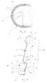
- the sealing body can be at least one Have curved peripheral portion, in which the inner plate and / or the Outer sheet several transverse to the circumferential direction, the respective sheet having or have penetrating slots.
- the formation of slots in the curved peripheral sections simplifies the production of curved peripheral sections by forming. Furthermore, receives the Sealing body through the slots in the curved peripheral sections a increased elasticity, giving a resilient resilience of the Gasket body improved in these peripheral areas.
- both inner panel and outer panel are provided with the slots, can in a development, the slots of the inner panel over the Slots of the outer sheet to be offset in the circumferential direction, so the sheets are sealed between circumferentially adjacent slots abut each other.
- both the Inner panel and the outer panel in the respective curved peripheral portion the improved manufacturability and bending elasticity, whereby by the special staggered arrangement of the inner and outer slots continue to dense System between inner plate and outer plate is guaranteed.
- the profile can after inside resilient springy section prove the outer Press the sealing zone in the installed state against the inner sealing surface.
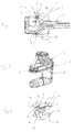
- an inventive sealing body 1 is used for Sealing an outer member 2 against an inner member 3, wherein the inner member 3, the outer member 2 in a through hole. 4 interspersed.
- Sealing body 1 is the outer body 2 to one here only partially shown burner of a combustion chamber, not otherwise shown Gas turbine.
- the inner component 3 is the preferred Application form to a lance through the through hole 4 therethrough or from the passage opening 4 having portion of the burner or the outer component 2 protrudes.
- the lance, so the inner member 3, is used during operation of the combustion chamber for injecting or injecting fuel in the burner or in the combustion chamber.
- the passage opening 4 is on formed a head of the respective burner, from which the lance in the Burner protrudes.
- the outer component 2 has in the region of the passage opening 4 a Inner sealing surface 5, which faces the inner member 3.
- a Outer sealing surface 6 is provided, which faces the outer member 2, See also Fig. 3.
- the seal body 1 is now configured so it has an inner sealing zone 7 and an outer sealing zone 8.
- the sealing body 1 is in the region of Through hole 4 arranged, in such a way that it is the inner member. 3 includes circumferentially closed.
- the inner sealing zone 7 lies circumferentially closed at the outer sealing surface 6.
- the outer sealing zone 8 circumferentially closed on the inner sealing surface 5 at.
- a holding zone 9 is formed on the sealing body 1, which with a formed on the inner member 3 complementary holding portion 10th cooperates and thereby fixes the sealing body 1 on the inner component 3, See Fig. 3. Both the inner sealing zone 7 and the outer Sealing zone 8 are formed in the holding zone 9.
- the sealing body 1 is expediently self-retaining on the inner component. 3 fixable. According to Fig. 3, the sealing body 1 so on the inner member. 3 be pre-assembled. The inner component 3 can then together with the thereto mounted sealing body 1 mounted on the outer member 2, in particular in the passage opening 4 are inserted.
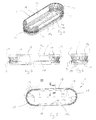
- the sealing body 1 has a peripheral contour which is complementary to a Inner contour of the through hole 4 is formed.
- the circumferential contour of the seal body. 1 be long circular or have a stretched circular shape, so a shape, the from two spaced apart and two parallel Connecting sections interconnected semicircles is.
- B. by the shown here, Angled shape of the lance (inner member 3) be conditional to a Pushing the free lance end through the passage opening 4 to enable.
- Lances can also have elliptical or circular contours for the Through opening 4 and thus for the circumference of the seal body. 1 be provided.
- the sealing body 1 consists of at least one metal sheet 11 produced by deformation, the band-shaped and in the circumferential direction closed is.
- the seal body 1 is made of a cylindrical sleeve-shaped sheet-metal body produced in the circumferential direction closed is. The transformation is carried out appropriately by means of a corresponding rolling process. Due to the desired elasticity and Strength properties precipitate casting process. Nor can the Sealing body 1 are deep-drawn due to the desired profiling. In contrast, the seal body 1 may be alternative to roll forming also produced by hydroforming or hydroforming become.
- the sealing body 1 is replaced by the respective one Forming a profile 12.
- This profile 12 is shaped so that it along the entire circumference of the sealing body 1, the inner sealing zone 7 and spaced from the outer sealing zone 8 has or forms.
- the profile 12 at least in a peripheral portion of the sealing body 1 the holding zone 9 is formed, which in Fig. 9 by a brace is marked.
- the outer sealing zone 8 is in the profile 12 by an after outside, so to the inner sealing surface 5 of the outer member 2 out convex Curvature formed.
- the outer member 2 with a cylindrical, in particular circular cylindrical, inner sealing surface 5 is provided.
- the profile 12 is in the preferred embodiment shown here with a Spring section 13 equipped in Fig. 9 by a brace is marked.
- This spring portion 13 is at least inward resiliently resilient and has a distance from the inner sealing zone 7 a Support zone 20 on.
- the holding zone 9 in profile as a C-shaped Be formed clip.
- This clamp (holding zone 9) has two inwardly angled holding portions 14, 15 which are opposite and in the installed state, the holding portion 10 of the inner member 3 at two embrace the opposite sides.
- the holding area 10 formed as outwardly projecting retaining collar.
- the Holding zone 9 between the two holding portions 14, 15 shaped so that a spring 16 is formed.
- This spring 16 can be the two Holding portions 14, 15 bias each other or in the installed state against Press the retaining collar (holding area 10). This results in a backlash-free fixation of the seal body 1 on the second component 3. At the same time This can compensate for manufacturing tolerances in the insertion become.
- the spring 16 also allows a prestressed Plant the inner sealing zone 7 on the outer sealing surface 6 at a appropriate adjustment of the dimensioning of the seal body 1 to the Dimension of the outer sealing surface 6. At the same time is thereby also a Compensation of tolerances occurring transversely to the direction of insertion allows.
- the dimensioning of the spring section 13 can for example be done so a distance between the support zone 20 and the sealing zones 7 and 8 between a radius of curvature of the semicircular curved Circumferential sections 17 and a distance of the two rectilinear Circumferential sections 18 is located.
- one of the holding portions 14, 15, here denoted by 14 Holding portion formed at a free end of the profile 12 and inwards angled.
- the peripheral contour has of the sealing body 1 two semicircular curved peripheral portions 17th and two rectilinear circumferential portions 18 which are parallel to each other and the two semicircular curved peripheral portions 17 connect with each other.
- the free End of the profile 12 trained holding section 14 exclusively on the two rectilinear peripheral portions 18 formed, with the result that the Holding zone 9 or the bracket only in the region of this rectilinear Perimeter sections 18 is formed on the profile 12.
- holding portion 9 in principle also be configured can that the sealing body 1 so that self-holding on the outer component. 2 can be fixed.
- the seal body 1 in operation can be very high Forces and / or moments to be delivered. To make these loads elastic To be able to catch the seal body 1 requires a relatively large Spring stiffness.
- the achievable by deformation curvature radii hang However, from the material thickness of the metal sheet 11 used. The fat of the metal sheet 11 limited down the achievable radii of curvature.
- these metal sheets 11i, 11a are intermeshed arranged and close to each other.
- the two metal sheets 11i, 11a results for the sealing body 1 a two-layer composite construction.
- the two metal sheets 11i, 11a are in the Forming for the production of the sealing body 1 relative to each other movable, what the achievement of smaller radii of curvature favors. At the same time they form Materialdopplept, which a mutual stiffening and thus a cause increased spring stiffness.
- the two metal sheets extend 11i and 11a over the entire length of the profile 12 congruent. Due to the the selected profiling results in an intensive form fit between the two sheets 11i, 11a, whereby the two sheets 11i, 11a fixed connected to each other without any additional fastening measures required are. Nevertheless, additional fastening measures, such. B. Soldering and / or welding, not excluded.
- curved peripheral portions 17 on the seal body 1 is for a forcibly, since the seal body 1, the internal component. 3 must completely surround circumferentially. On the other hand, that reduces Curvature in combination with the chosen profiling the elasticity of the spring Profile 12 in these curved peripheral portions 17. Since the Sealing body 1 but also in its curved peripheral portions 17th spring elastic response to relative movements between components 2, 3 and To maintain its sealing effect, it is desirable to the spring elasticity in To increase the area of the curved peripheral portions 17. This is achieved in the sealing body 1 according to the invention by means of slots 19, which in the respective curved peripheral portion 17 are formed, transversely to Run circumferentially and the respective sheet 11i, 11a penetrate. These Slots 19 extend until directly on or in front of the sealing zones 7 and 8 of the seal body 1. The slots 19 are used in the manufacture of the Sealing body 1 before forming the respective metal sheet 11th appropriate.
- both are Inner panel 11i and the outer panel 11a equipped with the slots 19.
- only the inner panel 11i or only the outer panel 11 a be equipped with the slots 19.
- the respective metal sheet 11th quasi segmented, whereby the spring elasticity of the seal body 1 in this curved peripheral portion 17 is significantly increased. That is, in curved peripheral portions 17, the seal body 1 at clearly yield elastically to larger deformation paths.
- the slots are 19 so positioned on the sheets 11i, 11a and are inner sheet 11i and Outer sheet 11a relative to each other positioned so that the slots 19 of the Inner plate 11i opposite the slots 19 of the outer panel 11a in Circumferentially arranged offset from each other.
- the Slots 19 of the inner panel 11i each centrally between two slots 19 of the Outer sheet 11a arranged.
- each slot 19 of the outer panel 11a by a lying between adjacent slots 19 of the inner panel 9i Covered wall segment.
- each slot 19 of the Inner plate 11i through an between adjacent slots 19 of the outer panel Covered 11a lying wall segment.
- the metal sheet 11 respectively used for producing the sealing body 1, in particular the inner panel 11i and the outer panel 11a, is preferably made in one piece from one piece. As a result, the sealing body 1 receives a very high strength
- the inner panel 11 i and the Outer sheet 11a are adapted to different functions.
- the inner panel 11i serves to seal the body 1 required mechanical stability, strength, rigidity and elasticity give.
- the outer panel 11a may be used as a protective layer serve and for this purpose an increased thermal and / or chemical resistance exhibit.
Landscapes
- Engineering & Computer Science (AREA)
- General Engineering & Computer Science (AREA)
- Mechanical Engineering (AREA)
- Chemical & Material Sciences (AREA)
- Combustion & Propulsion (AREA)
- Gasket Seals (AREA)
Applications Claiming Priority (2)
| Application Number | Priority Date | Filing Date | Title |
|---|---|---|---|
| DE102004010422 | 2004-03-01 | ||
| DE102004010422A DE102004010422A1 (de) | 2004-03-01 | 2004-03-01 | Dichtungskörper |
Publications (3)
| Publication Number | Publication Date |
|---|---|
| EP1571396A2 true EP1571396A2 (fr) | 2005-09-07 |
| EP1571396A3 EP1571396A3 (fr) | 2013-07-24 |
| EP1571396B1 EP1571396B1 (fr) | 2017-06-28 |
Family
ID=34745370
Family Applications (1)
| Application Number | Title | Priority Date | Filing Date |
|---|---|---|---|
| EP05101157.5A Expired - Lifetime EP1571396B1 (fr) | 2004-03-01 | 2005-02-16 | Dispositif d'étanchéité pour une chambre de combustion de turbine à gaz |
Country Status (4)
| Country | Link |
|---|---|
| US (1) | US7631501B2 (fr) |
| EP (1) | EP1571396B1 (fr) |
| DE (1) | DE102004010422A1 (fr) |
| ES (1) | ES2639562T3 (fr) |
Cited By (1)
| Publication number | Priority date | Publication date | Assignee | Title |
|---|---|---|---|---|
| EP2253888A1 (fr) * | 2009-05-14 | 2010-11-24 | Alstom Technology Ltd | Brûleur d'une turbine à gaz |
Families Citing this family (5)
| Publication number | Priority date | Publication date | Assignee | Title |
|---|---|---|---|---|
| FR2933160B1 (fr) * | 2008-06-25 | 2010-09-10 | Commissariat Energie Atomique | Assemblage comportant un joint d'etancheite intercale entre deux composants de coefficient de dilatation moyen thermique different, joint d'etancheite associe, application a l'etancheite d'electrolyseurs eht et des piles a combustible |
| US9790863B2 (en) | 2013-04-05 | 2017-10-17 | Honeywell International Inc. | Fluid transfer seal assemblies, fluid transfer systems, and methods for transferring process fluid between stationary and rotating components using the same |
| US20150316011A1 (en) * | 2014-05-05 | 2015-11-05 | Electro-Motive Diesel, Inc. | Sealing body for isolating vibrations from cylinder body to nozzle |
| US11473437B2 (en) * | 2015-09-24 | 2022-10-18 | General Electric Company | Turbine snap in spring seal |
| GB2548585B (en) | 2016-03-22 | 2020-05-27 | Rolls Royce Plc | A combustion chamber assembly |
Family Cites Families (6)
| Publication number | Priority date | Publication date | Assignee | Title |
|---|---|---|---|---|
| US3759038A (en) * | 1971-12-09 | 1973-09-18 | Westinghouse Electric Corp | Self aligning combustor and transition structure for a gas turbine |
| US4712370A (en) * | 1986-04-24 | 1987-12-15 | The United States Of America As Represented By The Secretary Of The Air Force | Sliding duct seal |
| JP3999616B2 (ja) * | 2002-09-24 | 2007-10-31 | 本田技研工業株式会社 | 差し込み構造体 |
| US7093837B2 (en) * | 2002-09-26 | 2006-08-22 | Siemens Westinghouse Power Corporation | Turbine spring clip seal |
| US6880341B2 (en) * | 2002-12-18 | 2005-04-19 | Pratt & Whitney Canada Corp. | Low cost combustor floating collar with improved sealing and damping |
| US6869082B2 (en) * | 2003-06-12 | 2005-03-22 | Siemens Westinghouse Power Corporation | Turbine spring clip seal |
-
2004
- 2004-03-01 DE DE102004010422A patent/DE102004010422A1/de not_active Withdrawn
-
2005
- 2005-02-16 EP EP05101157.5A patent/EP1571396B1/fr not_active Expired - Lifetime
- 2005-02-16 ES ES05101157.5T patent/ES2639562T3/es not_active Expired - Lifetime
- 2005-03-01 US US11/067,722 patent/US7631501B2/en active Active
Cited By (2)
| Publication number | Priority date | Publication date | Assignee | Title |
|---|---|---|---|---|
| EP2253888A1 (fr) * | 2009-05-14 | 2010-11-24 | Alstom Technology Ltd | Brûleur d'une turbine à gaz |
| US9726377B2 (en) | 2009-05-14 | 2017-08-08 | Ansaldo Energia Switzerland AG | Burner of a gas turbine |
Also Published As
| Publication number | Publication date |
|---|---|
| US20050235647A1 (en) | 2005-10-27 |
| DE102004010422A1 (de) | 2005-09-22 |
| EP1571396A3 (fr) | 2013-07-24 |
| EP1571396B1 (fr) | 2017-06-28 |
| ES2639562T3 (es) | 2017-10-27 |
| US7631501B2 (en) | 2009-12-15 |
Similar Documents
| Publication | Publication Date | Title |
|---|---|---|
| EP0582985B1 (fr) | Collecteur d'échappement | |
| DE102009025054A1 (de) | Turbinengehäuse | |
| DE2412567C3 (de) | Katalytischer Abgasentgifter | |
| DE202010013507U1 (de) | Hitzeschild | |
| EP2299087A2 (fr) | Turbocompresseur | |
| DE202008010025U1 (de) | Metallische Dichtung, insbesondere Abgaskrümmerdichtung | |
| DE102007062681A1 (de) | Dichtsegment sowie Dichtsegmentenanordnung | |
| EP0508145B1 (fr) | Conduit d'échappement isolé par une couche d'air | |
| EP2238314A1 (fr) | Dispositif de fixation axiale d aubes mobiles dans le rotor d une turbine à gaz | |
| EP1862709B1 (fr) | Joint de tête de cylindre | |
| EP1571396B1 (fr) | Dispositif d'étanchéité pour une chambre de combustion de turbine à gaz | |
| DE8236692U1 (de) | Dichtungsanordnung zur gelenkigen verbindung von zwei rohrleitungen, insbesondere heissgehenden abgasleitungen | |
| EP0406730B1 (fr) | Joint de culasse de cylindre | |
| DE102015206251A1 (de) | Metall-Balg und Verfahren zu dessen Herstellung | |
| DE3935960C2 (de) | Einrichtung zur abdichtenden Überbrückung eines Spaltes zwischen zwei in drei Raumrichtungen verschiebbaren Bauteilen | |
| DE202018102108U1 (de) | Abgasleitungselement | |
| DE9414941U1 (de) | Metallische Flachdichtung | |
| DE19816692A1 (de) | Brennkammerdichtungsanordnung mit hohem Rückstellungsvermögen | |
| DE602004009646T2 (de) | Dichtung mit flexiblem Stopper | |
| WO2025162894A1 (fr) | Structure de support pour une unité de post-traitement de gaz d'échappement et dispositif présentant un corps en nid d'abeilles et une structure de support | |
| DE102008049253B4 (de) | Kfz-Abgaskühler | |
| DE2301646A1 (de) | Katalysatortopf fuer abgasleitungen | |
| EP0939270B1 (fr) | Dispositif avec un tube à jet | |
| DE4214514A1 (de) | Flansch, insbesondere zur befestigung von abgasrohren | |
| DE102004023442B4 (de) | Halterungsvorrichtung |
Legal Events
| Date | Code | Title | Description |
|---|---|---|---|
| PUAI | Public reference made under article 153(3) epc to a published international application that has entered the european phase |
Free format text: ORIGINAL CODE: 0009012 |
|
| AK | Designated contracting states |
Kind code of ref document: A2 Designated state(s): AT BE BG CH CY CZ DE DK EE ES FI FR GB GR HU IE IS IT LI LT LU MC NL PL PT RO SE SI SK TR |
|
| AX | Request for extension of the european patent |
Extension state: AL BA HR LV MK YU |
|
| PUAL | Search report despatched |
Free format text: ORIGINAL CODE: 0009013 |
|
| AK | Designated contracting states |
Kind code of ref document: A3 Designated state(s): AT BE BG CH CY CZ DE DK EE ES FI FR GB GR HU IE IS IT LI LT LU MC NL PL PT RO SE SI SK TR |
|
| AX | Request for extension of the european patent |
Extension state: AL BA HR LV MK YU |
|
| RIC1 | Information provided on ipc code assigned before grant |
Ipc: F23R 3/28 20060101AFI20130614BHEP Ipc: F16J 15/08 20060101ALI20130614BHEP Ipc: F23R 3/60 20060101ALN20130614BHEP Ipc: F02C 7/28 20060101ALI20130614BHEP |
|
| 17P | Request for examination filed |
Effective date: 20131023 |
|
| RBV | Designated contracting states (corrected) |
Designated state(s): AT BE BG CH CY CZ DE DK EE ES FI FR GB GR HU IE IS IT LI LT LU MC NL PL PT RO SE SI SK TR |
|
| AKX | Designation fees paid |
Designated state(s): AT BE BG CH CY CZ DE DK EE ES FI FR GB GR HU IE IS IT LI LT LU MC NL PL PT RO SE SI SK TR |
|
| 17Q | First examination report despatched |
Effective date: 20150918 |
|
| RAP1 | Party data changed (applicant data changed or rights of an application transferred) |
Owner name: GENERAL ELECTRIC TECHNOLOGY GMBH |
|
| GRAP | Despatch of communication of intention to grant a patent |
Free format text: ORIGINAL CODE: EPIDOSNIGR1 |
|
| INTG | Intention to grant announced |
Effective date: 20170119 |
|
| GRAS | Grant fee paid |
Free format text: ORIGINAL CODE: EPIDOSNIGR3 |
|
| GRAA | (expected) grant |
Free format text: ORIGINAL CODE: 0009210 |
|
| RAP1 | Party data changed (applicant data changed or rights of an application transferred) |
Owner name: ANSALDO ENERGIA SWITZERLAND AG |
|
| AK | Designated contracting states |
Kind code of ref document: B1 Designated state(s): AT BE BG CH CY CZ DE DK EE ES FI FR GB GR HU IE IS IT LI LT LU MC NL PL PT RO SE SI SK TR |
|
| REG | Reference to a national code |
Ref country code: GB Ref legal event code: FG4D Free format text: NOT ENGLISH |
|
| REG | Reference to a national code |
Ref country code: CH Ref legal event code: EP |
|
| REG | Reference to a national code |
Ref country code: AT Ref legal event code: REF Ref document number: 905215 Country of ref document: AT Kind code of ref document: T Effective date: 20170715 |
|
| REG | Reference to a national code |
Ref country code: IE Ref legal event code: FG4D Free format text: LANGUAGE OF EP DOCUMENT: GERMAN |
|
| REG | Reference to a national code |
Ref country code: DE Ref legal event code: R096 Ref document number: 502005015635 Country of ref document: DE |
|
| REG | Reference to a national code |
Ref country code: ES Ref legal event code: FG2A Ref document number: 2639562 Country of ref document: ES Kind code of ref document: T3 Effective date: 20171027 |
|
| PG25 | Lapsed in a contracting state [announced via postgrant information from national office to epo] |
Ref country code: FI Free format text: LAPSE BECAUSE OF FAILURE TO SUBMIT A TRANSLATION OF THE DESCRIPTION OR TO PAY THE FEE WITHIN THE PRESCRIBED TIME-LIMIT Effective date: 20170628 Ref country code: GR Free format text: LAPSE BECAUSE OF FAILURE TO SUBMIT A TRANSLATION OF THE DESCRIPTION OR TO PAY THE FEE WITHIN THE PRESCRIBED TIME-LIMIT Effective date: 20170929 Ref country code: LT Free format text: LAPSE BECAUSE OF FAILURE TO SUBMIT A TRANSLATION OF THE DESCRIPTION OR TO PAY THE FEE WITHIN THE PRESCRIBED TIME-LIMIT Effective date: 20170628 |
|
| REG | Reference to a national code |
Ref country code: NL Ref legal event code: MP Effective date: 20170628 |
|
| REG | Reference to a national code |
Ref country code: LT Ref legal event code: MG4D |
|
| PG25 | Lapsed in a contracting state [announced via postgrant information from national office to epo] |
Ref country code: BG Free format text: LAPSE BECAUSE OF FAILURE TO SUBMIT A TRANSLATION OF THE DESCRIPTION OR TO PAY THE FEE WITHIN THE PRESCRIBED TIME-LIMIT Effective date: 20170928 Ref country code: NL Free format text: LAPSE BECAUSE OF FAILURE TO SUBMIT A TRANSLATION OF THE DESCRIPTION OR TO PAY THE FEE WITHIN THE PRESCRIBED TIME-LIMIT Effective date: 20170628 Ref country code: SE Free format text: LAPSE BECAUSE OF FAILURE TO SUBMIT A TRANSLATION OF THE DESCRIPTION OR TO PAY THE FEE WITHIN THE PRESCRIBED TIME-LIMIT Effective date: 20170628 |
|
| PG25 | Lapsed in a contracting state [announced via postgrant information from national office to epo] |
Ref country code: EE Free format text: LAPSE BECAUSE OF FAILURE TO SUBMIT A TRANSLATION OF THE DESCRIPTION OR TO PAY THE FEE WITHIN THE PRESCRIBED TIME-LIMIT Effective date: 20170628 Ref country code: RO Free format text: LAPSE BECAUSE OF FAILURE TO SUBMIT A TRANSLATION OF THE DESCRIPTION OR TO PAY THE FEE WITHIN THE PRESCRIBED TIME-LIMIT Effective date: 20170628 Ref country code: SK Free format text: LAPSE BECAUSE OF FAILURE TO SUBMIT A TRANSLATION OF THE DESCRIPTION OR TO PAY THE FEE WITHIN THE PRESCRIBED TIME-LIMIT Effective date: 20170628 Ref country code: CZ Free format text: LAPSE BECAUSE OF FAILURE TO SUBMIT A TRANSLATION OF THE DESCRIPTION OR TO PAY THE FEE WITHIN THE PRESCRIBED TIME-LIMIT Effective date: 20170628 |
|
| PG25 | Lapsed in a contracting state [announced via postgrant information from national office to epo] |
Ref country code: PL Free format text: LAPSE BECAUSE OF FAILURE TO SUBMIT A TRANSLATION OF THE DESCRIPTION OR TO PAY THE FEE WITHIN THE PRESCRIBED TIME-LIMIT Effective date: 20170628 Ref country code: IS Free format text: LAPSE BECAUSE OF FAILURE TO SUBMIT A TRANSLATION OF THE DESCRIPTION OR TO PAY THE FEE WITHIN THE PRESCRIBED TIME-LIMIT Effective date: 20171028 |
|
| REG | Reference to a national code |
Ref country code: DE Ref legal event code: R097 Ref document number: 502005015635 Country of ref document: DE |
|
| PG25 | Lapsed in a contracting state [announced via postgrant information from national office to epo] |
Ref country code: DK Free format text: LAPSE BECAUSE OF FAILURE TO SUBMIT A TRANSLATION OF THE DESCRIPTION OR TO PAY THE FEE WITHIN THE PRESCRIBED TIME-LIMIT Effective date: 20170628 |
|
| PLBE | No opposition filed within time limit |
Free format text: ORIGINAL CODE: 0009261 |
|
| STAA | Information on the status of an ep patent application or granted ep patent |
Free format text: STATUS: NO OPPOSITION FILED WITHIN TIME LIMIT |
|
| 26N | No opposition filed |
Effective date: 20180329 |
|
| PG25 | Lapsed in a contracting state [announced via postgrant information from national office to epo] |
Ref country code: SI Free format text: LAPSE BECAUSE OF FAILURE TO SUBMIT A TRANSLATION OF THE DESCRIPTION OR TO PAY THE FEE WITHIN THE PRESCRIBED TIME-LIMIT Effective date: 20170628 |
|
| REG | Reference to a national code |
Ref country code: CH Ref legal event code: PL |
|
| PG25 | Lapsed in a contracting state [announced via postgrant information from national office to epo] |
Ref country code: MC Free format text: LAPSE BECAUSE OF FAILURE TO SUBMIT A TRANSLATION OF THE DESCRIPTION OR TO PAY THE FEE WITHIN THE PRESCRIBED TIME-LIMIT Effective date: 20170628 |
|
| REG | Reference to a national code |
Ref country code: IE Ref legal event code: MM4A |
|
| REG | Reference to a national code |
Ref country code: BE Ref legal event code: MM Effective date: 20180228 |
|
| PG25 | Lapsed in a contracting state [announced via postgrant information from national office to epo] |
Ref country code: LI Free format text: LAPSE BECAUSE OF NON-PAYMENT OF DUE FEES Effective date: 20180228 Ref country code: LU Free format text: LAPSE BECAUSE OF NON-PAYMENT OF DUE FEES Effective date: 20180216 Ref country code: CH Free format text: LAPSE BECAUSE OF NON-PAYMENT OF DUE FEES Effective date: 20180228 |
|
| REG | Reference to a national code |
Ref country code: FR Ref legal event code: ST Effective date: 20181031 |
|
| PG25 | Lapsed in a contracting state [announced via postgrant information from national office to epo] |
Ref country code: IE Free format text: LAPSE BECAUSE OF NON-PAYMENT OF DUE FEES Effective date: 20180216 |
|
| PG25 | Lapsed in a contracting state [announced via postgrant information from national office to epo] |
Ref country code: FR Free format text: LAPSE BECAUSE OF NON-PAYMENT OF DUE FEES Effective date: 20180228 Ref country code: BE Free format text: LAPSE BECAUSE OF NON-PAYMENT OF DUE FEES Effective date: 20180228 |
|
| REG | Reference to a national code |
Ref country code: AT Ref legal event code: MM01 Ref document number: 905215 Country of ref document: AT Kind code of ref document: T Effective date: 20180216 |
|
| PG25 | Lapsed in a contracting state [announced via postgrant information from national office to epo] |
Ref country code: AT Free format text: LAPSE BECAUSE OF NON-PAYMENT OF DUE FEES Effective date: 20180216 |
|
| REG | Reference to a national code |
Ref country code: ES Ref legal event code: FD2A Effective date: 20190801 |
|
| PG25 | Lapsed in a contracting state [announced via postgrant information from national office to epo] |
Ref country code: ES Free format text: LAPSE BECAUSE OF NON-PAYMENT OF DUE FEES Effective date: 20180217 |
|
| PG25 | Lapsed in a contracting state [announced via postgrant information from national office to epo] |
Ref country code: TR Free format text: LAPSE BECAUSE OF FAILURE TO SUBMIT A TRANSLATION OF THE DESCRIPTION OR TO PAY THE FEE WITHIN THE PRESCRIBED TIME-LIMIT Effective date: 20170628 |
|
| PG25 | Lapsed in a contracting state [announced via postgrant information from national office to epo] |
Ref country code: HU Free format text: LAPSE BECAUSE OF FAILURE TO SUBMIT A TRANSLATION OF THE DESCRIPTION OR TO PAY THE FEE WITHIN THE PRESCRIBED TIME-LIMIT; INVALID AB INITIO Effective date: 20050216 Ref country code: PT Free format text: LAPSE BECAUSE OF FAILURE TO SUBMIT A TRANSLATION OF THE DESCRIPTION OR TO PAY THE FEE WITHIN THE PRESCRIBED TIME-LIMIT Effective date: 20170628 |
|
| PG25 | Lapsed in a contracting state [announced via postgrant information from national office to epo] |
Ref country code: CY Free format text: LAPSE BECAUSE OF FAILURE TO SUBMIT A TRANSLATION OF THE DESCRIPTION OR TO PAY THE FEE WITHIN THE PRESCRIBED TIME-LIMIT Effective date: 20170628 |
|
| PGFP | Annual fee paid to national office [announced via postgrant information from national office to epo] |
Ref country code: GB Payment date: 20220223 Year of fee payment: 18 Ref country code: DE Payment date: 20220217 Year of fee payment: 18 |
|
| PGFP | Annual fee paid to national office [announced via postgrant information from national office to epo] |
Ref country code: IT Payment date: 20220218 Year of fee payment: 18 |
|
| REG | Reference to a national code |
Ref country code: DE Ref legal event code: R119 Ref document number: 502005015635 Country of ref document: DE |
|
| GBPC | Gb: european patent ceased through non-payment of renewal fee |
Effective date: 20230216 |
|
| PG25 | Lapsed in a contracting state [announced via postgrant information from national office to epo] |
Ref country code: GB Free format text: LAPSE BECAUSE OF NON-PAYMENT OF DUE FEES Effective date: 20230216 |
|
| PG25 | Lapsed in a contracting state [announced via postgrant information from national office to epo] |
Ref country code: IT Free format text: LAPSE BECAUSE OF NON-PAYMENT OF DUE FEES Effective date: 20230216 Ref country code: GB Free format text: LAPSE BECAUSE OF NON-PAYMENT OF DUE FEES Effective date: 20230216 Ref country code: DE Free format text: LAPSE BECAUSE OF NON-PAYMENT OF DUE FEES Effective date: 20230901 |