EP1574626B1 - Système hydraulique de suspension passive - Google Patents
Système hydraulique de suspension passive Download PDFInfo
- Publication number
- EP1574626B1 EP1574626B1 EP05101766A EP05101766A EP1574626B1 EP 1574626 B1 EP1574626 B1 EP 1574626B1 EP 05101766 A EP05101766 A EP 05101766A EP 05101766 A EP05101766 A EP 05101766A EP 1574626 B1 EP1574626 B1 EP 1574626B1
- Authority
- EP
- European Patent Office
- Prior art keywords
- hydraulic
- switching
- valve
- chamber
- suspension system
- Prior art date
- Legal status (The legal status is an assumption and is not a legal conclusion. Google has not performed a legal analysis and makes no representation as to the accuracy of the status listed.)
- Not-in-force
Links
- 239000000725 suspension Substances 0.000 title claims description 63
- 230000007935 neutral effect Effects 0.000 claims description 33
- 239000012530 fluid Substances 0.000 claims description 5
- 230000004913 activation Effects 0.000 description 7
- 238000000034 method Methods 0.000 description 4
- 230000035939 shock Effects 0.000 description 4
- 238000012806 monitoring device Methods 0.000 description 3
- 230000001133 acceleration Effects 0.000 description 2
- 230000008901 benefit Effects 0.000 description 2
- 230000006835 compression Effects 0.000 description 2
- 238000007906 compression Methods 0.000 description 2
- 230000002950 deficient Effects 0.000 description 2
- 230000005284 excitation Effects 0.000 description 2
- 238000012986 modification Methods 0.000 description 2
- 230000004048 modification Effects 0.000 description 2
- 230000008569 process Effects 0.000 description 2
- 241000272525 Anas platyrhynchos Species 0.000 description 1
- 230000003213 activating effect Effects 0.000 description 1
- 230000009849 deactivation Effects 0.000 description 1
- 230000001419 dependent effect Effects 0.000 description 1
- 238000013461 design Methods 0.000 description 1
- 238000011161 development Methods 0.000 description 1
- 230000018109 developmental process Effects 0.000 description 1
- 230000000694 effects Effects 0.000 description 1
- 238000011156 evaluation Methods 0.000 description 1
- 230000002349 favourable effect Effects 0.000 description 1
- 230000007257 malfunction Effects 0.000 description 1
- 230000007246 mechanism Effects 0.000 description 1
- 238000012544 monitoring process Methods 0.000 description 1
Images

Classifications
-
- E—FIXED CONSTRUCTIONS
- E02—HYDRAULIC ENGINEERING; FOUNDATIONS; SOIL SHIFTING
- E02F—DREDGING; SOIL-SHIFTING
- E02F9/00—Component parts of dredgers or soil-shifting machines, not restricted to one of the kinds covered by groups E02F3/00 - E02F7/00
- E02F9/20—Drives; Control devices
- E02F9/22—Hydraulic or pneumatic drives
- E02F9/2217—Hydraulic or pneumatic drives with energy recovery arrangements, e.g. using accumulators, flywheels
-
- E—FIXED CONSTRUCTIONS
- E02—HYDRAULIC ENGINEERING; FOUNDATIONS; SOIL SHIFTING
- E02F—DREDGING; SOIL-SHIFTING
- E02F9/00—Component parts of dredgers or soil-shifting machines, not restricted to one of the kinds covered by groups E02F3/00 - E02F7/00
- E02F9/20—Drives; Control devices
- E02F9/22—Hydraulic or pneumatic drives
- E02F9/2203—Arrangements for controlling the attitude of actuators, e.g. speed, floating function
- E02F9/2207—Arrangements for controlling the attitude of actuators, e.g. speed, floating function for reducing or compensating oscillations
-
- F—MECHANICAL ENGINEERING; LIGHTING; HEATING; WEAPONS; BLASTING
- F15—FLUID-PRESSURE ACTUATORS; HYDRAULICS OR PNEUMATICS IN GENERAL
- F15B—SYSTEMS ACTING BY MEANS OF FLUIDS IN GENERAL; FLUID-PRESSURE ACTUATORS, e.g. SERVOMOTORS; DETAILS OF FLUID-PRESSURE SYSTEMS, NOT OTHERWISE PROVIDED FOR
- F15B11/00—Servomotor systems without provision for follow-up action; Circuits therefor
- F15B11/003—Systems with load-holding valves
-
- F—MECHANICAL ENGINEERING; LIGHTING; HEATING; WEAPONS; BLASTING
- F15—FLUID-PRESSURE ACTUATORS; HYDRAULICS OR PNEUMATICS IN GENERAL
- F15B—SYSTEMS ACTING BY MEANS OF FLUIDS IN GENERAL; FLUID-PRESSURE ACTUATORS, e.g. SERVOMOTORS; DETAILS OF FLUID-PRESSURE SYSTEMS, NOT OTHERWISE PROVIDED FOR
- F15B2211/00—Circuits for servomotor systems
- F15B2211/50—Pressure control
- F15B2211/505—Pressure control characterised by the type of pressure control means
- F15B2211/50509—Pressure control characterised by the type of pressure control means the pressure control means controlling a pressure upstream of the pressure control means
- F15B2211/50545—Pressure control characterised by the type of pressure control means the pressure control means controlling a pressure upstream of the pressure control means using braking valves to maintain a back pressure
Definitions
- the invention relates to a hydraulic passive suspension system
- a hydraulic cylinder having a first and a second chamber, a hydraulic tank, a hydraulic fluid conveying means, a hydraulic accumulator, a hydraulic line arranged between hydraulic accumulator and first chamber, a switching valve arranged in the hydraulic line, a first supply line for the first chamber, a second supply line for the second chamber, a pipe rupture protection device arranged in the first supply line and a control device with at least three switch positions, which comprise a lifting position, a lowered position and a neutral position for the hydraulic cylinder.
- a hydraulic suspension system that cushions the boom or the rocker to achieve overall on the vehicle improved suspension comfort, especially while driving.
- the lifting side of a hydraulic cylinder is connected to a hydraulic accumulator to effect a suspension through the hydraulic accumulator.
- the lowering side of the hydraulic cylinder is connected to a hydraulic tank to prevent on the one hand cavitation on the lower side and on the other to allow free movement of the piston rod during the suspension process.
- these suspension systems to protect the hydraulic cylinder against hose breaks, be provided with load-holding valves.
- Such a suspension system is in the EP 1 157 963 A2 disclosed. It is proposed a suspension system for the boom of a telehandler, which provides for securing the boom against sinking a load-holding valve or a pipe rupture device.
- a separate switching valve is arranged, which must be closed to close a connection made for the suspension to the tank and the necessary pressure to open the load-holding valve in the supply line to build up.
- the object underlying the invention is seen to provide a hydraulic passive suspension system of the type mentioned, by which an effort to realize the "lowering function" is reduced.
- a malfunction of the suspension system for the "lowering function” is to be excluded in the absence or defective monitoring device.
- a hydraulic passive suspension system of the type mentioned above is formed such that the control unit has a further switching position, which represents a suspension position, in which at least the second supply line is connected to the tank by the control unit and at the same time connections of both supply lines to the conveyor are interrupted ,
- Characterized in that the control device has a fourth switching position can be dispensed with a second switching valve for connecting the second chamber of the hydraulic cylinder with a tank, as provided in conventional solutions.
- only one switching valve is used, with which only the lifting side of the hydraulic cylinder is connected to the hydraulic accumulator.
- a fourth shift position according to the invention has the advantage that in addition to a lifting position and a lowered position Furthermore, a neutral position can be provided for the hydraulic cylinder, in which both supply lines are closed. In the neutral position, the connection between the lowering side of the hydraulic cylinder and the tank should preferably be closed, as there are applications with wheel loaders, telehandlers and front loaders in which a certain contact pressure is to be generated under a boom-mounted tool, resulting in a permanent connection to the tank would not be possible and so would lead to a disadvantage compared to competing products. It is therefore advantageous to add a fourth switching position according to the invention and to provide both the lifting and lowering position and the neutral position.
- the control unit may be designed such that a so-called floating position is switched as fourth switching position.
- the first supply line is connected to the second supply line and both supply lines connected to the tank, wherein the second input to the control unit is closed, so that no supply takes place by the conveyor.
- a floating position as the fourth switching position is not mandatory, it is sufficient if the fourth switching position connects only the second chamber of the hydraulic cylinder with the tank.
- control unit connects the second supply line or the second and the first supply line directly to the tank, ie no further valves or means are required (except for a connecting line from the control unit to the tank).
- the control unit can be designed manually or electrically actuated, Of course, other methods are conceivable, for example, pneumatic or hydraulic methods, which should not be explained in detail.
- the switching valve preferably has a closed position and an open position, wherein the switching valve closes in the closed position in one or both flow directions, but opens in the open position in both flow directions, so that a suspension function occurs in connection with the hydraulic accumulator.
- the switching valve may be designed such that in the closed position hydraulic fluid can flow from the hydraulic cylinder to the hydraulic accumulator, so that the hydraulic accumulator is always biased with the highest load pressure that occurs during a work cycle.
- the switching valve can also be designed such that it seals in the closed position in the opposite direction or in both directions.
- bypassing the switching valve by means of check valves and orifices are also conceivable in order to charge the hydraulic accumulator.
- the switching valve is preferably electrically actuated. It is of course also conceivable that other types of actuation of the switching valve are used, for example, a manual, pneumatic or hydraulic actuation.
- the suspension should be activated, which can be done by means of a switch that the operator operates in the cabin of the vehicle, or for example by a speed signal, the switching valve is switched to its open position and the control unit in its fourth switching position to the first Chamber of the hydraulic cylinder to connect to the tank.
- the switching valve is switched to its open position and the control unit in its fourth switching position to the first Chamber of the hydraulic cylinder to connect to the tank.
- the connection of the second chamber of the hydraulic cylinder to the tank is automatically closed by adjusting the control unit in the lowering position and hydraulic fluid flows into the second chamber of the hydraulic cylinder, where now a sufficiently high pressure is built up can to open the load-holding valve, which is mandatory for lowering the boom or the rocker.
- a second switching valve is required, which produces the required for a suspension function connection to the tank and which must be closed to ensure the required pressure build-up.
- the second chamber of the hydraulic cylinder is automatically connected to the tank, so that the hydraulic fluid displaced by the lifting operation can flow from the hydraulic cylinder to the tank. If a shock is transmitted to the boom or the rocker during the lifting process, this or these can deflect without the risk of cavitation, since the second chamber is relieved to the tank.
- the switching valve which is the first chamber with the hydraulic accumulator connects, be closed, since there is the risk during compression of the jib or the rocker that in the second chamber of the hydraulic cylinder, a negative pressure (cavitation) is formed, which can damage the seals of the hydraulic cylinder.
- the switching valve is preferably always closed automatically, ie brought into the closed position when the controller is in its neutral position, while the suspension is active.
- means are provided for determining whether or not the valve is in its closed neutral position. This can be implemented, for example, in the form of a switch, which is switched in conjunction or in dependence on the neutral position on the control unit.
- a switch mentioned above can be attached to a joystick, to an actuation mechanism incl. Cable or directly to the control unit. Also conceivable here is a sensor which receives a proportional signal, which is converted into a suitable evaluation in an electrical signal, which switches the switching valve in the closed position. It would also be conceivable to use a pressure switch or pressure sensor, which determines the pilot pressure, which is sent by a hydraulic joystick as a control signal to the control unit. It thus results a variety of ways to determine the switching position of the controller.
- a time delay element is provided in a preferred embodiment of the invention.
- a passing of the neutral position may be required if the neutral position is located on the control unit directly between the lifting and lowering position and should be switched from a lifting position directly into a lowered position.
- the time delay element provides that the simple switching of the neutral position, the switching of the switching valve is not made. Only when a presettable residence time is reached in neutral position, the switching valve is brought into the closed position.
- an electronically or electrohydraulically controlled control unit for example, in the control software also be taken into account that, for example, when the joystick is not actuated, the control unit is basically not moved in its neutral position but in the fourth switching position with activated suspension. It would also be conceivable that, as is usual with some wheel loaders, the suspension is basically deactivated during the raising and lowering of the jib or the rocker. As a very simplified version of the system, it would also be conceivable that the suspension is only active when the controller is in its fourth shift position. In this way, the electronic effort could be considerable reduce, since only one switch is needed, which opens or closes the switching valve.
- the control unit is preferably designed as a slide valve, which has four switching positions, each with two inputs and outputs. In the individual positions, the supply lines are connected or closed in different ways in accordance with the actuating function (lifting, lowering, neutral position (holding) and suspension) of the control unit with the conveying means or with the tank.
- the pipe rupture protection device preferably comprises a check valve closing in the direction of the control device and a pressure limiting valve, wherein the pressure limiting valve can be activated by prevailing pressures in the connecting lines.
- the control is carried out by pilot pressure lines, which lead from the pressure relief valve in the first and in the second supply line.
- the check valve is arranged in a bypass line bypassing the pressure limiting valve, wherein the check valve opens in the direction of the first chamber.
- Other possibilities for pipe burst protection are also conceivable. For example, it is also possible to use duck switches which actuate a switching valve when the pressure drops.
- FIG. 1 hydraulic arrangement 10 shows an inventive embodiment for the realization of a suspension.
- the hydraulic arrangement 10 contains a switchable control unit 12, for example a slide valve, which is connected via hydraulic lines 14, 16 to a pump 18 and a hydraulic tank 20, wherein the control unit 12 in four operating positions, lifting, neutral, lowering and suspension position, is switchable.
- the switching of the control unit 12 is preferably carried out manually, but can also be done electrically, hydraulically or pneumatically.
- the control unit 12 Via a first and second supply line 22, 24, the control unit 12 is connected to a hydraulic cylinder 26, wherein the first supply line 22 leads into a first chamber 28 of the hydraulic cylinder 26 and the second supply line 24 into a second chamber 30 of the hydraulic cylinder 26.
- a piston 29 separates the two chambers 26, 28 from each other.
- the first chamber 28 of the hydraulic cylinder 26 represents the piston bottom side and the stroke side chamber, whereas the second chamber 30 represents the piston rod side and the lower side chamber of the hydraulic cylinder.
- a load-holding valve arrangement or pipe rupture protection device 32 is provided in the first supply line 22.
- the pipe burst protection device 32 includes a pressure and spring-controlled pressure limiting valve 34, and a check valve 36 which opens to the hydraulic cylinder side and which is arranged via a bypass line 38 parallel to the pressure limiting valve 34.
- a pressure connection from the pressure limiting valve 34 to the hydraulic cylinder side section of the first supply line 22 is established via a first pressure line 40.
- a second pressure line 42 is a further pressure connection from the pressure relief valve 34 to the second supply line 24 made.
- a spring 44 holds the pressure relief valve 34 in the closed position.
- a hydraulic line 46 connects the first chamber 28 and the first supply line 22 to a hydraulic accumulator 48, wherein the not connected to the hydraulic accumulator 48 end 50 of the hydraulic line 46 is disposed between the first chamber 28 and the pipe rupture device 32.
- a switching valve 52 is arranged in the hydraulic line 46.
- the switching valve 52 is an electrically switchable seat valve, which is held by a spring 54 in the closed position and can be brought via a solenoid 56 in an open position.
- the switching valve 52 seals in the closed position in the direction of the hydraulic accumulator 48.
- the switching valve may also be designed such that it seals leak-free in both directions. In the open position, a hydraulic flow in both directions is ensured to produce a suspension function between the hydraulic cylinder 26 and the hydraulic accumulator 48.
- the individual operating states can now be controlled as follows via the control unit 12 and via the switching valve 52.
- the control unit 12 is held by adjusting springs 60, 62 in neutral position.
- the switching valve 52 is in a closed position.
- the control unit 12 Via a control signal or, as shown in Figure 1, by manual operation, the control unit 12 by means of an actuator 58 from the neutral position in the Lifting, lowering or suspension position brought. It may be a manual, electrical, hydraulic or pneumatic actuator 58.
- the neutral position of the controller 12 is detected and a signal sent to a control unit 66.
- the control unit 66 is connected to the switching valve 52 and holds the switching valve 52 in the closed position when the control unit 12 is in the neutral position.
- the control unit 66 is provided with a time delay element, which causes only after a presettable residence time of the control unit 12 in the neutral position, the control unit 66 brings the switching valve 52 in the closed position. This ensures that the control unit 66 does not close the switching valve 52 during each switching operation of the control unit 12, when switching only via the neutral position.
- the switching valve 52 is brought into the closed position only when the control unit 12 is actually switched to the neutral position.
- the connection of the first supply line 22 to the hydraulic tank 20 and the connection of the second supply line 24 to the pump 18 is established.
- the pump delivers oil into the second chamber 30 of the hydraulic cylinder 26, whereby the pressure building up in the second supply line 24 opens the pressure limiting valve 34 via the second pressure line 42 of the pipe rupture protection device 32.
- the piston 29 is moved in the direction of the first chamber 28, so that the oil flowing out of the first chamber 28 passes via the first supply line 22 and via the open pressure limiting valve 34 into the hydraulic tank 20.
- the pipe rupture device 32 thus ensures that the hydraulic cylinder 26 maintains its position in the neutral position or escape oil in the lifting and neutral position from the pressurized first chamber 28 and that in the lowered position, the oil from the first chamber 28 can flow through the open pressure relief valve 34 ,
- the pipe rupture protection device 32 should or should be arranged on the lifting side of the hydraulic cylinder 26, as shown, with the lifting side being the side of the hydraulic cylinder 26 in which a pressure for lifting a load is built.
- the lifting side is the first chamber 28 of the hydraulic cylinder 26, wherein by turning the hydraulic cylinder 26 and the second chamber 30 could serve as a lifting side.
- the first pressure line 40 is an overload protection, so that at high operating pressures in the first chamber 28 of the hydraulic cylinder 26, which may arise, for example, by excessive loads, in the first pressure line 40, a limiting pressure is reached, which opens the pressure relief valve 34 to reduce pressure ,
- the connection of the second supply line 24 is made with the hydraulic tank 20.
- the connection of the first supply line 22 to the pump 18 or to the hydraulic tank 20 is closed or the connection remains closed when switched from the neutral position into the suspension position.
- a floating position can be switched in the suspension position. In such a floating position, the first supply line 22 is then connected by the control unit 12 to the second supply line 24, wherein both supply lines 22, 24 connected to the hydraulic tank 20 and the input to the control unit, to which the pump 18 is connected, are closed.
- the piston 29 can move in the suspension position only in the direction of the second chamber 30. Only by activating the suspension, ie by adding the hydraulic accumulator 48 can the piston 29 move resiliently, ie traveling in both directions.
- the suspension is activated via a Activation switch 68, which outputs an activation signal to the control unit 66, whereupon this brings the switching valve 52 in the open position.
- the activation of the suspension could also be done automatically by an activation signal is generated when the controller 12 is switched to the fourth switching position.
- the sensor 64 releases a signal for opening the switching valve 52.
- the signal of the sensor 64 is thus superior to the activation signal of the activation switch 68 in the switching logic of the control unit 66, so that despite an opening signal from the activation switch 68, the switching valve 52 can be closed by a closing signal of the sensor 64.
- the first supply line 22 to the pump 18 and the second supply line 24 is connected to the hydraulic tank 20.
- a corresponding pressure builds up, through which the piston 29 is raised, so that oil from the second chamber 30 via the second supply line 24 can flow into the hydraulic tank 20.
- the piston 29 can perform resilient movements, since a connection to the hydraulic accumulator 48 on the lifting side and a connection on the lowering side to the hydraulic tank 20 is made. If a shock is transmitted to the piston 29 during a lowering or lifting operation, it can deflect without risk of cavitation, since the lowering side is relieved to the hydraulic tank 20.
- the first supply line 22 is closed and the second supply line 24 is connected to the hydraulic tank 20.
- the piston 29 can spring freely in this position. If it moves downwards through a shock transmitted to it, the oil from the first chamber 28 is forced into the hydraulic accumulator 48. The pressure building up in the hydraulic accumulator 48 causes the oil to flow back into the first chamber 28, so that the piston 29 moves upward again. This resilient movement is repeated, if necessary, until the shock has been completely compensated.
- control unit 12 is moved or switched from the suspension position to another position, based on the sensor 64 in the control unit 66 generates a deactivation signal for the suspension and thereby the switching valve 52 is closed by a closing signal.
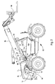
- FIG. 2 shows a mobile telescopic loader 82 with a telescopically extendable arm 86 pivotably articulated on a housing 84 or frame of the telescopic handler 82.
- a hydraulic cylinder 26 for lifting and lowering the arm 86 is arranged between the arm 86 and the housing 84.
- the hydraulic cylinder 26 is pivoted to a first and a second bearing 88, 90, wherein the piston rod side 92 is hinged to the second bearing point 90 on the arm 86 and the piston bottom side 94 at the first bearing 88 on the housing 84.
- the hydraulic tank 20, the pump 18 and the control unit 12 are positioned on or in the housing 84 and connected to each other via hydraulic lines 14, 16, 96. Further the supply lines 22, 24 between control unit 12 and hydraulic cylinder 26 in Fig. 2 can be seen.
- the pipe burst protection device 32 and the switching valve 52 are located in a common valve block directly on the hydraulic cylinder 26.
- the hydraulic accumulator 48 is preferably also disposed directly on the hydraulic cylinder 26, so that between the common valve block and the hydraulic accumulator 48, the hydraulic line 46 can be formed as a rigid connection, which does not require a separate breakaway device. Via a control not shown, control or switching signals are generated with which the control unit 12 and the switching valve 52 (see FIG. 1) are controlled or switched.
- the hydraulic cylinder 26 can be operated such that the boom 86 can be raised, held, lowered or resiliently held.
- activated suspension and in spring position ensures that during excitation, for example, by the chassis of the telehandler 82, shock-like acceleration due to a free swing of the boom 86 are damped, so that there is an increase in ride comfort, especially if with a Work tool 98 loads are absorbed and moved.
- suspension system can be applied to other vehicles, such as wheel loaders or front loaders or to excavators or cranes that hydraulically have actuated components which can be raised or lowered and in which a suspension seems useful.
Landscapes
- Engineering & Computer Science (AREA)
- General Engineering & Computer Science (AREA)
- Mining & Mineral Resources (AREA)
- Civil Engineering (AREA)
- Structural Engineering (AREA)
- Physics & Mathematics (AREA)
- Fluid Mechanics (AREA)
- Mechanical Engineering (AREA)
- Fluid-Pressure Circuits (AREA)
- Vehicle Body Suspensions (AREA)
- Lifting Devices For Agricultural Implements (AREA)
Claims (9)
- Système hydraulique de suspension passive, comportant un vérin hydraulique (26) muni d'une première et d'une deuxième chambre (28, 30), un réservoir hydraulique (20), un moyen de transport (18) pour transporter un liquide hydraulique, une réserve hydraulique (48), une conduite hydraulique (46) montée entre la réserve hydraulique (48) et la première chambre (28), une vanne de commande (52) montée dans la conduite hydraulique (46), une première conduite d'alimentation (22) pour la première chambre (28), une deuxième conduite d'alimentation (24) pour la deuxième chambre (30), un dispositif de protection anti-rupture du tube (32) monté dans la première conduite d'alimentation (22), et un dispositif de commande (12) avec au moins trois positions de commande qui englobent une position de levage, une position d'abaissement et une position neutre pour le vérin hydraulique (26), caractérisé en ce que le dispositif de commande (12) comporte une position de commande supplémentaire, qui constitue une position de suspension, dans laquelle, par l'intermédiaire du dispositif de commande (12), au moins la deuxième conduite d'alimentation (24) peut être reliée au réservoir hydraulique (20) et, en même temps, les liaisons des deux conduites d'alimentation (22, 24) vers le moyen de transport (18) sont interrompues.
- Système hydraulique de suspension passive selon la revendication 1, caractérisé en ce que, dans la position de suspension, le dispositif de commande (12) peut amener la première et la deuxième conduites d'alimentation (22, 24) en liaison avec le réservoir hydraulique (20).
- Système hydraulique de suspension passive selon la revendication 1 ou 2, caractérisé en ce que la vanne de commande (52) comporte une position de fermeture et une position d'ouverture.
- Système hydraulique de suspension passive selon la revendication 3, caractérisé en ce que la vanne de commande (52) dans la position de fermeture ferme dans une direction d'écoulement ou dans les deux directions d'écoulement.
- Système hydraulique de suspension passive selon l'une quelconque des revendications précédentes, caractérisé en ce qu'il est prévu des moyens (64, 66) qui amènent la vanne de commande (52) dans une position de fermeture lorsque le dispositif de commande (12) est dans la position neutre.
- Système hydraulique de suspension passive selon l'une quelconque des revendications précédentes, caractérisé en ce qu'il est prévu des moyens (64, 66) qui amènent la vanne de commande (52) dans une position de fermeture lorsque le dispositif de commande (12) n'est pas dans la position de suspension.
- Système hydraulique de suspension passive selon l'une quelconque des revendications 3 à 5, caractérisé en ce qu'il est prévu un temporisateur qui, lorsque le dispositif de commande (12) est en position neutre, provoque une temporisation préréglable de la commutation de la vanne de commande (52) dans la position de fermeture.
- Système hydraulique de suspension passive selon l'une quelconque des revendications précédentes, caractérisé en ce que le dispositif de commande (12) est une soupape à coulisse, qui comporte pour chaque position de commande au moins deux entrées et deux sorties.
- Système hydraulique de suspension passive selon l'une quelconque des revendications précédentes, caractérisé en ce que le dispositif de protection anti-rupture de tube (32) comporte un clapet anti-retour (36), fermant vers le dispositif de commande (12), et un clapet de décharge (34), le clapet de décharge (34) pouvant être commandé par les pressions qui règnent dans les conduites d'alimentation (22, 24).
Applications Claiming Priority (2)
| Application Number | Priority Date | Filing Date | Title |
|---|---|---|---|
| DE102004012362 | 2004-03-13 | ||
| DE102004012362A DE102004012362A1 (de) | 2004-03-13 | 2004-03-13 | Hydraulische Anordnung |
Publications (2)
| Publication Number | Publication Date |
|---|---|
| EP1574626A1 EP1574626A1 (fr) | 2005-09-14 |
| EP1574626B1 true EP1574626B1 (fr) | 2007-08-08 |
Family
ID=34813688
Family Applications (1)
| Application Number | Title | Priority Date | Filing Date |
|---|---|---|---|
| EP05101766A Not-in-force EP1574626B1 (fr) | 2004-03-13 | 2005-03-08 | Système hydraulique de suspension passive |
Country Status (7)
| Country | Link |
|---|---|
| US (1) | US7140178B2 (fr) |
| EP (1) | EP1574626B1 (fr) |
| AU (1) | AU2005201082B2 (fr) |
| CA (1) | CA2500627C (fr) |
| DE (2) | DE102004012362A1 (fr) |
| ES (1) | ES2289652T3 (fr) |
| NZ (1) | NZ538731A (fr) |
Families Citing this family (18)
| Publication number | Priority date | Publication date | Assignee | Title |
|---|---|---|---|---|
| DE102005038333A1 (de) * | 2005-08-11 | 2007-02-15 | Deere & Company, Moline | Hydraulische Anordnung |
| EP1914353A3 (fr) | 2006-10-19 | 2011-04-20 | Hitachi Construction Machinery Co., Ltd. | Engin de construction |
| US20090025352A1 (en) * | 2007-02-26 | 2009-01-29 | Angelle Clinton J | Apparatus and Method for Handling a Cutting Device |
| AT505111B1 (de) | 2007-04-12 | 2009-05-15 | Rosenbauer Int Ag | Einsatzvorrichtung zur brandbekämpfung |
| FR2923352B1 (fr) * | 2007-11-12 | 2010-01-15 | Signalisation Moderne Autoroutiere Sma | Machine de fauchage/debroussaillage/elagage munie d'un moyen d'amortissement de chocs |
| KR101655458B1 (ko) * | 2009-12-24 | 2016-09-07 | 두산인프라코어 주식회사 | 건설기계의 유압펌프 제어용 밸브 |
| US8176992B2 (en) | 2010-05-28 | 2012-05-15 | Cnh Canada, Ltd. | Electronically controlled hydraulic system for an agricultural implement |
| DE102012106185B3 (de) * | 2012-07-10 | 2013-11-21 | Fsp Fluid Systems Partners Holding Ag | Steueranordnung für ein hydropneumatisches Federungssystem sowie hydropneumatisches Federungssystem mit einer solchen Steueranordnung |
| DE102012021544B4 (de) * | 2012-10-29 | 2014-07-10 | Terex Cranes Germany Gmbh | Teleskopiereinheit mit Zusatzfunktion |
| GB2514112C (en) * | 2013-05-13 | 2016-11-30 | Caterpillar Inc | Valve Arrangement |
| CN104033450B (zh) * | 2014-05-28 | 2016-05-25 | 广西柳工机械股份有限公司 | 液控卸荷阀 |
| CN105275907A (zh) * | 2015-11-25 | 2016-01-27 | 上海电气液压气动有限公司 | 一种支撑油缸阀块装置 |
| JP6723839B2 (ja) * | 2016-06-09 | 2020-07-15 | 株式会社クボタ | 作業機の油圧システム |
| JP7164294B2 (ja) * | 2017-10-24 | 2022-11-01 | 株式会社小松製作所 | 作業車両 |
| CN112384662A (zh) * | 2018-08-30 | 2021-02-19 | 沃尔沃建筑设备公司 | 用于建筑设备的液压回路 |
| CN110541448B (zh) * | 2019-09-12 | 2022-03-01 | 三一重机有限公司 | 挖掘机动臂液控系统和挖掘机 |
| DE202020104190U1 (de) | 2020-07-21 | 2021-10-22 | Liebherr-Werk Nenzing Gmbh | Hydrauliksystem für eine Rückfallstütze und Arbeitsgerät |
| CN117159960A (zh) * | 2023-09-27 | 2023-12-05 | 北京中卓时代消防装备科技有限公司 | 一种消防车的穿刺针的控制方法、控制装置和消防车 |
Family Cites Families (17)
| Publication number | Priority date | Publication date | Assignee | Title |
|---|---|---|---|---|
| US4367673A (en) * | 1981-01-09 | 1983-01-11 | Dresser Industries, Inc. | System and method for controlling the elevation of a boom hoist device |
| US4522109A (en) * | 1983-11-21 | 1985-06-11 | J. I. Case Company | Leak-detecting hydraulic system |
| JPS63265023A (ja) * | 1987-04-20 | 1988-11-01 | Kobe Steel Ltd | 車両系建設機械の振動抑制装置 |
| US5116188A (en) * | 1987-09-16 | 1992-05-26 | Kabushiki Kaisha Kobe Seiko Sho | Vibration suppressing device for wheeled construction equipment |
| WO1990005814A1 (fr) * | 1988-11-23 | 1990-05-31 | A & T Hansson Konsult Ab | Dispositif amortisseur de chocs pour machine mobile |
| DE68918930T2 (de) * | 1989-02-06 | 1995-03-23 | Kobe Steel Ltd | Vorrichtung zur Unterdrückung von Vibrationen für Baumaschinen auf Rädern. |
| WO1993005244A1 (fr) * | 1991-09-04 | 1993-03-18 | O&K Orenstein & Koppel Ag | Systeme hydraulique amortisseur de vibrations pour engins de chantiers munis d'outils |
| DE4221943C2 (de) * | 1991-09-04 | 1996-01-25 | Orenstein & Koppel Ag | Hydraulikanlage für mit Arbeitsgeräten versehene fahrbare Arbeitsmaschinen |
| DE4129509C2 (de) * | 1991-09-05 | 1994-06-16 | Rexroth Mannesmann Gmbh | Hydraulische Steueranordnung für Baumaschinen |
| DE19608758A1 (de) * | 1996-03-07 | 1997-09-11 | Rexroth Mannesmann Gmbh | Hydraulische Ventilanordnung |
| US5992146A (en) * | 1996-04-12 | 1999-11-30 | Caterpillar Inc. | Variable rate ride control system |
| DE19754828C2 (de) * | 1997-12-10 | 1999-10-07 | Mannesmann Rexroth Ag | Hydraulische Steueranordnung für eine mobile Arbeitsmaschine, insbesondere für einen Radlader, zur Dämpfung von Nickschwingungen |
| GB2365407B (en) * | 2000-05-25 | 2003-10-08 | Bamford Excavators Ltd | Hydraulic system for wheeled loader |
| JP2002117539A (ja) * | 2000-10-10 | 2002-04-19 | Tdk Corp | 光記録媒体 |
| US6382326B1 (en) * | 2001-03-20 | 2002-05-07 | Deere & Company | Implement suspension with accumulator |
| DE10133616A1 (de) * | 2001-07-13 | 2003-01-30 | Bosch Rexroth Ag | Hydraulische Steueranordnung |
| DE10227966A1 (de) * | 2002-06-22 | 2004-01-08 | Deere & Company, Moline | Hydraulische Steueranordnung für eine mobile Arbeitsmaschine |
-
2004
- 2004-03-13 DE DE102004012362A patent/DE102004012362A1/de not_active Withdrawn
-
2005
- 2005-03-08 ES ES05101766T patent/ES2289652T3/es active Active
- 2005-03-08 DE DE502005001155T patent/DE502005001155D1/de not_active Expired - Lifetime
- 2005-03-08 EP EP05101766A patent/EP1574626B1/fr not_active Not-in-force
- 2005-03-10 NZ NZ538731A patent/NZ538731A/en not_active IP Right Cessation
- 2005-03-11 US US11/077,645 patent/US7140178B2/en not_active Expired - Lifetime
- 2005-03-11 AU AU2005201082A patent/AU2005201082B2/en not_active Ceased
- 2005-03-11 CA CA002500627A patent/CA2500627C/fr not_active Expired - Fee Related
Also Published As
| Publication number | Publication date |
|---|---|
| AU2005201082B2 (en) | 2010-07-22 |
| EP1574626A1 (fr) | 2005-09-14 |
| NZ538731A (en) | 2006-02-24 |
| CA2500627A1 (fr) | 2005-09-13 |
| DE102004012362A1 (de) | 2005-09-22 |
| AU2005201082A1 (en) | 2005-09-29 |
| US20050198949A1 (en) | 2005-09-15 |
| ES2289652T3 (es) | 2008-02-01 |
| US7140178B2 (en) | 2006-11-28 |
| DE502005001155D1 (de) | 2007-09-20 |
| CA2500627C (fr) | 2008-08-12 |
Similar Documents
| Publication | Publication Date | Title |
|---|---|---|
| EP1574626B1 (fr) | Système hydraulique de suspension passive | |
| EP1752587B1 (fr) | Agencement hydraulique | |
| DE102004056418B4 (de) | Hydraulische Anordnung | |
| DE102004012382B4 (de) | Hydraulische Anordnung | |
| EP1987256B1 (fr) | Dispositif de commande et commande pilote hydraulique | |
| EP1897847B1 (fr) | Appareil de chargement | |
| DE10327132A1 (de) | Hydraulikschaltung für eine Ausleger-Zylinder-Kombination, welche eine Umlauffunktion aufweist | |
| EP1003939B1 (fr) | Dispositif de commande hydraulique destine a une machine de travail mobile, notamment a une chargeuse a roues | |
| EP1743981A1 (fr) | Agencement hydraulique | |
| DE4438899C1 (de) | Energierückgewinnungsvorrichtung | |
| EP1375926A1 (fr) | Dispositif de commande hydraulique pour une machine de travail | |
| DE112014005049T5 (de) | Hydraulikdruckkreis und Arbeitsmaschine | |
| EP4367405B1 (fr) | Dispositif d'actionnement pour au moins un consommateur actionné fluidiquement | |
| DE202008005035U1 (de) | Arbeitsgerät und Notablasssystem | |
| EP2910796B9 (fr) | Assemblage avec un dispositif de vanne de commande à position flottante | |
| DE102022126034A1 (de) | Ventilanordnung für Arbeitsmaschinen mit ölhydraulischem Werkzeug | |
| EP1432878B1 (fr) | Dispositif de commande | |
| DE102017206581A1 (de) | Ventilanordnung für Stiel-Zylinder mit zwei Betriebszuständen | |
| EP3816095A1 (fr) | Machine motrice dotée d'un cadre et d'une flèche pivotante | |
| DE19751357B4 (de) | Hydraulische Steueranordnung für eine mobile Arbeitsmaschine, insbesondere für einen Radlader, zur Dämpfung von Nickschwingungen | |
| EP4711629A1 (fr) | Dispositif de commande d'une soupape de commande hydraulique pour un tracteur agricole | |
| EP1789270B1 (fr) | Systeme de suspension | |
| DE112016006779T5 (de) | Arbeitsfahrzeug und Hydraulik-Steuerungsverfahren | |
| DE102022114096A1 (de) | Mobile hydraulische Baumaschine mit Notstopventilen und Verfahren zur Steuerung einer mobilen hydraulischen Baumaschine |
Legal Events
| Date | Code | Title | Description |
|---|---|---|---|
| PUAI | Public reference made under article 153(3) epc to a published international application that has entered the european phase |
Free format text: ORIGINAL CODE: 0009012 |
|
| AK | Designated contracting states |
Kind code of ref document: A1 Designated state(s): AT BE BG CH CY CZ DE DK EE ES FI FR GB GR HU IE IS IT LI LT LU MC NL PL PT RO SE SI SK TR |
|
| AX | Request for extension of the european patent |
Extension state: AL BA HR LV MK YU |
|
| 17P | Request for examination filed |
Effective date: 20060314 |
|
| AKX | Designation fees paid |
Designated state(s): DE ES FR GB IT |
|
| GRAP | Despatch of communication of intention to grant a patent |
Free format text: ORIGINAL CODE: EPIDOSNIGR1 |
|
| RTI1 | Title (correction) |
Free format text: HYDRAULIC PASSIVE SUSPENSION SYSTEM |
|
| GRAS | Grant fee paid |
Free format text: ORIGINAL CODE: EPIDOSNIGR3 |
|
| GRAA | (expected) grant |
Free format text: ORIGINAL CODE: 0009210 |
|
| AK | Designated contracting states |
Kind code of ref document: B1 Designated state(s): DE ES FR GB IT |
|
| REG | Reference to a national code |
Ref country code: GB Ref legal event code: FG4D Free format text: NOT ENGLISH |
|
| REF | Corresponds to: |
Ref document number: 502005001155 Country of ref document: DE Date of ref document: 20070920 Kind code of ref document: P |
|
| GBT | Gb: translation of ep patent filed (gb section 77(6)(a)/1977) |
Effective date: 20070906 |
|
| ET | Fr: translation filed | ||
| REG | Reference to a national code |
Ref country code: ES Ref legal event code: FG2A Ref document number: 2289652 Country of ref document: ES Kind code of ref document: T3 |
|
| PLBE | No opposition filed within time limit |
Free format text: ORIGINAL CODE: 0009261 |
|
| STAA | Information on the status of an ep patent application or granted ep patent |
Free format text: STATUS: NO OPPOSITION FILED WITHIN TIME LIMIT |
|
| 26N | No opposition filed |
Effective date: 20080509 |
|
| PGFP | Annual fee paid to national office [announced via postgrant information from national office to epo] |
Ref country code: DE Payment date: 20140219 Year of fee payment: 10 |
|
| PGFP | Annual fee paid to national office [announced via postgrant information from national office to epo] |
Ref country code: ES Payment date: 20140326 Year of fee payment: 10 Ref country code: FR Payment date: 20140317 Year of fee payment: 10 Ref country code: IT Payment date: 20140320 Year of fee payment: 10 |
|
| PGFP | Annual fee paid to national office [announced via postgrant information from national office to epo] |
Ref country code: GB Payment date: 20140327 Year of fee payment: 10 |
|
| REG | Reference to a national code |
Ref country code: DE Ref legal event code: R119 Ref document number: 502005001155 Country of ref document: DE |
|
| GBPC | Gb: european patent ceased through non-payment of renewal fee |
Effective date: 20150308 |
|
| PG25 | Lapsed in a contracting state [announced via postgrant information from national office to epo] |
Ref country code: IT Free format text: LAPSE BECAUSE OF NON-PAYMENT OF DUE FEES Effective date: 20150308 |
|
| REG | Reference to a national code |
Ref country code: FR Ref legal event code: ST Effective date: 20151130 |
|
| PG25 | Lapsed in a contracting state [announced via postgrant information from national office to epo] |
Ref country code: GB Free format text: LAPSE BECAUSE OF NON-PAYMENT OF DUE FEES Effective date: 20150308 Ref country code: DE Free format text: LAPSE BECAUSE OF NON-PAYMENT OF DUE FEES Effective date: 20151001 |
|
| PG25 | Lapsed in a contracting state [announced via postgrant information from national office to epo] |
Ref country code: FR Free format text: LAPSE BECAUSE OF NON-PAYMENT OF DUE FEES Effective date: 20150331 |
|
| REG | Reference to a national code |
Ref country code: ES Ref legal event code: FD2A Effective date: 20160602 |
|
| PG25 | Lapsed in a contracting state [announced via postgrant information from national office to epo] |
Ref country code: ES Free format text: LAPSE BECAUSE OF NON-PAYMENT OF DUE FEES Effective date: 20150309 |