EP1574844A1 - Analyse de matérial particulaire - Google Patents
Analyse de matérial particulaire Download PDFInfo
- Publication number
- EP1574844A1 EP1574844A1 EP05250470A EP05250470A EP1574844A1 EP 1574844 A1 EP1574844 A1 EP 1574844A1 EP 05250470 A EP05250470 A EP 05250470A EP 05250470 A EP05250470 A EP 05250470A EP 1574844 A1 EP1574844 A1 EP 1574844A1
- Authority
- EP
- European Patent Office
- Prior art keywords
- housing
- hole
- slide valve
- outlet
- cover
- Prior art date
- Legal status (The legal status is an assumption and is not a legal conclusion. Google has not performed a legal analysis and makes no representation as to the accuracy of the status listed.)
- Withdrawn
Links
Images


Classifications
-
- G—PHYSICS
- G01—MEASURING; TESTING
- G01N—INVESTIGATING OR ANALYSING MATERIALS BY DETERMINING THEIR CHEMICAL OR PHYSICAL PROPERTIES
- G01N21/00—Investigating or analysing materials by the use of optical means, i.e. using sub-millimetre waves, infrared, visible or ultraviolet light
- G01N21/01—Arrangements or apparatus for facilitating the optical investigation
- G01N21/03—Cuvette constructions
- G01N21/05—Flow-through cuvettes
Definitions
- THIS INVENTION relates to the analysis of a material in particulate form.
- the information required for these purposes is obtained by analysing the mineral being processed at various stages of its treatment.
- the proportions of the constituents as the mineral passes through the processing plant can be used as an indication of the efficiency of the plant and enable adjustments to the process to be made to achieve maximum remediation yield.
- the known methods of determining the proportions of the constituents in the minerals undergoing processing can be divided into “human” and "machine".
- the main "human” method involves the preparation of a sample, the proportions of the constituents of which are the same as the proportions in the mineral being processed. Obtaining the sample is a lengthy procedure. The first step is to take a number of kilograms of the granular mineral to ensure that the constituents of the sample are as representative as possible of the constituents of the bulk. The sample is split into small portions and then some of these portions recombined until the procedure has eliminated any remaining difference between the proportions in the sample and the proportions in the mineral being processed. The grains in the sample are then identified and counted by a skilled grain counter using a microscope and an optical grid over which the grains are spread.
- Another "human” method relies on the skill of the person carrying out the test as it is based on the difference between the colour of the sample being checked and the colour of a standard sample. This is not a particularly accurate method as the human eye cannot pick up small changes in contrast or colour.
- machine methods are numerous but these have a number of shortcomings. Some require expensive equipment and, generally, sample preparation is time consuming. Also, some of the equipment is such that it can only be run by trained scientists and even then only in laboratory conditions. Examples of “machine” methods known to the Applicant as at 23 January 2002, as well as a recent development in the spectral analysis of material in particulate form, are described in WO 03/062804.
- the present invention seeks to provide a new analysis method and new analysis apparatus which enable real time information on the composition of a material to be obtained.
- the method and apparatus of the present invention are primarily intended for use in the processing of minerals but can be used in other industries where the composition of a material must be determined.
- a method of analysing a material in particulate form which comprises causing the material to flow as a stream into the open upper end of a housing and out of the lower end of the housing, the housing having a restricted outlet and the rate of flow into the housing exceeding the outflow thereby causing material to back-up from the outlet and fill the housing, directing light into the material which is moving downwardly in the housing from the upper end to the lower end, collecting light reflected from the moving material, and feeding the collected light to a spectrometer.
- apparatus for analysing material in particulate form which comprises a housing having an open upper end and a restricted outlet at the lower end, a transparent cover in one wall of the housing and a probe structure for directing light into the housing through said cover and collecting light reflected from particulate material in the housing.
- the apparatus can further include a means such as a slide valve which enables the rate of flow from the housing to be adjusted.
- Said slide valve can comprise a section with a hole therein, the section being movable with respect to the housing so as to vary the area of the hole which is within the housing.
- the plane in which the inner face of said cover lies can intersect said hole whereby a part of the hole lies inside the housing and a part of the hole lies outside the housing, the part of the hole inside the housing forming said restricted outlet.
- Said slide valve can have a forward position in which the hole registers with the housing thereby to open up said slot and allow any material blocking the housing to drop from the housing.
- Said open upper end of the housing is preferably bounded by surfaces which intersect to form sharp edges which cut the flowing material and split the flow into a portion that enters the housing and a portion which flows around the housing.
- Said sharp edges are bounded between vertical inner surfaces of said housing and further surfaces which are inclined to vertical and which slope downwardly away from said edges.
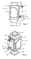
- the apparatus is generally designated 10 and comprises a vertically elongate housing 12 which is attached to the side of a casing 14.
- the upper edge of the housing 12 is chamfered to provide inclined upper surfaces 16 which intersect the internal surfaces 18 of the housing 12 thereby to define sharp edges 20. More specifically, the internal surfaces 18 of the housing 12 are vertical and intersect the surfaces 16 which slope downwardly and outwardly away from their lines of intersection with the surfaces 18.
- the housing 12 has an opening in one side wall thereof, the opening having a transparent cover 22 ( Figures 3 & 4) of wear resistant material fitted into it.
- the lower end of the housing 12 is partially closed by a slide valve 24 ( Figure 5) and the upper end of the housing 12 is open at 26.
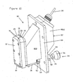
- a probe 28 protrudes from the casing 14 through a probe mounting 29 (see Figures 6 to 8).
- the probe 28 slopes at an angle of between 30 and 60 degrees with respect to the horizontal.
- the probe 28 comprises one or more optical fibres for directing light through the cover 22 and into the housing 12, and one or more further optical fibres for collecting reflected light and feeding it to a spectrometer (not shown).
- the spectrometer is connected to an optical cable (not shown) which is itself connected to the probe 28.
- the probe structure can comprise a first probe for directing light through the cover 22 and a second probe for receiving reflected light.
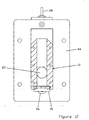
- the slide valve 24 comprises a U-shaped section 30 having a rectangular hole 32 in it.
- the section 30 is integral with a T-shaped section 34.
- a rod 36 forming part of the operating mechanism of the slide valve 24, is secured to the T-shaped section 34 by means of a grub screw 38.
- An elongate slot 40 is provided in the T-shaped section 34 for receiving a bolt 42 (see Figure 2), which screws into a tapped bore in the base plate of the casing 14.
- the front edge of the U-shaped section 30 bounding the hole 32 has a chamfered inner lip 31, as can be seen in Figure 5, to assist in preventing build-up and blockage of material flowing through the hole 32.
- the rod 36 passes through a coil spring 44 and through a sleeve 46.
- the sleeve 46 has a flange 48 at one end and a removable collar 50 at the other end.
- a grub screw 52 releasably secures the flange 48 to the rod 36.
- a further grub screw 54 secures the collar 50 to the sleeve 46.
- a knob 56 is attached to the rod 36 by means of another grub screw 58.
- the slide valve 24 can be adjusted back and forth by means of the rod 36 to which the knob 56 is attached. Movement of the slide valve 24 is as shown by arrow A in Figure 2.
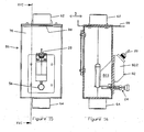
- FIG. 60 the structure illustrated is generally designated 60 and comprises two short pipes 62, 64, two flanges 66, 68 which enable it to be bolted into a pipe line, and walling generally designated 70 which defines an analysis chamber.
- the pipe 62 forms the inlet to the chamber and the pipe 64 the outlet from the chamber.
- the walling 70 includes two removable plates 72 so that conditions within the chamber can be inspected.
- the plates 72 can be transparent.
- the walling 70 further includes a plate 74 by means of which the casing 14 is attached to the remainder of the walling 70.
- the housing 12 is within the analysis chamber, the open upper end 26 of the housing 12 being aligned with the inlet pipe 62 (see Figure 6).
- a downwardly tapering cone 76 ( Figures 7 to 9) forms a passageway between the analysis chamber bounded by the walling 70 and the pipe 64.
- the rod 36 is pushed, from right to left in Figure 7, through a hole in the plate 74.
- the plate 74 is at this time detached from the remainder of the walling 70.
- the sleeve 46 and then the spring 44 are slid onto the rod 36 and the sleeve 46 secured by the grub screw 52.
- the sleeve 46 passes through the hole in the plate 74 and the collar 50 is re-secured to the sleeve 46, on the end thereof which will be inside the chamber, by fastening the grub screw 54.
- the spring 44 pushes the sleeve 46 and rod 36 to the right as viewed in Figure 7 so that the collar 50 abuts the inside face of the plate 74.
- the knob 56 is then secured to the rod 36 by means of the grub screw 58 and the slide valve 24 is secured to the casing 14 by means of the bolt 42 which passes through the elongate slot 40.
- the bolt 42 cooperates with the slot 40 to allow the slide valve 24 to be releasably attached to the casing 14 whilst allowing the slide valve 24 to be slid, back and forth, as indicated by the double-headed arrow A ( Figure 2).
- the plate 74 is then attached to the remainder of the walling 70.
- the U-shaped section 30 of the slide valve 24 is in the lower part of the housing 12.
- the rectangular hole 32 between the U-shaped section 30 and the T-shaped section 34 of the slide valve 24 protrudes just beyond the wall of the housing 12 which has the cover 22 in it.
- the area of the hole 32 which is beyond this wall is thus within the area bounded by the housing 12 and forms a slot through which material that has entered the housing 12 from above can exit from the housing 12.
- Particulate material flowing in through the pipe 62 piles up in the housing 12 and surplus material flows around the housing 12 to the outlet pipe 64.
- the knob 56 is pushed to the right, as viewed in Figure 2. This compresses the spring 44 and moves the slide valve 24 to a position in which the hole 32 is in register with the housing 12. This enables any material blocking the outlet slot to fall out of the bottom of the housing 12.
- the spring 44 pushes on the flange 48 and moves the slide valve 24 back to its operative position in which the collar 50 is against the plate 74.
- the mineral or other material to be spectrographically analysed flows into the upper end of the housing 12 through the opening 26 at a rate which exceeds the rate at which it can flow out of the housing 12 through the slot.
- the housing 12 thus fills up and surplus material simply flows down the outside of the housing 12.
- the apparatus 80 includes a casing 82, which comprises two sections 82.1, 82.2 separated by a vertically elongate plate 84.
- the vertical elongate housing 12 is attached to the section 82.1.
- the assembly and operation of the slide valve 24 within the apparatus 80 is the same as is described above in respect of apparatus 10.
- the structure 86 includes an L-shaped shut-off and control valve 88 which can be slid, as shown by the double-headed arrow B in Figure 16, to adjust flow of the material to be analysed across the cover 22.
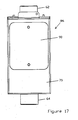
- a removable plate 90 ( Figures 16 & 17), analogous to the two plates 72 of the structure 60, is attached to the walling 70 so that conditions within the analysis chamber can be inspected.
- the plate 90 can be transparent.
- the assembly and operation of the structure 86 is as described above in relation to the structure 60.
- the apparatus 10, structure 60, apparatus 80 and structure 60 have been illustrated and described in the vertical orientation, but may be slightly inclined to the vertical.
- the material in particulate form to be analysed by the structures 60 and 86 can be in the form of a dry powder or can be suspended in a liquid so as to form a slurry.
Landscapes
- Physics & Mathematics (AREA)
- Health & Medical Sciences (AREA)
- Life Sciences & Earth Sciences (AREA)
- Chemical & Material Sciences (AREA)
- Analytical Chemistry (AREA)
- Biochemistry (AREA)
- General Health & Medical Sciences (AREA)
- General Physics & Mathematics (AREA)
- Immunology (AREA)
- Pathology (AREA)
- Investigating Or Analysing Materials By Optical Means (AREA)
- Optical Measuring Cells (AREA)
- Sampling And Sample Adjustment (AREA)
Applications Claiming Priority (2)
| Application Number | Priority Date | Filing Date | Title |
|---|---|---|---|
| ZA200401962 | 2004-03-11 | ||
| ZA200401962 | 2004-03-11 |
Publications (1)
| Publication Number | Publication Date |
|---|---|
| EP1574844A1 true EP1574844A1 (fr) | 2005-09-14 |
Family
ID=34827824
Family Applications (1)
| Application Number | Title | Priority Date | Filing Date |
|---|---|---|---|
| EP05250470A Withdrawn EP1574844A1 (fr) | 2004-03-11 | 2005-01-28 | Analyse de matérial particulaire |
Country Status (12)
| Country | Link |
|---|---|
| US (1) | US7483132B2 (fr) |
| EP (1) | EP1574844A1 (fr) |
| CN (1) | CN100472202C (fr) |
| AU (1) | AU2005200357B2 (fr) |
| BR (1) | BRPI0500545A (fr) |
| CA (1) | CA2493652C (fr) |
| MX (1) | MXJL05000007A (fr) |
| NO (1) | NO20050311L (fr) |
| PE (1) | PE20060133A1 (fr) |
| RU (1) | RU2298172C2 (fr) |
| UA (1) | UA83004C2 (fr) |
| ZA (1) | ZA200500641B (fr) |
Families Citing this family (1)
| Publication number | Priority date | Publication date | Assignee | Title |
|---|---|---|---|---|
| CN116046623B (zh) * | 2023-03-31 | 2023-06-06 | 山东正润环境检测技术服务有限公司 | 一种用于工厂厂房的空气灰尘检测装置 |
Citations (6)
| Publication number | Priority date | Publication date | Assignee | Title |
|---|---|---|---|---|
| US3478597A (en) * | 1967-02-15 | 1969-11-18 | Fmc Corp | Particle size monitor |
| US3918471A (en) | 1973-05-23 | 1975-11-11 | Shire Bernard S | Gate valve device |
| DE2853459A1 (de) * | 1978-10-04 | 1980-04-10 | Buehler Ag Geb | Verfahren und vorrichtung zur kontrolle einer mehlcharge |
| US6327899B1 (en) * | 1997-10-09 | 2001-12-11 | Claas Selbstfahrende Erntemaschinen Gmbh | Device for moisture measurement in harvesting machines |
| US6357305B1 (en) | 1997-05-20 | 2002-03-19 | Sympatec Gmbh | Method and device for sampling dispersed streams of material |
| US20040012781A1 (en) | 2002-04-04 | 2004-01-22 | Lane Gehrlein | Method and apparatus for determining the homogeneity of a granulation during tableting |
Family Cites Families (22)
| Publication number | Priority date | Publication date | Assignee | Title |
|---|---|---|---|---|
| US4125769A (en) * | 1977-05-18 | 1978-11-14 | Gesellschaft Fur Kernenergieverwertung In Schiffbau Und Schiffahrt Mbh | Apparatus for quantitative in-line X-ray fluorescence analysis of slurries |
| US4450576A (en) * | 1979-04-20 | 1984-05-22 | Gesellschaft mit Kernforschungszentrum Karlsruhe beschrankter Haftung | Apparatus for continuously measuring the element content in slurries |
| US4814711A (en) * | 1984-04-05 | 1989-03-21 | Deseret Research, Inc. | Survey system and method for real time collection and processing of geophysicals data using signals from a global positioning satellite network |
| US4686474A (en) * | 1984-04-05 | 1987-08-11 | Deseret Research, Inc. | Survey system for collection and real time processing of geophysical data |
| DE3509671C2 (de) | 1985-03-18 | 1987-04-09 | Reinhard 5461 Windhagen Wirtgen | Sensoranordnung für die Steuerung der Frästiefeneinstellung eines Oberflächenfräsers |
| DD244821A1 (de) | 1985-12-27 | 1987-04-15 | Deuben Braunkohlenwerk | Verfahren zur steuerung von baggern und transporteinrichtungen |
| US5385827A (en) * | 1989-09-20 | 1995-01-31 | Clark; John R. | Method of geochemical prospecting |
| US5065019A (en) | 1990-05-07 | 1991-11-12 | Southwest Research Institute | Method for determining petroleum saturation in a subsurface |
| US5157976A (en) | 1990-07-27 | 1992-10-27 | Hajime Industries Ltd. | Powder granule sample inspection apparatus |
| US5133901A (en) * | 1991-03-01 | 1992-07-28 | Westinghouse Electric Corp. | System and method for on-line monitoring and control of heavy metal contamination in soil washing process |
| US5416577A (en) | 1993-07-02 | 1995-05-16 | Honeywell Inc. | Color sensor for optically measuring consisting and brightness of materials |
| DE4414622A1 (de) | 1994-04-18 | 1995-10-19 | Marcus Dipl Ing Gutzmer | Verfahren und Vorrichtung zur Bestimmung von Fremdstoffen in körnigen Medien |
| US5461229A (en) | 1994-06-06 | 1995-10-24 | Unisys Corporation | On-the-go optical spectroscopy soil analyzer |
| US5926262A (en) * | 1997-07-01 | 1999-07-20 | Lj Laboratories, L.L.C. | Apparatus and method for measuring optical characteristics of an object |
| US6100526A (en) | 1996-12-30 | 2000-08-08 | Dsquared Development, Inc. | Grain quality monitor |
| US6836325B2 (en) * | 1999-07-16 | 2004-12-28 | Textron Systems Corporation | Optical probes and methods for spectral analysis |
| US6770249B1 (en) * | 1999-09-27 | 2004-08-03 | Chester W. Whitman | Process to selectively recover metals from waste dusts, sludges and ores |
| US6418805B1 (en) | 1999-11-18 | 2002-07-16 | Textron Systems Corporation | Constituent sensing system |
| EP1264170B1 (fr) | 2000-03-10 | 2009-02-04 | Textron Systems Corporation | Sondes optiques et procedes d'analyse spectrale |
| SE0100283D0 (sv) * | 2001-01-31 | 2001-01-31 | Astrazeneca Ab | Sampling apparatus |
| GB2379976B (en) * | 2001-09-20 | 2005-02-02 | Ndc Infrared Eng Ltd | Optical sampling window |
| US7113265B1 (en) * | 2003-05-20 | 2006-09-26 | The United States Of America As Represented By The Administrator Of The National Aeronautics And Space Administration | Powder handling device for analytical instruments |
-
2005
- 2005-01-19 CA CA002493652A patent/CA2493652C/fr not_active Expired - Lifetime
- 2005-01-20 NO NO20050311A patent/NO20050311L/no not_active Application Discontinuation
- 2005-01-24 ZA ZA2005/00641A patent/ZA200500641B/en unknown
- 2005-01-25 RU RU2005101734/28A patent/RU2298172C2/ru active
- 2005-01-28 EP EP05250470A patent/EP1574844A1/fr not_active Withdrawn
- 2005-01-31 AU AU2005200357A patent/AU2005200357B2/en not_active Expired
- 2005-02-01 CN CNB2005100091923A patent/CN100472202C/zh not_active Expired - Lifetime
- 2005-02-23 BR BRPI0500545-0A patent/BRPI0500545A/pt not_active Application Discontinuation
- 2005-03-02 MX MXJL05000007A patent/MXJL05000007A/es active IP Right Grant
- 2005-03-04 US US11/071,462 patent/US7483132B2/en active Active
- 2005-03-08 PE PE2005000264A patent/PE20060133A1/es not_active Application Discontinuation
- 2005-03-10 UA UAA200502199A patent/UA83004C2/ru unknown
Patent Citations (6)
| Publication number | Priority date | Publication date | Assignee | Title |
|---|---|---|---|---|
| US3478597A (en) * | 1967-02-15 | 1969-11-18 | Fmc Corp | Particle size monitor |
| US3918471A (en) | 1973-05-23 | 1975-11-11 | Shire Bernard S | Gate valve device |
| DE2853459A1 (de) * | 1978-10-04 | 1980-04-10 | Buehler Ag Geb | Verfahren und vorrichtung zur kontrolle einer mehlcharge |
| US6357305B1 (en) | 1997-05-20 | 2002-03-19 | Sympatec Gmbh | Method and device for sampling dispersed streams of material |
| US6327899B1 (en) * | 1997-10-09 | 2001-12-11 | Claas Selbstfahrende Erntemaschinen Gmbh | Device for moisture measurement in harvesting machines |
| US20040012781A1 (en) | 2002-04-04 | 2004-01-22 | Lane Gehrlein | Method and apparatus for determining the homogeneity of a granulation during tableting |
Also Published As
| Publication number | Publication date |
|---|---|
| BRPI0500545A (pt) | 2006-04-25 |
| CN1667397A (zh) | 2005-09-14 |
| AU2005200357A1 (en) | 2005-09-29 |
| UA83004C2 (ru) | 2008-06-10 |
| NO20050311D0 (no) | 2005-01-20 |
| US20050260763A1 (en) | 2005-11-24 |
| US7483132B2 (en) | 2009-01-27 |
| CA2493652C (fr) | 2009-11-24 |
| CA2493652A1 (fr) | 2005-09-11 |
| CN100472202C (zh) | 2009-03-25 |
| RU2005101734A (ru) | 2006-07-10 |
| ZA200500641B (en) | 2005-09-28 |
| NO20050311L (no) | 2005-09-12 |
| RU2298172C2 (ru) | 2007-04-27 |
| MXJL05000007A (es) | 2005-09-14 |
| PE20060133A1 (es) | 2006-02-23 |
| AU2005200357B2 (en) | 2006-09-14 |
Similar Documents
| Publication | Publication Date | Title |
|---|---|---|
| US6178383B1 (en) | On-line sampling and image analyzer for determining solid content in a fluid media | |
| US5143224A (en) | Method and apparatus for separating diamonds from associated gangue | |
| CN101532967B (zh) | 一种煤炭旁路在线灰分检测装置和方法 | |
| US10799916B2 (en) | Systems and methods for sorting and collecting enhanced grade metal-bearing ores from metal bearing ores | |
| CN104316450A (zh) | 用于确定颗粒尺寸的装置 | |
| Holmes | Correct sampling and measurement—the foundation of accurate metallurgical accounting | |
| CA2493652C (fr) | Analyse d'un materiau a l'etat particulaire | |
| AU2016224125B2 (en) | An apparatus for taking samples from a slurry flow | |
| CN206208620U (zh) | 一种联合制样机 | |
| Holmes | Sampling mineral commodities-the good, the bad, and the ugly | |
| CN101529222B (zh) | 准备分析试样的方法和设备 | |
| US20240009711A1 (en) | Systems and methods for sorting and collecting enhanced metal-bearing ores of a desired size from metal-bearing ores | |
| CA2009544C (fr) | Methode et dispositif d'echantillonnage a partir d'un transporteur a courroie, en mouvement | |
| Bartlett | Design of primary samplers for slurries in concentrators and statstical methods for measuring components of variance in sampling | |
| CN1328571C (zh) | 基于三维图像分析计算传输流量的装置和方法 | |
| Hinde et al. | Real-time particle size analysis in wet closed-circuit milling | |
| Spangenberg et al. | An overview of sampling best practice in African mining | |
| Naicker et al. | Particle segregation associated with sub-sampling of flotation feed at a UG2 concentrator | |
| BR102013010191A2 (pt) | método e aparelho de análise de material em forma de pequenas partículas | |
| CN100401037C (zh) | 从生产流体中取出浆样品的方法和装置 | |
| Cirulis et al. | Innovative Technology Provides for Real-Time, On-Line Direct Measurement of Particle Size in Individual Cyclones | |
| Dunn et al. | Development of a video-based coal slurry ash analyzer | |
| Holmes | Sampling procedures | |
| Pryor | Sampling and Controls | |
| HOLMES | Keynote Address: Sampling mineral commodities—the good, the bad and the ugly |
Legal Events
| Date | Code | Title | Description |
|---|---|---|---|
| PUAI | Public reference made under article 153(3) epc to a published international application that has entered the european phase |
Free format text: ORIGINAL CODE: 0009012 |
|
| AK | Designated contracting states |
Kind code of ref document: A1 Designated state(s): AT BE BG CH CY CZ DE DK EE ES FI FR GB GR HU IE IS IT LI LT LU MC NL PL PT RO SE SI SK TR |
|
| AX | Request for extension of the european patent |
Extension state: AL BA HR LV MK YU |
|
| 17P | Request for examination filed |
Effective date: 20060314 |
|
| AKX | Designation fees paid |
Designated state(s): AT BE BG CH CY CZ DE DK EE ES FI FR GB GR HU IE IS IT LI LT LU MC NL PL PT RO SE SI SK TR |
|
| 17Q | First examination report despatched |
Effective date: 20120430 |
|
| STAA | Information on the status of an ep patent application or granted ep patent |
Free format text: STATUS: THE APPLICATION IS DEEMED TO BE WITHDRAWN |
|
| 18D | Application deemed to be withdrawn |
Effective date: 20180829 |
|
| RIC1 | Information provided on ipc code assigned before grant |
Ipc: G01N 21/85 20060101AFI20050629BHEP Ipc: G01N 21/05 20060101ALI20050629BHEP Ipc: G01N 1/20 20060101ALI20050629BHEP |