EP1575708B1 - Machine pour fragmenter des matieres de tous types, par ex. des dechets ou du bois - Google Patents
Machine pour fragmenter des matieres de tous types, par ex. des dechets ou du bois Download PDFInfo
- Publication number
- EP1575708B1 EP1575708B1 EP03775058A EP03775058A EP1575708B1 EP 1575708 B1 EP1575708 B1 EP 1575708B1 EP 03775058 A EP03775058 A EP 03775058A EP 03775058 A EP03775058 A EP 03775058A EP 1575708 B1 EP1575708 B1 EP 1575708B1
- Authority
- EP
- European Patent Office
- Prior art keywords
- cutting
- tools
- comminution
- shaft
- rigid
- Prior art date
- Legal status (The legal status is an assumption and is not a legal conclusion. Google has not performed a legal analysis and makes no representation as to the accuracy of the status listed.)
- Expired - Lifetime
Links
- 239000000463 material Substances 0.000 title claims abstract description 63
- 239000002023 wood Substances 0.000 title claims description 7
- 239000002699 waste material Substances 0.000 title claims description 5
- 238000005520 cutting process Methods 0.000 claims abstract description 122
- 238000000034 method Methods 0.000 claims abstract description 14
- 230000008569 process Effects 0.000 claims abstract description 14
- 230000000694 effects Effects 0.000 claims abstract description 9
- 239000010782 bulky waste Substances 0.000 claims description 6
- 230000009471 action Effects 0.000 claims description 5
- 239000010791 domestic waste Substances 0.000 claims description 4
- 239000010815 organic waste Substances 0.000 claims description 3
- 229910000831 Steel Inorganic materials 0.000 claims 2
- 239000010959 steel Substances 0.000 claims 2
- WYTGDNHDOZPMIW-RCBQFDQVSA-N alstonine Natural products C1=CC2=C3C=CC=CC3=NC2=C2N1C[C@H]1[C@H](C)OC=C(C(=O)OC)[C@H]1C2 WYTGDNHDOZPMIW-RCBQFDQVSA-N 0.000 claims 1
- 239000010813 municipal solid waste Substances 0.000 claims 1
- 238000010008 shearing Methods 0.000 claims 1
- 206010041953 Staring Diseases 0.000 description 11
- 241001295925 Gegenes Species 0.000 description 5
- 238000007789 sealing Methods 0.000 description 5
- 238000005265 energy consumption Methods 0.000 description 4
- 230000005540 biological transmission Effects 0.000 description 2
- 230000000875 corresponding effect Effects 0.000 description 2
- 230000002349 favourable effect Effects 0.000 description 2
- 230000003993 interaction Effects 0.000 description 2
- 238000012423 maintenance Methods 0.000 description 2
- 238000004519 manufacturing process Methods 0.000 description 2
- 230000008439 repair process Effects 0.000 description 2
- 238000003860 storage Methods 0.000 description 2
- 230000000712 assembly Effects 0.000 description 1
- 238000000429 assembly Methods 0.000 description 1
- 230000004927 fusion Effects 0.000 description 1
- 230000001976 improved effect Effects 0.000 description 1
- 230000006872 improvement Effects 0.000 description 1
- 239000002655 kraft paper Substances 0.000 description 1
- 230000004048 modification Effects 0.000 description 1
- 238000012986 modification Methods 0.000 description 1
- 239000004033 plastic Substances 0.000 description 1
- 239000002985 plastic film Substances 0.000 description 1
- 229920006255 plastic film Polymers 0.000 description 1
- 230000009467 reduction Effects 0.000 description 1
- 210000002023 somite Anatomy 0.000 description 1
- 230000003319 supportive effect Effects 0.000 description 1
Images
Classifications
-
- B—PERFORMING OPERATIONS; TRANSPORTING
- B02—CRUSHING, PULVERISING, OR DISINTEGRATING; PREPARATORY TREATMENT OF GRAIN FOR MILLING
- B02C—CRUSHING, PULVERISING, OR DISINTEGRATING IN GENERAL; MILLING GRAIN
- B02C18/00—Disintegrating by knives or other cutting or tearing members which chop material into fragments
- B02C18/06—Disintegrating by knives or other cutting or tearing members which chop material into fragments with rotating knives
- B02C18/16—Details
- B02C18/18—Knives; Mountings thereof
- B02C18/182—Disc-shaped knives
-
- B—PERFORMING OPERATIONS; TRANSPORTING
- B02—CRUSHING, PULVERISING, OR DISINTEGRATING; PREPARATORY TREATMENT OF GRAIN FOR MILLING
- B02C—CRUSHING, PULVERISING, OR DISINTEGRATING IN GENERAL; MILLING GRAIN
- B02C18/00—Disintegrating by knives or other cutting or tearing members which chop material into fragments
- B02C18/06—Disintegrating by knives or other cutting or tearing members which chop material into fragments with rotating knives
- B02C18/14—Disintegrating by knives or other cutting or tearing members which chop material into fragments with rotating knives within horizontal containers
- B02C18/142—Disintegrating by knives or other cutting or tearing members which chop material into fragments with rotating knives within horizontal containers with two or more inter-engaging rotatable cutter assemblies
-
- B—PERFORMING OPERATIONS; TRANSPORTING
- B02—CRUSHING, PULVERISING, OR DISINTEGRATING; PREPARATORY TREATMENT OF GRAIN FOR MILLING
- B02C—CRUSHING, PULVERISING, OR DISINTEGRATING IN GENERAL; MILLING GRAIN
- B02C18/00—Disintegrating by knives or other cutting or tearing members which chop material into fragments
- B02C18/06—Disintegrating by knives or other cutting or tearing members which chop material into fragments with rotating knives
- B02C18/16—Details
- B02C18/18—Knives; Mountings thereof
- B02C2018/188—Stationary counter-knives; Mountings thereof
Definitions
- the invention relates to a crushing machine for material of any kind, for. B. waste, such as household waste and bulky waste or wood, comprising a housing provided in a receptacle for the material, at least one driven shaft, are provided on the crushing tools and arranged in the housing rigid cutting tools as counter tools for crushing tools for crushing the material with the in the preamble of claim 1 specified features.
- waste such as household waste and bulky waste or wood
- the comminution tools are known to consist of U-shaped knives lying in a plane perpendicular to the axis of rotation of the shafts and uniformly along and around two substantially parallel and horizontal shafts driven by a motor which can drive the shafts in opposite directions and which have a mutual distance which is slightly greater than twice the distance between the radial outside point of a blade and the axis of rotation.
- the drive devices are provided between the motor and the shafts.
- the material is fed to the knives through a shaft arranged above the knives.
- These knives cooperate with knives fixedly mounted between the shafts on a portion of the frame of the material shredding device as the shafts rotate in opposite directions, thereby moving the cut edge of the sheets at the top of the fixed knives towards each other.
- the mutual distance between the two waves a fixed distance.
- the drive means also comprise, as previously known, a suitable transmission for each of the two shafts, a hydraulic motor with adjustable rotational speeds for operating each shaft, an adjustable pump for supplying each hydraulic motor and transmission through which the motor operates the pumps, which transmits the flow reversing the hydraulic motors to rotate each shaft individually forward and backward in accordance with a predetermined sequence.
- each knife comprises two successively arranged and substantially U-shaped blades, that the radially outer and front parts of the two leaves, seen in the direction of rotation of the cutting movement of the knife are constructed as substantially tangentially oriented wedges, that the distance between the axis of rotation and the wedge of the front blade is shorter than the distance between the axis of rotation and the wedge of the succeeding blade and that the radially outer contour of the succeeding blade substantially a segment of a spiral line around the axis of rotation corresponds.
- the fixed knives are formed by a prior art cutting table fixed to the bottom of a funnel with at least one set; arranged parallel lower knife, which are separated from each other by openings through the table.
- At least one rotatable shaft of a drive unit is provided, which shaft is arranged above the cutting table in a direction which extends perpendicular to the lower blades.
- each knife being provided with a number of teeth and extending partially downwardly into each of its openings in the table.
- Each opening is wider than the associated upper knife, which is also located near one of the lower knives in the associated opening.
- the lower knives extend in a direction intersecting the axis of the shaft or a region around it, it being assumed for this embodiment that according to DK 169 378 a cutting table is already known whose plane already extends below the shaft.
- a set of several blades is arranged on each side of the shaft, the arrangement of which form a V or an inverted V to each other.
- the respective cutting edges may be curved or wave-shaped.
- the crushing tools are offset in the axial direction on the shaft to each other or arranged at a different radial distance, and accordingly the teeth are arranged on the rigid cutting tools, which cutters run as a so-called slab.
- the shaft has discs on which the comminution tools are arranged or formed. These crushing tools work, meshing with the teeth between the spaced-apart rigid cutting tools of the slab.
- the shaft cheap and dismantle, it has on both sides pins, which are detachably connected to the shaft and possibly form a storage area.
- the connection can be designed so that it takes place by means of flanges.
- the housing is made double-walled on the end faces, and between them is a labyrinthine sealing against material outlet provided with a shaft plate provided, which may be conveniently formed by the flanges.
- the cutting contours of the serrated teeth of the rigid cutting tools can be formed by wear elements z. B. are interchangeable.
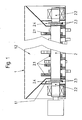
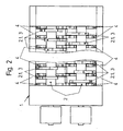
- a shredder according to the invention for household waste, bulky waste or wood consists of a housing 1 with two shafts 2 driven in opposite directions.
- Discs 2.1 are arranged on the shafts 2 and have comminuting tools 3.
- These comminution tools are arranged at a distance from each other on the shafts 2 in such a way that, in cooperation with rigid cutting tools 4, which run in the axial direction of the shafts 2 as a slab, they operate in a parallel offset and crush a material 5 fed in via a receptacle 1.2 in a cutting manner.
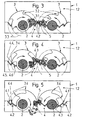
- the comminuting tools 3 have, in each case a direction of rotation of the shafts 2 and in their cross section, two cutting areas 3.1, 3.2, which are designed such that the stability of the comminution tools 3 is not jeopardized.
- An inner cutting area 3.1 detects more material to be comminuted 5 and acts with a relatively small lever arm and an outer cutting area 3.2 detects less material to be shredded 5 and acts with a relatively large lever arm.
- the contours 3.3 of said cutting areas 3.1, 3.2 in the direction of the axes of the shafts 2 each describe a concentric arc around the shafts 2.
- the rigid cutting tools 4 have a plurality of saw-toothed teeth 4.2.
- two mutually perpendicular tooth flanks 4.3 of the teeth 4.2 cooperate with at least one of the cutting areas 3.1, 3.2 in such a way that the respective material 5 is always clamped and notched and cut in its entirety by the available edges of the cutting edges.
- the comminution tools 3 are arranged radially offset relative to one another on the shafts 2 in the axial direction. Not shown in the figures, the possibility that the crushing tools 3 in a different angular position on the shaft 2, ie axially in the cutting profile, z. B. tapered, are arranged. Accordingly, the teeth 4.2 of the axially extending as a slab rigid cutting tools 4 are to be arranged.
- the housing 1 is designed according to Figure 1 at the end faces with a double wall 1.1, in which the pins 2.2 or ends of the shaft 2 have a sealing disc 2.4, which forms a sealing labyrinth with the double wall 1.1.
- the sealing disc 2.4 is formed by the flanges 2.3.
- a crushing machine according to the invention can optimally meet the increased requirements for the comminution of material of the described types, to which means are provided, which detects the gradient of a parameter of the comminution machine and as a reference variable for the control of the comminution machine is used.
Landscapes
- Engineering & Computer Science (AREA)
- Food Science & Technology (AREA)
- Crushing And Pulverization Processes (AREA)
- Debarking, Splitting, And Disintegration Of Timber (AREA)
- Disintegrating Or Milling (AREA)
- Finish Polishing, Edge Sharpening, And Grinding By Specific Grinding Devices (AREA)
- Polysaccharides And Polysaccharide Derivatives (AREA)
- Shovels (AREA)
Claims (12)
- Broyeur pour matière de tout type, par exemple déchets, comme les déchets ménagers, les déchets encombrants ou le bois, notamment les déchets organiques ou les objets encombrants comme les réfrigérateurs, les pneus, les meubles, les tapis, les matelas, les troncs d'arbres, les chutes de bois ou matières similaires, comprenant- un support prévu dans une enceinte (1) pour la matière (5),- au moins un arbre (2) s'appuyant dans l'enceinte (1) et pouvant être entraîné dans les deux sens, sur lequel sont disposés des outils de broyage (3),- des outils de coupe rigides (4) installés dans l'enceinte, dont les arêtes coupantes (4.1) ne coupent pas dans leur prolongement l'axe de l'arbre ou une zone autour de l'axe, contre lesquels outils de coupe rigides (4) les outils de broyage de l'arbre (2) broient la matière intégrée (5),la matière (5) étant, dans une action conjointe des outils de broyage (3) de l'arbre (2), saisie, convoyée et broyée de manière fixe contre les outils de coupe rigide (4) à l'aide de forces spécifiquement faibles,
caractérisé en ce quea) les outils de broyage (3) présentent, vus respectivement dans un sens de rotation de l'arbre (2) et dans sa section transversale, au moins deux zones de coupe (3.1, 3.2) dont au moins une zone de coupe intérieure (3.1) peut saisir et broyer plus de matière à broyer (5) et possède pour ce faire un bras de levier relativement petit ainsi qu'au moins une zone de coupe extérieure (3.2) peut saisir et broyer moins de matière à broyer (5) et possède pour ce faire un bras de levier relativement grand, alors que les contours (3.3) des deux zones de coupe (3.1, 3.2) forment, en direction de l'axe de l'arbre (2), un arc de cercle autour de l'axe de l'arbre (2),b) les outils de coupe rigides (4) présentent plusieurs dents (4.2) disposées en forme de scie et qu'ainsi deux flancs de dents (4.3) des dents (4.2) formant un angle entre eux coopèrent pour la coupe avec une des zones de coupe (3.1, 3.2),c) au début de chaque position de coupe active, une première pointe formant une première découpe transversale (3.4) des outils de broyage (3) est décalée parallèlement par rapport à une pointe formant une deuxième découpe transversale (4.4) d'une dent (4.2) des outils de coupe rigides (4) et orientée de manière à couper au passage, ce qui a pour effet que les forces de coupe générées près de celles agissant entre les zones de coupe (3.1, 3.2) des outils de broyage (3) et les arêtes coupantes (4.1) des outils de coupe rigides (4) ont une arête de cassure supplémentaire et orientée parallèlement à l'axe de l'arbre (2) avec un effet d'entaillage décalé parallèlement sur la matière (5) et une force agissant niveau spécifiquement fort etd) la matière (5), avec une participation agressive des dents (4.2) des outils de coupe fixes (4), subit un processus de broyage actif supplémentaire. - Broyeur selon la revendication 1, caractérisé en ce que les outils de broyage (3) sont décalés les uns par rapport aux autres dans le sens axial sur l'arbre (2) dans leur position angulaire.
- Broyeur selon la revendication 1 ou 2, caractérisé en ce que les outils de broyage (3) sont disposés à distance radiale différente par rapport à l'axe de l'arbre (2).
- Broyeur selon une des revendications 1 à 3, caractérisé en ce que les dents (4.2) des outils de broyage rigides (4) s'étendent sous forme de brames avec un décalage parallèle dans le sens axial et qu'à chaque début de position de coupe (4.5), respectivement au moins une des premières découpes transversales (3.4) est orientée de manière à couper avec un décalage parallèle par rapport à respectivement au moins une des deuxièmes découpes transversales (4.4).
- Broyeur selon une des revendications 1 à 4, caractérisé en ce que l'arbre (2) présente des disques (2.1) sur lesquels sont disposés ou réalisés les outils de broyage (3) qui ont un effet d'empeignage entre les outils de coupe rigides (4) s'étendant à distance sur le brame et de coupe contre ceux-ci.
- Broyeur selon une des revendications 1 à 5, caractérisé en ce que l'arbre (2) présente des tourillons (2.2) qui sont reliés de manière détachable à l'arbre (2).
- Broyeur selon une des revendications 1 à 6, caractérisé en ce que les tourillons (2.2) forment une zone d'appui.
- Broyeur selon une des revendications 1 à 7, caractérisé en ce que la connexion entre le tourillon (2.2) et l'arbre (2) est assurée au moyen de brides (2.3).
- Broyeur selon une des revendications 1 à 8, caractérisé en ce que l'enceinte (1) est réalisée sur ses faces frontales sous forme d'une double paroi (1.1) dans l'intervalle duquel une rondelle d'étanchéité (2.4) reliée à l'arbre (2) est prévue et qu'ainsi une sorte de joint labyrinthe est constitué.
- Broyeur selon une des revendications 1 à 9, caractérisé en ce que la rondelle d'étanchéité (2.4) est constituée par les brides (2.3).
- Broyeur selon une des revendications 1 à 10, caractérisé en ce que les contours de découpe (4.5) des outils de coupe rigides (4) sont renforcés par des éléments d'usure (4.6).
- Broyeur selon une des revendications 1 à 11, caractérisé en ce que sont prévus des moyens d'optimisation du processus de broyage, qui permettent de détecter le gradient d'un paramètre du processus de broyage ou du broyeur et de l'utiliser comme grandeur de guidage pour un contrôle du broyeur.
Applications Claiming Priority (3)
| Application Number | Priority Date | Filing Date | Title |
|---|---|---|---|
| DE10247281 | 2002-10-10 | ||
| DE10247281A DE10247281B3 (de) | 2002-10-10 | 2002-10-10 | Zerkleinerungsmaschine für Material beliebiger Art, z.B. Abfall oder Holz |
| PCT/DE2003/003375 WO2004035215A1 (fr) | 2002-10-10 | 2003-10-09 | Machine pour fragmenter des matieres de tous types, par ex. des dechets ou du bois |
Publications (2)
| Publication Number | Publication Date |
|---|---|
| EP1575708A1 EP1575708A1 (fr) | 2005-09-21 |
| EP1575708B1 true EP1575708B1 (fr) | 2007-02-28 |
Family
ID=31197627
Family Applications (1)
| Application Number | Title | Priority Date | Filing Date |
|---|---|---|---|
| EP03775058A Expired - Lifetime EP1575708B1 (fr) | 2002-10-10 | 2003-10-09 | Machine pour fragmenter des matieres de tous types, par ex. des dechets ou du bois |
Country Status (12)
| Country | Link |
|---|---|
| US (1) | US7237739B2 (fr) |
| EP (1) | EP1575708B1 (fr) |
| JP (1) | JP4213120B2 (fr) |
| AT (1) | ATE355130T1 (fr) |
| AU (1) | AU2003283187A1 (fr) |
| CA (1) | CA2501376C (fr) |
| DE (2) | DE10247281B3 (fr) |
| DK (1) | DK1575708T3 (fr) |
| ES (1) | ES2283839T3 (fr) |
| GB (1) | GB2410908A (fr) |
| NO (1) | NO330393B1 (fr) |
| WO (1) | WO2004035215A1 (fr) |
Cited By (1)
| Publication number | Priority date | Publication date | Assignee | Title |
|---|---|---|---|---|
| DE102008052490A1 (de) | 2008-10-21 | 2010-04-22 | Metso Lindemann Gmbh | Anordnung zur axialen Abstützung einer Welle einer Arbeitsmaschine |
Families Citing this family (10)
| Publication number | Priority date | Publication date | Assignee | Title |
|---|---|---|---|---|
| DK176582B1 (da) | 2005-06-22 | 2008-10-06 | M & J Ind As | Findelingsmaskine |
| IS2409B (is) * | 2005-11-11 | 2008-10-15 | Örn Jensson Guðmundur | Búnaður til þess að skera niður |
| DE202010005584U1 (de) * | 2010-06-08 | 2011-11-03 | Amni Maschinenbau Gmbh | Zerkleinerungsmaschine |
| DE102011001925A1 (de) * | 2011-04-08 | 2012-10-11 | Wincor Nixdorf International Gmbh | Vorrichtung zum Kompaktieren von Behältnissen |
| DE102011119615B4 (de) * | 2011-11-29 | 2014-05-22 | Schenck Process Gmbh | Klumpenbrecher und Verfahren zum Brechen von in einem Schüttgutstrom enthaltenen Klumpen |
| EP2679308B1 (fr) * | 2012-06-29 | 2014-09-10 | Vujadinovic, Borislav | Dispositif de pulvérisation pour pulvériser une matière de base, p. ex. des granulés. |
| CN103191811B (zh) * | 2013-04-16 | 2016-07-06 | 上海绿环机械有限公司 | 一种粉碎装置及带粉碎装置的垃圾压缩机 |
| DE102014108607A1 (de) * | 2014-06-18 | 2015-12-24 | Betek Gmbh & Co. Kg | Gegenschneide |
| DE202017002006U1 (de) | 2017-04-15 | 2017-04-26 | Bernhard Elbers | Behältnisverdichter |
| DE102018108300B4 (de) | 2017-08-09 | 2024-01-11 | Hermann Schwelling | Lageranordnung sowie damit ausgestattete Bearbeitungs-Vorrichtung |
Family Cites Families (6)
| Publication number | Priority date | Publication date | Assignee | Title |
|---|---|---|---|---|
| DK169378B1 (da) * | 1990-03-21 | 1994-10-17 | Separation A S Niro | Apparat til neddeling af materiale |
| FR2703928B1 (fr) * | 1993-04-16 | 1995-06-23 | Caruelle | Appareil pour fragmenter des objets solides. |
| DK0928222T4 (da) * | 1995-09-12 | 2007-06-11 | M & J Ind As | Findelingsmaskine |
| EP1072314A1 (fr) * | 1999-07-22 | 2001-01-31 | Sté Moditec | Forme de la partie active d'un couteau pour broyeur à couteaux |
| JP2002045720A (ja) * | 2000-08-02 | 2002-02-12 | Tezuka:Kk | 2軸破砕機 |
| US20030230657A1 (en) * | 2002-06-14 | 2003-12-18 | John Dorscht | Primary reduction apparatus |
-
2002
- 2002-10-10 DE DE10247281A patent/DE10247281B3/de not_active Expired - Fee Related
-
2003
- 2003-10-09 CA CA 2501376 patent/CA2501376C/fr not_active Expired - Fee Related
- 2003-10-09 GB GB0507770A patent/GB2410908A/en not_active Withdrawn
- 2003-10-09 AU AU2003283187A patent/AU2003283187A1/en not_active Abandoned
- 2003-10-09 ES ES03775058T patent/ES2283839T3/es not_active Expired - Lifetime
- 2003-10-09 JP JP2004543961A patent/JP4213120B2/ja not_active Expired - Fee Related
- 2003-10-09 DE DE50306699T patent/DE50306699D1/de not_active Expired - Lifetime
- 2003-10-09 US US10/530,923 patent/US7237739B2/en not_active Expired - Fee Related
- 2003-10-09 EP EP03775058A patent/EP1575708B1/fr not_active Expired - Lifetime
- 2003-10-09 AT AT03775058T patent/ATE355130T1/de active
- 2003-10-09 WO PCT/DE2003/003375 patent/WO2004035215A1/fr not_active Ceased
- 2003-10-09 DK DK03775058T patent/DK1575708T3/da active
-
2005
- 2005-04-28 NO NO20052079A patent/NO330393B1/no not_active IP Right Cessation
Cited By (2)
| Publication number | Priority date | Publication date | Assignee | Title |
|---|---|---|---|---|
| DE102008052490A1 (de) | 2008-10-21 | 2010-04-22 | Metso Lindemann Gmbh | Anordnung zur axialen Abstützung einer Welle einer Arbeitsmaschine |
| EP2180200A1 (fr) | 2008-10-21 | 2010-04-28 | Metso Lindemann GmbH | Agencement de support axial d'un arbre d'une machine de travail |
Also Published As
| Publication number | Publication date |
|---|---|
| CA2501376A1 (fr) | 2004-04-29 |
| JP2006507920A (ja) | 2006-03-09 |
| EP1575708A1 (fr) | 2005-09-21 |
| CA2501376C (fr) | 2008-08-05 |
| DK1575708T3 (da) | 2007-06-25 |
| US7237739B2 (en) | 2007-07-03 |
| DE10247281B3 (de) | 2004-03-04 |
| AU2003283187A1 (en) | 2004-05-04 |
| NO20052079L (no) | 2005-04-28 |
| ATE355130T1 (de) | 2006-03-15 |
| GB0507770D0 (en) | 2005-05-25 |
| NO330393B1 (no) | 2011-04-04 |
| US20060065769A1 (en) | 2006-03-30 |
| JP4213120B2 (ja) | 2009-01-21 |
| GB2410908A (en) | 2005-08-17 |
| ES2283839T3 (es) | 2007-11-01 |
| WO2004035215A1 (fr) | 2004-04-29 |
| DE50306699D1 (de) | 2007-04-12 |
Similar Documents
| Publication | Publication Date | Title |
|---|---|---|
| DE69608918T3 (de) | Zerkleinerungsvorrichtung | |
| DE3234298C2 (de) | Hammerbrecher | |
| EP1731223B1 (fr) | Désintégrateur des déchets | |
| EP1575708B1 (fr) | Machine pour fragmenter des matieres de tous types, par ex. des dechets ou du bois | |
| DE102019108306A1 (de) | Schneidmühle zum schneidenden Zerkleinern von Proben | |
| DE8807794U1 (de) | Häcksel- und Schnitzelmaschine | |
| DE3221431C2 (fr) | ||
| EP1497032B1 (fr) | Dispositif de broyage | |
| EP2374544B1 (fr) | Dispositif de broyage de matériaux compostables | |
| DE2502665A1 (de) | Abfallzerkleinerungsvorrichtung | |
| EP2255882A1 (fr) | Broyeur et outil à utiliser dans un broyeur | |
| DE102015005859B4 (de) | Scheibenhacker zum Zerkleinern von stückigem Aufgabegut, insbesondere von Holz | |
| EP2394743A1 (fr) | Broyeur | |
| DE7818838U1 (de) | Maschine zum zerkleinern von abfallstoffen | |
| DE102012204330B3 (de) | Zerkleinerungswerkzeug, Zerkleinerungswalze und Zerkleinerungsvorrichtung | |
| WO2018050809A1 (fr) | Rotor de hachage pour un dispositif de broyage, en particulier hachoir | |
| DE4328687A1 (de) | Nach dem Rotationsscheren-Prinzip arbeitender Shredder | |
| EP1897618A1 (fr) | Broyeur | |
| DE10048886C2 (de) | Vorrichtung zum Zerkleinern von Aufgabegut mit einem um eine Drehachse rotierenden Zerkleinerungssystem | |
| DE4444977A1 (de) | Zerkleinerungswerk, insbesondere für Hächsler zum Zerkleinern von Garten-/oder holzigem Abfall | |
| AT406354B (de) | Zerkleinerungsvorrichtung | |
| DE2827544A1 (de) | Zerkleinerungsanlage | |
| DE4240444C2 (de) | Rotorschere zum Zerkleinern von insbesondere sperrigen Abfällen | |
| DE9415955U1 (de) | Zerkleinerungsvorrichtung | |
| DE102011015749A1 (de) | Rotor für eine Zerkleinerungsmaschine und Zerkleinerungseinheit mit einem solchen |
Legal Events
| Date | Code | Title | Description |
|---|---|---|---|
| PUAI | Public reference made under article 153(3) epc to a published international application that has entered the european phase |
Free format text: ORIGINAL CODE: 0009012 |
|
| 17P | Request for examination filed |
Effective date: 20050510 |
|
| AK | Designated contracting states |
Kind code of ref document: A1 Designated state(s): AT BE BG CH CY CZ DE DK EE ES FI FR GB GR HU IE IT LI LU MC NL PT RO SE SI SK TR |
|
| AX | Request for extension of the european patent |
Extension state: AL LT LV MK |
|
| GRAP | Despatch of communication of intention to grant a patent |
Free format text: ORIGINAL CODE: EPIDOSNIGR1 |
|
| DAX | Request for extension of the european patent (deleted) | ||
| GRAS | Grant fee paid |
Free format text: ORIGINAL CODE: EPIDOSNIGR3 |
|
| RIN1 | Information on inventor provided before grant (corrected) |
Inventor name: KOCK, BERNHARD |
|
| GRAA | (expected) grant |
Free format text: ORIGINAL CODE: 0009210 |
|
| AK | Designated contracting states |
Kind code of ref document: B1 Designated state(s): AT BE BG CH CY CZ DE DK EE ES FI FR GB GR HU IE IT LI LU MC NL PT RO SE SI SK TR |
|
| PG25 | Lapsed in a contracting state [announced via postgrant information from national office to epo] |
Ref country code: SI Free format text: LAPSE BECAUSE OF FAILURE TO SUBMIT A TRANSLATION OF THE DESCRIPTION OR TO PAY THE FEE WITHIN THE PRESCRIBED TIME-LIMIT Effective date: 20070228 Ref country code: IE Free format text: LAPSE BECAUSE OF FAILURE TO SUBMIT A TRANSLATION OF THE DESCRIPTION OR TO PAY THE FEE WITHIN THE PRESCRIBED TIME-LIMIT Effective date: 20070228 |
|
| REG | Reference to a national code |
Ref country code: GB Ref legal event code: FG4D Free format text: NOT ENGLISH |
|
| REG | Reference to a national code |
Ref country code: CH Ref legal event code: EP |
|
| REF | Corresponds to: |
Ref document number: 50306699 Country of ref document: DE Date of ref document: 20070412 Kind code of ref document: P |
|
| REG | Reference to a national code |
Ref country code: IE Ref legal event code: FG4D Free format text: LANGUAGE OF EP DOCUMENT: GERMAN |
|
| REG | Reference to a national code |
Ref country code: SE Ref legal event code: TRGR |
|
| REG | Reference to a national code |
Ref country code: CH Ref legal event code: NV Representative=s name: HANS RUDOLF GACHNANG PATENTANWALT |
|
| PG25 | Lapsed in a contracting state [announced via postgrant information from national office to epo] |
Ref country code: BG Free format text: LAPSE BECAUSE OF EXPIRATION OF PROTECTION Effective date: 20070529 |
|
| REG | Reference to a national code |
Ref country code: DK Ref legal event code: T3 |
|
| PG25 | Lapsed in a contracting state [announced via postgrant information from national office to epo] |
Ref country code: PT Free format text: LAPSE BECAUSE OF FAILURE TO SUBMIT A TRANSLATION OF THE DESCRIPTION OR TO PAY THE FEE WITHIN THE PRESCRIBED TIME-LIMIT Effective date: 20070730 |
|
| ET | Fr: translation filed | ||
| GBV | Gb: ep patent (uk) treated as always having been void in accordance with gb section 77(7)/1977 [no translation filed] |
Effective date: 20070228 |
|
| REG | Reference to a national code |
Ref country code: IE Ref legal event code: FD4D |
|
| REG | Reference to a national code |
Ref country code: ES Ref legal event code: FG2A Ref document number: 2283839 Country of ref document: ES Kind code of ref document: T3 |
|
| PG25 | Lapsed in a contracting state [announced via postgrant information from national office to epo] |
Ref country code: GB Free format text: LAPSE BECAUSE OF FAILURE TO SUBMIT A TRANSLATION OF THE DESCRIPTION OR TO PAY THE FEE WITHIN THE PRESCRIBED TIME-LIMIT Effective date: 20070228 Ref country code: SK Free format text: LAPSE BECAUSE OF FAILURE TO SUBMIT A TRANSLATION OF THE DESCRIPTION OR TO PAY THE FEE WITHIN THE PRESCRIBED TIME-LIMIT Effective date: 20070228 |
|
| PG25 | Lapsed in a contracting state [announced via postgrant information from national office to epo] |
Ref country code: RO Free format text: LAPSE BECAUSE OF FAILURE TO SUBMIT A TRANSLATION OF THE DESCRIPTION OR TO PAY THE FEE WITHIN THE PRESCRIBED TIME-LIMIT Effective date: 20070228 Ref country code: CZ Free format text: LAPSE BECAUSE OF FAILURE TO SUBMIT A TRANSLATION OF THE DESCRIPTION OR TO PAY THE FEE WITHIN THE PRESCRIBED TIME-LIMIT Effective date: 20070228 |
|
| PLBE | No opposition filed within time limit |
Free format text: ORIGINAL CODE: 0009261 |
|
| STAA | Information on the status of an ep patent application or granted ep patent |
Free format text: STATUS: NO OPPOSITION FILED WITHIN TIME LIMIT |
|
| 26N | No opposition filed |
Effective date: 20071129 |
|
| PG25 | Lapsed in a contracting state [announced via postgrant information from national office to epo] |
Ref country code: GR Free format text: LAPSE BECAUSE OF FAILURE TO SUBMIT A TRANSLATION OF THE DESCRIPTION OR TO PAY THE FEE WITHIN THE PRESCRIBED TIME-LIMIT Effective date: 20070529 |
|
| PG25 | Lapsed in a contracting state [announced via postgrant information from national office to epo] |
Ref country code: MC Free format text: LAPSE BECAUSE OF NON-PAYMENT OF DUE FEES Effective date: 20071031 |
|
| PG25 | Lapsed in a contracting state [announced via postgrant information from national office to epo] |
Ref country code: EE Free format text: LAPSE BECAUSE OF FAILURE TO SUBMIT A TRANSLATION OF THE DESCRIPTION OR TO PAY THE FEE WITHIN THE PRESCRIBED TIME-LIMIT Effective date: 20070228 |
|
| PG25 | Lapsed in a contracting state [announced via postgrant information from national office to epo] |
Ref country code: CY Free format text: LAPSE BECAUSE OF FAILURE TO SUBMIT A TRANSLATION OF THE DESCRIPTION OR TO PAY THE FEE WITHIN THE PRESCRIBED TIME-LIMIT Effective date: 20070228 |
|
| PG25 | Lapsed in a contracting state [announced via postgrant information from national office to epo] |
Ref country code: HU Free format text: LAPSE BECAUSE OF FAILURE TO SUBMIT A TRANSLATION OF THE DESCRIPTION OR TO PAY THE FEE WITHIN THE PRESCRIBED TIME-LIMIT Effective date: 20070901 Ref country code: TR Free format text: LAPSE BECAUSE OF FAILURE TO SUBMIT A TRANSLATION OF THE DESCRIPTION OR TO PAY THE FEE WITHIN THE PRESCRIBED TIME-LIMIT Effective date: 20070228 |
|
| PGFP | Annual fee paid to national office [announced via postgrant information from national office to epo] |
Ref country code: LU Payment date: 20121024 Year of fee payment: 10 |
|
| PGFP | Annual fee paid to national office [announced via postgrant information from national office to epo] |
Ref country code: DK Payment date: 20121025 Year of fee payment: 10 |
|
| PGFP | Annual fee paid to national office [announced via postgrant information from national office to epo] |
Ref country code: FR Payment date: 20121113 Year of fee payment: 10 Ref country code: FI Payment date: 20121022 Year of fee payment: 10 Ref country code: DE Payment date: 20121013 Year of fee payment: 10 Ref country code: CH Payment date: 20121024 Year of fee payment: 10 Ref country code: BE Payment date: 20121022 Year of fee payment: 10 |
|
| PGFP | Annual fee paid to national office [announced via postgrant information from national office to epo] |
Ref country code: SE Payment date: 20121024 Year of fee payment: 10 Ref country code: ES Payment date: 20121023 Year of fee payment: 10 Ref country code: IT Payment date: 20121025 Year of fee payment: 10 |
|
| PGFP | Annual fee paid to national office [announced via postgrant information from national office to epo] |
Ref country code: NL Payment date: 20121018 Year of fee payment: 10 Ref country code: AT Payment date: 20121022 Year of fee payment: 10 |
|
| REG | Reference to a national code |
Ref country code: CH Ref legal event code: NV Representative=s name: GACHNANG AG PATENTANWAELTE, CH |
|
| BERE | Be: lapsed |
Owner name: METSO LINDEMANN G.M.B.H. Effective date: 20131031 |
|
| REG | Reference to a national code |
Ref country code: NL Ref legal event code: V1 Effective date: 20140501 |
|
| REG | Reference to a national code |
Ref country code: DK Ref legal event code: EBP Effective date: 20131031 |
|
| REG | Reference to a national code |
Ref country code: CH Ref legal event code: PL |
|
| REG | Reference to a national code |
Ref country code: SE Ref legal event code: EUG |
|
| REG | Reference to a national code |
Ref country code: AT Ref legal event code: MM01 Ref document number: 355130 Country of ref document: AT Kind code of ref document: T Effective date: 20131009 |
|
| PG25 | Lapsed in a contracting state [announced via postgrant information from national office to epo] |
Ref country code: CH Free format text: LAPSE BECAUSE OF NON-PAYMENT OF DUE FEES Effective date: 20131031 Ref country code: LI Free format text: LAPSE BECAUSE OF NON-PAYMENT OF DUE FEES Effective date: 20131031 |
|
| REG | Reference to a national code |
Ref country code: FR Ref legal event code: ST Effective date: 20140630 |
|
| REG | Reference to a national code |
Ref country code: DE Ref legal event code: R119 Ref document number: 50306699 Country of ref document: DE Effective date: 20140501 |
|
| PG25 | Lapsed in a contracting state [announced via postgrant information from national office to epo] |
Ref country code: SE Free format text: LAPSE BECAUSE OF NON-PAYMENT OF DUE FEES Effective date: 20131010 Ref country code: FI Free format text: LAPSE BECAUSE OF NON-PAYMENT OF DUE FEES Effective date: 20131009 Ref country code: DE Free format text: LAPSE BECAUSE OF NON-PAYMENT OF DUE FEES Effective date: 20140501 Ref country code: FR Free format text: LAPSE BECAUSE OF NON-PAYMENT OF DUE FEES Effective date: 20131031 Ref country code: NL Free format text: LAPSE BECAUSE OF NON-PAYMENT OF DUE FEES Effective date: 20140501 Ref country code: AT Free format text: LAPSE BECAUSE OF NON-PAYMENT OF DUE FEES Effective date: 20131009 Ref country code: IT Free format text: LAPSE BECAUSE OF NON-PAYMENT OF DUE FEES Effective date: 20131009 |
|
| PG25 | Lapsed in a contracting state [announced via postgrant information from national office to epo] |
Ref country code: BE Free format text: LAPSE BECAUSE OF NON-PAYMENT OF DUE FEES Effective date: 20131031 |
|
| PG25 | Lapsed in a contracting state [announced via postgrant information from national office to epo] |
Ref country code: DK Free format text: LAPSE BECAUSE OF NON-PAYMENT OF DUE FEES Effective date: 20131031 |
|
| REG | Reference to a national code |
Ref country code: ES Ref legal event code: FD2A Effective date: 20150709 |
|
| PG25 | Lapsed in a contracting state [announced via postgrant information from national office to epo] |
Ref country code: LU Free format text: LAPSE BECAUSE OF NON-PAYMENT OF DUE FEES Effective date: 20131009 Ref country code: ES Free format text: LAPSE BECAUSE OF NON-PAYMENT OF DUE FEES Effective date: 20131010 |