EP1575802B1 - Vehicule utilitaire, notamment camion avec clignotants supplementaires - Google Patents
Vehicule utilitaire, notamment camion avec clignotants supplementaires Download PDFInfo
- Publication number
- EP1575802B1 EP1575802B1 EP03767612A EP03767612A EP1575802B1 EP 1575802 B1 EP1575802 B1 EP 1575802B1 EP 03767612 A EP03767612 A EP 03767612A EP 03767612 A EP03767612 A EP 03767612A EP 1575802 B1 EP1575802 B1 EP 1575802B1
- Authority
- EP
- European Patent Office
- Prior art keywords
- housing
- cab
- driver
- vehicle
- commercial vehicle
- Prior art date
- Legal status (The legal status is an assumption and is not a legal conclusion. Google has not performed a legal analysis and makes no representation as to the accuracy of the status listed.)
- Expired - Lifetime
Links
- 230000005855 radiation Effects 0.000 claims description 15
- 238000012423 maintenance Methods 0.000 claims description 11
- 230000007704 transition Effects 0.000 claims description 7
- 230000008878 coupling Effects 0.000 claims description 2
- 238000010168 coupling process Methods 0.000 claims description 2
- 238000005859 coupling reaction Methods 0.000 claims description 2
- 230000001419 dependent effect Effects 0.000 description 2
- 238000004519 manufacturing process Methods 0.000 description 2
- 230000006978 adaptation Effects 0.000 description 1
- 230000015572 biosynthetic process Effects 0.000 description 1
- 238000010276 construction Methods 0.000 description 1
- 238000002955 isolation Methods 0.000 description 1
Images

Classifications
-
- B—PERFORMING OPERATIONS; TRANSPORTING
- B60—VEHICLES IN GENERAL
- B60Q—ARRANGEMENT OF SIGNALLING OR LIGHTING DEVICES, THE MOUNTING OR SUPPORTING THEREOF OR CIRCUITS THEREFOR, FOR VEHICLES IN GENERAL
- B60Q1/00—Arrangement of optical signalling or lighting devices, the mounting or supporting thereof or circuits therefor
- B60Q1/0064—Arrangement of optical signalling or lighting devices, the mounting or supporting thereof or circuits therefor with provision for maintenance, e.g. changing the light bulb
-
- B—PERFORMING OPERATIONS; TRANSPORTING
- B60—VEHICLES IN GENERAL
- B60Q—ARRANGEMENT OF SIGNALLING OR LIGHTING DEVICES, THE MOUNTING OR SUPPORTING THEREOF OR CIRCUITS THEREFOR, FOR VEHICLES IN GENERAL
- B60Q1/00—Arrangement of optical signalling or lighting devices, the mounting or supporting thereof or circuits therefor
- B60Q1/26—Arrangement of optical signalling or lighting devices, the mounting or supporting thereof or circuits therefor the devices being primarily intended to indicate the vehicle, or parts thereof, or to give signals, to other traffic
- B60Q1/2619—Arrangement of optical signalling or lighting devices, the mounting or supporting thereof or circuits therefor the devices being primarily intended to indicate the vehicle, or parts thereof, or to give signals, to other traffic built in the vehicle body
- B60Q1/2642—Arrangement of optical signalling or lighting devices, the mounting or supporting thereof or circuits therefor the devices being primarily intended to indicate the vehicle, or parts thereof, or to give signals, to other traffic built in the vehicle body with provision for adjusting the alignment of the device housing with respect to the vehicle body
-
- B—PERFORMING OPERATIONS; TRANSPORTING
- B60—VEHICLES IN GENERAL
- B60Q—ARRANGEMENT OF SIGNALLING OR LIGHTING DEVICES, THE MOUNTING OR SUPPORTING THEREOF OR CIRCUITS THEREFOR, FOR VEHICLES IN GENERAL
- B60Q1/00—Arrangement of optical signalling or lighting devices, the mounting or supporting thereof or circuits therefor
- B60Q1/26—Arrangement of optical signalling or lighting devices, the mounting or supporting thereof or circuits therefor the devices being primarily intended to indicate the vehicle, or parts thereof, or to give signals, to other traffic
- B60Q1/34—Arrangement of optical signalling or lighting devices, the mounting or supporting thereof or circuits therefor the devices being primarily intended to indicate the vehicle, or parts thereof, or to give signals, to other traffic for indicating change of drive direction
Definitions
- the present invention relates to a utility vehicle, in particular a truck, having the features of the preamble of claim 1.
- the subsequent traffic can detect much better and in particular earlier an intended change of direction of the vehicle equipped with it, which increases the passive traffic safety of this vehicle.
- the housing are pivotally mounted on a vehicle body about a pivot axis, thereby the respective lamp of To pivot a single operating position in a maintenance position. In the maintenance position then results in increased accessibility for the individual components of the respective lamp. When the respective lamp has returned to its single operating position, it is ready for use again.
- EP 0 761 502 A1 shows a safety device for vehicles such as buses and trucks.
- the safety device comprises a housing which can be fastened on an outer side of a vehicle body and which is designed as a carrying device for a rearview mirror, a ramp mirror, a reversing light and a flashing light. It can be arranged in a connection region of the housing and the base part an adjusting device which has a motorized actuator. With the help of this actuator, the entire safety device, so the housing can be adjusted by two approximately perpendicular to each other aligned pivot axes.
- EP 1 114 748 A2 shows a lighting device in which a lamp with a support is attached to a structure of a lorry.
- the carrier can be extended beyond a lateral vehicle boundary. With the aid of the extendable lamp, a working area or a charging area of the vehicle can be illuminated.
- the present invention is concerned with the problem of providing an improved embodiment for a commercial vehicle of the type mentioned, which simplifies the formation of variants, in particular in vehicles with additional flashing lights radiating to the rear.
- the invention is based on the general idea to adjust the additional direction indicators with respect to their distance or with respect to their radiation angle relative to the respective vehicle side adjustable on the cab.
- a constant basic type of cab for different width superstructures or semitrailers can be used because the additional indicator lights can be adjusted due to their adjustability relatively easy to the respective body or semi-trailer width.
- adapters or correspondingly adapted consoles can be dispensed with.
- the auxiliary indicator lights can be adjusted relative to the respective side of the vehicle. The wider the particular body or semi-trailer, the greater the distance or angle to be set.
- the respective pivot axis is arranged in a portion of the respective housing, which is remote from a light exit end of the respective housing. In this way, the distance or the radiation angle to the respective vehicle side can be changed particularly effectively by pivoting the housing.
- the inventively proposed arrangement of the respective housing in a transition region in which a vehicle front merges into the respective vehicle side advantageously leads to the additional indicator has the greatest possible distance from the body or the trailer of the vehicle, creating a Wegabstrahlwinkel to ensure optimal visibility of additional flashing light may be comparatively small for subsequent traffic.
- the respective housing can be arranged on a wind deflector of the cab.
- Such wind deflectors in particular a Windleitdüse are arranged on a cab in a transition region between a vehicle front and the respective vehicle side and spaced from the respective vehicle side.
- a commercial vehicle 1 in particular a lorry, shown only in a front section, has a cab 2 only partially shown, which has a front or vehicle front 3 and two vehicle sides 4, of which only the one facing the viewer is shown in FIG ,
- the cab 2 is equipped on each side of the vehicle 4 with an additional indicator 5, which is characterized in that it emits their flashing light according to an arrow 6 in the direction of the vehicle rear.
- the auxiliary indicator 5 has a housing 7; or the additional indicator 5 is housed in a housing 7.
- This Housing 7 is supported on the cab 2 by means of a bracket 8.
- the holder 8 is virtually integrated into the housing 7 here.
- the housing 7 is arranged in the preferred embodiment shown here in a designated by a brace transition region 9 on the cab 2.
- this transition region 9 the vehicle front or front side 3 transitions into the respective vehicle side 4.
- this transition region 9 also designed as Windleitdüse wind deflector 10 is arranged.
- the housing 7 is arranged below a front window 11 of the cab 2.
- the housing 7 can be mounted directly on the driver's cab 2 or on the vehicle side 4. However, preferred is an embodiment in which the housing 7 is attached to a component, which in turn is attached to the vehicle side 4, so that the housing 7 is mounted indirectly on the vehicle side 4. In the embodiment shown here, the housing 7 is mounted on top of the wind deflector 10. Likewise, the housing 7 may be attached to a Eckbeplankung 11 or on a bumper 12 in another embodiment. Due to the selected attachment of the housing 7 on the wind deflector 10 results for the housing 7 and thus accommodated therein additional indicator 5 automatically exposed, that is, spaced from the vehicle side 4 position. Furthermore, the housing 7 may expediently be integrated into an outer contour of the driver's cab 2 with regard to its shape and / or aerodynamically. In the embodiment shown here, the housing 7 is adapted with respect to its shape to the contour of the wind deflector 10.
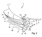
- the housing 7 is supported by means of the holder 8 on the cab 2 and the wind deflector 10 adjustable in such a way that for the housed in the housing 7 additional indicator 5 more different distances 13th or 13 'or 13 "and / or a plurality of different emission angles 14 or 14' or 14" relative to the respective vehicle side 4 are adjustable.
- Two different settings of the housing 7 are shown by way of example in FIG. 2, wherein the reference numerals in the position with the smallest distance 13 or with the smallest emission angle 14 are unchanged, in the position with the average distance 13 'or with the average emission angle 14 'are provided with a single "'" and in the position with the largest distance 13 "or with the largest radiation angle 14" with a double line "'".
- the housing 7 is mounted pivotably about a substantially vertical pivot axis 15 relative to the cab 2.
- the pivot axis 15 is in Fig. 2 substantially perpendicular to the plane of the drawing.
- the distance 13 and the radiation angle 14 of the auxiliary indicator light changes 5.
- the radiation angle 14 is measured from the respective vehicle side 4 to a straight line 16, on the one hand by the pivot axis 15 and on the other hand at a light exit end 17th of the housing 7 intersects a line 18 which defines a desired minimum beam angle for a certain width of a construction or semitrailer of the commercial vehicle 1, which the additional indicator 5 must have in order to be sufficiently reliably recognized by the subsequent traffic at the respective body or semi-trailer width to be able to.
- FIG. 1 Correspondingly, in FIG.
- Abstralwinkel 14, 14 ', 14 “must not exceed a desired or legally prescribed maximum emission angle, which is between a reference point of the auxiliary indicator 5 and a mounting edge, for example, about 5 ° the farther said reference point by adjusting or swinging the Additional indicator 5 comes to the outside, the larger the body width can be selected.
- the pivot axis 15 is arranged at an end or end portion of the housing 7 remote from the light exit end 17.
- the cab 2 can be adapted without much effort to different widths superstructures or semi-trailers. In particular, this simplifies the mass production of different types of vehicles. Likewise, one and the same vehicle 1 can be equipped with different width superstructures or semi-trailers depending on the application. The then required adjustment of the additional indicator lights 5 can be particularly easily implemented by means of the invention.
- the holder 8 is formed so that the respectively set relative position between the housing 7 and the cab 2 can be locked manually or by means of a corresponding tool. This can ensure that the set relative position does not change automatically when driving.
- the respective vehicle 1 is configured for coupling structures of different widths and / or semitrailers, it is expedient to select the distances 13 or emission angle 14 that can be set for the additional direction indicators 5, that at least the required minimum radiation angle 18 is adjustable for all occurring body or trailer widths. That is, the adjustability of the housing 7 is matched to the possible vehicle variants.
- the holder 8 may include a grid, so that the distances 13 and the radiation angle 14 are not continuously adjustable, but in a predetermined pitch.
- this grid size is matched to the standard widths of connectable to the commercial vehicle 1 bodies or semi-trailer. In this way, the adaptation of the cab 2 to the respective body or semi-trailer width can be carried out particularly easily and safely.
- auxiliary indicator 5 has increased accessibility when their maximum distance 13 and their maximum beam angle 14 is set. Improved accessibility facilitates maintenance, in particular the replacement of bulbs, such as e.g. Light bulbs.
- a maintenance position may be provided for the housing 7, in which the housing 7 is adjustable. For this maintenance position, the distance 13 or the radiation angle 14 is chosen so large that the additional indicator 5 has a particularly high accessibility for maintenance or the like.
- distance 13 or radiation angle 14 in this maintenance position can be so great that no proper driving operation of the vehicle 1 is possible in this maintenance position, which means that the maintenance position is not an operating position, but an impermissibly large distance 13 or one inadmissible has large-emitting radiation angle 14.
Landscapes
- Engineering & Computer Science (AREA)
- Mechanical Engineering (AREA)
- Lighting Device Outwards From Vehicle And Optical Signal (AREA)
- Vehicle Waterproofing, Decoration, And Sanitation Devices (AREA)
Claims (7)
- Véhicule utilitaire, en particulier camion,- comprenant une cabine de conduite (2) sur laquelle est disposé, de chaque côté (4) du véhicule, au moins un clignotant supplémentaire (5) qui, lors de son actionnement, diffuse la lumière de son clignotant (6) en direction de l'arrière du véhicule,- où chaque clignotant supplémentaire (5) est logé dans un carter (7) qui est fixé de manière orientable sur la cabine de conduite (2), de manière telle que, pour le clignotant supplémentaire respectif (5), plusieurs écartements (13) et/ou angles de rayonnement (14) soient réglables par rapport au côté respectif (4) du véhicule,- où chaque carter (7) est placé sur la cabine de conduite (2) en étant orientable par pivotement autour d'un axe de pivotement (15) pratiquement vertical,- où l'axe de pivotement respectif (15) est disposé dans une partie du carter respectif (7), qui est éloignée d'une extrémité de sortie de lumière (17) du carter respectif (7),- où le carter respectif (7) est disposé sur la cabine de conduite (2), dans une zone de transition (9) dans laquelle une partie avant (3) passe dans le côté respectif (4) du véhicule,- où le carter respectif (7) est disposé au-dessous d'un pare-brise (19) de la cabine de conduite (2).
- Véhicule utilitaire selon la revendication 1, caractérisé en ce qu'une fixation (8), avec laquelle le carter respectif (7) est fixé sur la cabine de conduite (2), de façon orientable, est conçue de manière telle, que la position relative du carter (7), respectivement réglée, puisse être verrouillée.
- Véhicule utilitaire selon la revendication 1 ou 2, caractérisé en ce que le carter respectif (7) est disposé sur un pare-chocs (12) ou sur un élément déflecteur (10) ou sur un panneau angulaire (11) de la cabine de conduite (2).
- Véhicule utilitaire selon l'une quelconque des revendications 1 à 3, caractérisé en ce que le carter respectif (7) est intégré, de façon aérodynamique, dans un contour extérieur de la cabine de conduite (2).
- Véhicule utilitaire selon l'une quelconque des revendications 1 à 4, caractérisé en ce que le véhicule utilitaire (1), derrière la cabine de conduite (2), est conçu pour l'attelage de différents éléments de superstructure ou semi-remorques qui se différencient les uns des autres, concernant leur largeur, où les écartements (13) et/ou angles de rayonnement (14), réglables pour les clignotants supplémentaires (5), sont réglés sur les différentes largeurs.
- Véhicule utilitaire selon la revendication 5, caractérisé en ce que le carter (7) est orientable en étant tramé, où une mesure de trame, qui prédéfinit les écartements (13) et/ou angles de rayonnement (14) réglables pour les clignotants supplémentaires (5), est réglée sur les différentes largeurs des éléments de superstructure ou semi-remorques.
- Véhicule utilitaire selon l'une quelconque des revendications 1 à 6, caractérisé en ce que chaque carter (7) est orientable dans une position d'entretien dans laquelle le clignotant supplémentaire respectif (5) présente un grand écartement (13) et/ou angle de rayonnement (14) non admissible pour une conduite réglementaire du véhicule, et qui est appropriée pour des travaux d'entretien sur le clignotant supplémentaire respectif (5).
Applications Claiming Priority (3)
| Application Number | Priority Date | Filing Date | Title |
|---|---|---|---|
| DE2002160785 DE10260785B4 (de) | 2002-12-23 | 2002-12-23 | Nutzfahrzeug, insbesondere Lastkraftwagen |
| DE10260785 | 2002-12-23 | ||
| PCT/EP2003/013135 WO2004058538A1 (fr) | 2002-12-23 | 2003-11-22 | Vehicule utilitaire, notamment camion |
Publications (2)
| Publication Number | Publication Date |
|---|---|
| EP1575802A1 EP1575802A1 (fr) | 2005-09-21 |
| EP1575802B1 true EP1575802B1 (fr) | 2006-06-21 |
Family
ID=32477949
Family Applications (1)
| Application Number | Title | Priority Date | Filing Date |
|---|---|---|---|
| EP03767612A Expired - Lifetime EP1575802B1 (fr) | 2002-12-23 | 2003-11-22 | Vehicule utilitaire, notamment camion avec clignotants supplementaires |
Country Status (4)
| Country | Link |
|---|---|
| EP (1) | EP1575802B1 (fr) |
| BR (1) | BR0317657A (fr) |
| DE (2) | DE10260785B4 (fr) |
| WO (1) | WO2004058538A1 (fr) |
Families Citing this family (2)
| Publication number | Priority date | Publication date | Assignee | Title |
|---|---|---|---|---|
| AT412778B (de) * | 2003-09-29 | 2005-07-25 | Man Sonderfahrzeuge Ag | Kommunales strassen- und winterdienstfahrzeug |
| DE102005037710A1 (de) * | 2005-08-10 | 2007-02-22 | Daimlerchrysler Ag | Nutzfahrzeug mit Fahrerhaus und Seitenleuchte |
Family Cites Families (22)
| Publication number | Priority date | Publication date | Assignee | Title |
|---|---|---|---|---|
| BE496870A (fr) * | ||||
| DE715400C (de) * | 1940-06-27 | 1941-12-20 | Dr Jur Heinrich Borgmann | Antriebselektromagnet fuer den Winkarm von Fahrtrichtungsanzeigern |
| US2571130A (en) * | 1948-02-16 | 1951-10-16 | Arnold E Hargis | Disappearing clearance light for truck bodies |
| US2665418A (en) * | 1950-12-07 | 1954-01-05 | Dearborn Motors Corp | Warning light for vehicles |
| GB782164A (en) * | 1954-05-11 | 1957-09-04 | Frank Gabriel Singleton | Improvements in or relating to indicating or warning light fittings for road vehicles |
| US2825888A (en) * | 1956-10-26 | 1958-03-04 | Frederick W Oldenburg | Turn signal for vehicle bodies |
| FR1586054A (fr) * | 1968-10-22 | 1970-02-06 | ||
| DE2542920C3 (de) * | 1975-09-26 | 1979-10-25 | Dr.Ing.H.C. F. Porsche Ag, 7000 Stuttgart | Stoßfänger für Fahrzeuge, insbesondere Kraftfahrzeuge |
| US4234908A (en) * | 1978-07-10 | 1980-11-18 | Caterpillar Tractor Co. | Storable light assembly for vehicles |
| DE7911535U1 (de) * | 1979-04-20 | 1979-09-13 | Magirus-Deutz Ag, 7900 Ulm | Frontlenkerfahrzeug |
| DE3044313C2 (de) * | 1980-11-25 | 1984-07-19 | Ford-Werke AG, 5000 Köln | Befestigungsvorrichtung für in Mulden von Karosserieteilen aufgenommene Bauteile |
| DE3327588A1 (de) * | 1983-07-30 | 1985-02-14 | Iveco Magirus AG, 7900 Ulm | Fahrzeugleuchte |
| DE8326550U1 (de) * | 1983-09-15 | 1983-12-29 | Iveco Magirus AG, 7900 Ulm | Fahrzeug mit fahrtrichtungsanzeigern im bereich von luftleitkoerpern |
| DE3525198A1 (de) * | 1985-07-15 | 1987-01-15 | Opel Adam Ag | Leuchteneinheit |
| DE4011703C1 (fr) * | 1990-04-11 | 1991-10-02 | Hella Kg Hueck & Co, 4780 Lippstadt, De | |
| DE4014577C1 (en) * | 1990-05-07 | 1991-10-24 | Mercedes-Benz Aktiengesellschaft, 7000 Stuttgart, De | Air guide for vehicle cab - has arcuate profile panel extending past door gap and swivelling to allow door opening |
| DE4112794C1 (en) * | 1991-04-19 | 1992-09-10 | Hella Kg Hueck & Co, 4780 Lippstadt, De | Dipped headlamp arrangement for vehicle - has reflector and lamp disc pivoted relative to frame via locking lever |
| DE4142582A1 (de) * | 1991-12-21 | 1993-06-24 | Porsche Ag | Stossfaenger fuer fahrzeuge, insbesondere kraftfahrzeuge |
| JP3148399B2 (ja) * | 1992-09-28 | 2001-03-19 | 富士通株式会社 | 半導体装置の製造方法 |
| DE19530913A1 (de) * | 1995-08-23 | 1997-02-27 | Happich Gmbh Gebr | Sicherheitsvorrichtung für Fahrzeuge |
| DE10000006C2 (de) * | 2000-01-03 | 2003-09-18 | Herbert Michels | Einstiegsverkleidung für ein Fahrerhaus eines Lastkraftwagens |
| EP1114748A3 (fr) * | 2000-01-07 | 2004-01-02 | Hans Dominik | Dispositif d'éclairage |
-
2002
- 2002-12-23 DE DE2002160785 patent/DE10260785B4/de not_active Expired - Fee Related
-
2003
- 2003-11-22 DE DE50304003T patent/DE50304003D1/de not_active Expired - Lifetime
- 2003-11-22 WO PCT/EP2003/013135 patent/WO2004058538A1/fr not_active Ceased
- 2003-11-22 EP EP03767612A patent/EP1575802B1/fr not_active Expired - Lifetime
- 2003-11-22 BR BR0317657-6A patent/BR0317657A/pt not_active IP Right Cessation
Also Published As
| Publication number | Publication date |
|---|---|
| BR0317657A (pt) | 2005-12-06 |
| DE10260785A1 (de) | 2004-07-08 |
| DE10260785B4 (de) | 2005-04-21 |
| EP1575802A1 (fr) | 2005-09-21 |
| WO2004058538A1 (fr) | 2004-07-15 |
| DE50304003D1 (de) | 2006-08-03 |
Similar Documents
| Publication | Publication Date | Title |
|---|---|---|
| EP0895897B1 (fr) | Véhicule industriel avec mirroir monté à l'avant | |
| EP1052151B1 (fr) | Pare-chocs de véhicules automobiles | |
| DE102013008593A1 (de) | Frontlenker-Nutzkraftfahrzeug, insbesondere Frontlenker-Lastkraftfahrzeug, mit frontseitig temporär und formvariabel, insbesondere nasenförmig und haubenförmig einstellbaren sowie nachrüstbaren Luftleitflächen | |
| EP1600335B1 (fr) | Unité d'absorption des chocs pour la partie avant d'une véhicule | |
| EP1637438A2 (fr) | Véhicule utilitaire, en particulier un véhilcue de collectes des ordures ménagères ou un véhicule communal, présentant une cabine à accès rabaissé | |
| EP2042410A2 (fr) | Véhicule agricole | |
| DE102005048142B4 (de) | Zugfahrzeug für Zugfahrzeug-Anhängerkombinationen mit geschwindigkeitsabhängig verstellbarer Windleiteinrichtung | |
| EP1575802B1 (fr) | Vehicule utilitaire, notamment camion avec clignotants supplementaires | |
| DE202013004691U1 (de) | Frontlenker-Nutzkraftfahrzeug, insbesondere Frontlenker- Lastkraftfahrzeug, mit frontseitig temporär und formvariabel, insbesondere nasenförmig und haubenförmig einstellbaren sowie nachrüstbaren Luftleitflächen | |
| DE102004043544B4 (de) | Spoiler | |
| WO2021110451A1 (fr) | Véhicule à moteur doté d'un système de nettoyage de vitre | |
| EP0349746B1 (fr) | Dispositif de guidage de l'air pour camion et semi-remorque | |
| EP4069578B1 (fr) | Véhicule automobile à becquet de toit | |
| DE19928104B4 (de) | Klappbarer Heckunterfahrschutz | |
| WO2021083706A1 (fr) | Élément de régulation de l'air pour un véhicule automobile | |
| DE19534567A1 (de) | Hebe- und Rangiergerät für Kraftfahrzeuge und mit einer solchen Vorrichtung ausgerüstetes Kraftfahrzeug | |
| EP1717119A1 (fr) | Structure de sechage pour une installation de lavage pour véhicule | |
| DE10319881B4 (de) | Außenspiegelvorrichtung | |
| DE10052837B4 (de) | Kraftfahrzeug | |
| DE102006037028B4 (de) | Hochdach für Nutzfahrzeug | |
| EP0757945A2 (fr) | Véhicule agricole | |
| EP0133637A1 (fr) | Dispositif porte-outils frontal sur un véhicule à capotage frontal, utilisable pour l'agriculture et/ou les travaux publics, en particulier sur un tracteur agricole | |
| DE102005019778A1 (de) | Spiegelgehäuse | |
| EP1518966A1 (fr) | Véhicule communal pour l'entretien des routes et le service d'hiver | |
| DE102024124502A1 (de) | Nutzfahrzeug mit Trittstufe |
Legal Events
| Date | Code | Title | Description |
|---|---|---|---|
| PUAI | Public reference made under article 153(3) epc to a published international application that has entered the european phase |
Free format text: ORIGINAL CODE: 0009012 |
|
| 17P | Request for examination filed |
Effective date: 20050511 |
|
| AK | Designated contracting states |
Kind code of ref document: A1 Designated state(s): AT BE BG CH CY CZ DE DK EE ES FI FR GB GR HU IE IT LI LU MC NL PT RO SE SI SK TR |
|
| GRAP | Despatch of communication of intention to grant a patent |
Free format text: ORIGINAL CODE: EPIDOSNIGR1 |
|
| RBV | Designated contracting states (corrected) |
Designated state(s): DE FR IT SE TR |
|
| GRAS | Grant fee paid |
Free format text: ORIGINAL CODE: EPIDOSNIGR3 |
|
| GRAA | (expected) grant |
Free format text: ORIGINAL CODE: 0009210 |
|
| AK | Designated contracting states |
Kind code of ref document: B1 Designated state(s): DE FR IT SE TR |
|
| PG25 | Lapsed in a contracting state [announced via postgrant information from national office to epo] |
Ref country code: IT Free format text: LAPSE BECAUSE OF FAILURE TO SUBMIT A TRANSLATION OF THE DESCRIPTION OR TO PAY THE FEE WITHIN THE PRESCRIBED TIME-LIMIT;WARNING: LAPSES OF ITALIAN PATENTS WITH EFFECTIVE DATE BEFORE 2007 MAY HAVE OCCURRED AT ANY TIME BEFORE 2007. THE CORRECT EFFECTIVE DATE MAY BE DIFFERENT FROM THE ONE RECORDED. Effective date: 20060621 |
|
| REG | Reference to a national code |
Ref country code: SE Ref legal event code: TRGR |
|
| REF | Corresponds to: |
Ref document number: 50304003 Country of ref document: DE Date of ref document: 20060803 Kind code of ref document: P |
|
| ET | Fr: translation filed | ||
| RAP2 | Party data changed (patent owner data changed or rights of a patent transferred) |
Owner name: DAIMLERCHRYSLER AG |
|
| PLBE | No opposition filed within time limit |
Free format text: ORIGINAL CODE: 0009261 |
|
| STAA | Information on the status of an ep patent application or granted ep patent |
Free format text: STATUS: NO OPPOSITION FILED WITHIN TIME LIMIT |
|
| 26N | No opposition filed |
Effective date: 20070322 |
|
| REG | Reference to a national code |
Ref country code: FR Ref legal event code: CA Ref country code: FR Ref legal event code: CD |
|
| PGFP | Annual fee paid to national office [announced via postgrant information from national office to epo] |
Ref country code: TR Payment date: 20101025 Year of fee payment: 8 Ref country code: IT Payment date: 20101124 Year of fee payment: 8 |
|
| PGFP | Annual fee paid to national office [announced via postgrant information from national office to epo] |
Ref country code: FR Payment date: 20111214 Year of fee payment: 9 Ref country code: SE Payment date: 20111130 Year of fee payment: 9 |
|
| PG25 | Lapsed in a contracting state [announced via postgrant information from national office to epo] |
Ref country code: SE Free format text: LAPSE BECAUSE OF NON-PAYMENT OF DUE FEES Effective date: 20121123 |
|
| REG | Reference to a national code |
Ref country code: FR Ref legal event code: ST Effective date: 20130731 |
|
| PG25 | Lapsed in a contracting state [announced via postgrant information from national office to epo] |
Ref country code: IT Free format text: LAPSE BECAUSE OF NON-PAYMENT OF DUE FEES Effective date: 20121122 |
|
| PG25 | Lapsed in a contracting state [announced via postgrant information from national office to epo] |
Ref country code: FR Free format text: LAPSE BECAUSE OF NON-PAYMENT OF DUE FEES Effective date: 20121130 |
|
| PG25 | Lapsed in a contracting state [announced via postgrant information from national office to epo] |
Ref country code: TR Free format text: LAPSE BECAUSE OF NON-PAYMENT OF DUE FEES Effective date: 20121122 |
|
| PGFP | Annual fee paid to national office [announced via postgrant information from national office to epo] |
Ref country code: DE Payment date: 20150129 Year of fee payment: 12 |
|
| REG | Reference to a national code |
Ref country code: DE Ref legal event code: R119 Ref document number: 50304003 Country of ref document: DE |
|
| PG25 | Lapsed in a contracting state [announced via postgrant information from national office to epo] |
Ref country code: DE Free format text: LAPSE BECAUSE OF NON-PAYMENT OF DUE FEES Effective date: 20160601 |