EP1576794B1 - Sprachkommunikationsvorrichtung - Google Patents
Sprachkommunikationsvorrichtung Download PDFInfo
- Publication number
- EP1576794B1 EP1576794B1 EP03814546A EP03814546A EP1576794B1 EP 1576794 B1 EP1576794 B1 EP 1576794B1 EP 03814546 A EP03814546 A EP 03814546A EP 03814546 A EP03814546 A EP 03814546A EP 1576794 B1 EP1576794 B1 EP 1576794B1
- Authority
- EP
- European Patent Office
- Prior art keywords
- characteristic
- frequency characteristic
- transmitter
- band
- receiver
- Prior art date
- Legal status (The legal status is an assumption and is not a legal conclusion. Google has not performed a legal analysis and makes no representation as to the accuracy of the status listed.)
- Expired - Lifetime
Links
- 238000004891 communication Methods 0.000 title claims description 98
- 238000012937 correction Methods 0.000 claims description 54
- 239000002131 composite material Substances 0.000 claims 2
- 238000005259 measurement Methods 0.000 claims 1
- 230000005540 biological transmission Effects 0.000 description 11
- 238000010586 diagram Methods 0.000 description 6
- 230000004044 response Effects 0.000 description 6
- 230000002238 attenuated effect Effects 0.000 description 4
- 238000009434 installation Methods 0.000 description 4
- 238000000034 method Methods 0.000 description 4
- 238000010276 construction Methods 0.000 description 2
- 230000003044 adaptive effect Effects 0.000 description 1
- 230000008859 change Effects 0.000 description 1
- 238000013461 design Methods 0.000 description 1
- 238000001514 detection method Methods 0.000 description 1
- 230000002708 enhancing effect Effects 0.000 description 1
- 230000008569 process Effects 0.000 description 1
- 230000007480 spreading Effects 0.000 description 1
- 238000012360 testing method Methods 0.000 description 1
Images




Classifications
-
- H—ELECTRICITY
- H04—ELECTRIC COMMUNICATION TECHNIQUE
- H04M—TELEPHONIC COMMUNICATION
- H04M1/00—Substation equipment, e.g. for use by subscribers
- H04M1/253—Telephone sets using digital voice transmission
- H04M1/2535—Telephone sets using digital voice transmission adapted for voice communication over an Internet Protocol [IP] network
-
- H—ELECTRICITY
- H04—ELECTRIC COMMUNICATION TECHNIQUE
- H04M—TELEPHONIC COMMUNICATION
- H04M1/00—Substation equipment, e.g. for use by subscribers
- H04M1/60—Substation equipment, e.g. for use by subscribers including speech amplifiers
-
- H—ELECTRICITY
- H04—ELECTRIC COMMUNICATION TECHNIQUE
- H04M—TELEPHONIC COMMUNICATION
- H04M3/00—Automatic or semi-automatic exchanges
- H04M3/40—Applications of speech amplifiers
-
- H—ELECTRICITY
- H04—ELECTRIC COMMUNICATION TECHNIQUE
- H04M—TELEPHONIC COMMUNICATION
- H04M7/00—Arrangements for interconnection between switching centres
- H04M7/006—Networks other than PSTN/ISDN providing telephone service, e.g. Voice over Internet Protocol (VoIP), including next generation networks with a packet-switched transport layer
-
- H—ELECTRICITY
- H04—ELECTRIC COMMUNICATION TECHNIQUE
- H04M—TELEPHONIC COMMUNICATION
- H04M7/00—Arrangements for interconnection between switching centres
- H04M7/006—Networks other than PSTN/ISDN providing telephone service, e.g. Voice over Internet Protocol (VoIP), including next generation networks with a packet-switched transport layer
- H04M7/0066—Details of access arrangements to the networks
- H04M7/0069—Details of access arrangements to the networks comprising a residential gateway, e.g. those which provide an adapter for POTS or ISDN terminals
Definitions
- the present invention relates to a voice communications apparatus, and more particularly, to a voice communications apparatus built in, or accommodating, a telephone set and also to a voice communications system including the same.
- the types, or characteristics, of the telephone sets 11 and 12, respectively connected to the voice communications apparatus 10 and 20, may not be fixed.
- the transmitter F characteristic corrector circuit 31 should preferably be configured to be capable of varying the correction frequency characteristic, so that an engineer, for example, can manipulate its adjuster element to adjust the characteristic at the installation site.
- the voice signal output from the microphone 11S has a flat frequency characteristic throughout the entire voice band, e.g. in a frequency band below 8 kHz inclusive, as shown in FIG. 6 , then the voice signal thus limited in frequency by the telephone set body 11B has a lower-frequency component below 300 Hz inclusive and a higher-frequency component above 3,400 Hz inclusive attenuated, as shown in FIG. 4A .
- the voice signal output from the telephone set body 11B is in turn input to the voice communications apparatus 10.
- the above IP packets, transmitted over the IP network 2, are input to the other voice communications apparatus, or receiving station, 20.
- the IP packet-to-voice signal converter circuit 41 decomposes the IP packets thus arrived to thereby restore the original voice signal and delivers the restored voice signal to the receiver F characteristic corrector circuit 42.
- the receiver F characteristic corrector circuit 42 with the correction frequency characteristic of FIG. 5C raises the frequency band components, which will be attenuated by the receiver characteristic, to thereby output a voice signal having the frequency characteristic of FIG. 5B .
- the resulting voice signal is fed to the receiving telephone set 12.
- the alternative embodiment not only achieves the same advantages as the earlier described embodiment, but also further enhances communication quality by allowing an optimum correction frequency characteristic for a given type of telephone set to be selected.
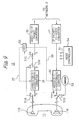
- the switches 51A through 51D are configured to establish a particular signal path for each of the usual mode and F characteristic setting mode.
- the mode controller 54 connects the switches 51A and 51B to the terminals b thereof, connects the switch 51C to its terminal a and connects the switch 51D to its terminal c, and then causes the frequency analyzer 52 and white noise generator 53 to start operating.
- the white noise generator 53 generates white noise.
- the white noise thus generated is effected by the receiver characteristic of the telephone set body 11B and then output from the loudspeaker 11R in the form of sound.
- the resulting sound is captured by the microphone 11S, effected by the transmitter characteristic of the telephone set body 11B, and then input to the frequency analyzer 52 via the transmitter F characteristic corrector circuit 31.
- the illustrative embodiment measures the transmitter and receiver characteristics of the telephone set 11 or 12 connected to the voice communications apparatus 10 or 20, respectively, and then selects appropriate correction frequency characteristics. It follows that particular correction frequency characteristics can be set for each telephone set 11 or 12, further enhancing communication quality. Of course, the illustrative embodiment also achieves the same advantages as the embodiment described earlier.
- FIG. 10 A still further alternative embodiment of the voice communications system in accordance with the present invention will be described with reference to FIG. 10 hereinafter.
- the still further embodiment is similar to the embodiment shown in FIG. 9 except for the following.
- structural parts and elements like those shown in FIG. 9 are designated with the identical reference numerals and will not be described specifically in order to avoid redundancy.
- the instant embodiment causes the voice communications apparatus 10 or 20 to operate in a different manner from the apparatus 10 or 20 of the FIG. 9 embodiment in the F characteristic setting mode.
- FIG. 10 shows only the voice communication apparatus when applied to the voice communications apparatus 10. The same will be applicable to the voice communications apparatus 20.
- the mode controller 54 connects the switches 51A, 51B and 51C to the terminals a thereof, and then causes the frequency analyzer 52 to start operating.
- the microphone 11S of the telephone set 11 generates a signal representative of background noise caught thereby.
- background noise is assumed to be white noise. Consequently, a signal, derived from the background noise and reflecting the transmitter characteristic of the telephone set body 11B, is input to the frequency analyzer 52.
- the frequency analyzer 52 determines the transmitter characteristic of the telephone set 11 and then causes the transmitter and receiver F characteristic corrector circuits 31 and 42 to select respective correction frequency characteristics matching with the transmitter characteristic.
- the mode controller 54 connects all of the switches 51A, 51B and 51C to the terminals b thereof and then establishes the usual mode.
- the illustrative embodiment of the voice communications device applied to the other voice communications device 20 will of course operate in the same manner as described above.
- the illustrative embodiment achieves the same advantages as the embodiment shown in FIG. 9 .
- FIG. 11 for describing still another alternative embodiment of the voice communications system in accordance with the present invention.
- the instant, illustrative embodiment is also similar to the embodiment shown in FIG. 9 except for the points describedbelow. With the embodiment also, like structural parts and elements are designated with the identical reference numerals and will not be described specifically in order to avoid redundancy.
- FIG. 11 only the one voice communications apparatus 10 is shown. However, as stated earlier, the other voice communications apparatus 20 may of course be of the same structure as the one apparatus 10.
- the voice communications apparatus 10 of the illustrative embodiment is generally made up of an apparatus body 10A and an attachment 10B used to measure F frequency characteristics.
- the attachment 10B configured to operate only in the F characteristic setting mode, may be adapted to be manually coupled to the apparatus body 10A by, e.g. an installing engineer.
- the attachment 10B may be adapted to be fixedly coupled to and mechanically enclosed with the housing, not shown, of the apparatus body 10A, in which case an installer, for example, will take out the attachment 10B from the housing only in the F characteristic setting mode to operate it.
- the engineer positions the attachment 10B such that the loudspeaker 55 and microphone 56 face the microphone 11S and loudspeaker 11R, respectively, of a handset 13 of the telephone set 11, prior to selecting the F characteristic setting mode.
- the attachment 10B may preferably be enclosed with its housing, not shown, which has a contour or shape configured such that when the handset 13 is put thereon by hand, the loudspeaker 55 and microphone 56 will naturally face the microphone 11S and loudspeaker 11R, respectively.
- the mode controller 54 When the F characteristic setting mode is selected, the mode controller 54 first connects the switches 57A and 57B to the terminals a and b thereof, respectively. The controller 54 also turns off the switch 57C, i.e. connects it to neither its terminal a nor its terminal b . The controller 54 connects the switch 57D to its terminal a , and tuns off the switch 57E. Subsequently, the mode controller 54 causes the white noise generator 53 and frequency analyzer 52 to start operating.
- the white noise generator 53 in turn generates white noise.
- the white noise thus generated is transduced by the loudspeaker 55 into sound, which is in turn output from the loudspeaker 55 and then caught by the microphone 11S of the telephone set 11, which is connected to the voice communications apparatus 10.
- a signal, reflecting the transmitter characteristic of the telephone set body 11B is input to the frequency analyzer 52.
- the frequency analyzer 52 determines the transmitter characteristic of the telephone set 11 and then causes the transmitter F characteristic corrector circuit 31 to select a correction frequency characteristic matching with the transmitter characteristic.
- the mode controller 54 connects the switch 57A to its terminal b , turns off the switch 51B, i.e. connects it to neither its terminal a nor its terminal b , connects the switches 51C to respective terminals b thereof, and turns on the switch 57E.
- the mode controller 54 then causes the white noise generator 53 and frequency analyzer 52 to start operating.
- White noise produced from the white noise generator 53 is effected by the receiver characteristic of the telephone set body 11B, output via the loudspeaker 11R, captured by the microphone 56, and then delivered to the frequency analyzer 52 in the form of a signal.
Landscapes
- Engineering & Computer Science (AREA)
- Signal Processing (AREA)
- Computer Networks & Wireless Communication (AREA)
- Telephone Function (AREA)
- Cable Transmission Systems, Equalization Of Radio And Reduction Of Echo (AREA)
- Telephonic Communication Services (AREA)
Claims (8)
- Sprachkommunikationsvorrichtung (10), die dazu eingerichtet ist, sich zwischen eine Telefonanlage (11) und einen Breitband-Kommunikationspfad einzuschalten, der ein Kommunikationsband aufweist, welches breiter als ein durch eine Sendereigenschaft und eine Empfängereigenschaft der Telefonanlage (11) beschränktes Sprachband ist, umfassend:eine Senderfrequenzeigenschaftskorrekturschaltung (31), welche eine erste Korrekturfrequenzeigenschaft zum Korrigieren einer Frequenzeigenschaft eines von der Telefonanlage (11) eingegebenen Signals durch Abflachen einer Frequenzeigenschaft eines Signals in dem Kommunikationsband des Breitband-Kommunikationspfades aufweist; undeine Empfängerfrequenzeigenschaftskorrekturschaltung (42), welche eine zweite Korrekturfrequenzeigenschaft zum Korrigieren einer Frequenzeigenschaft eines zur Telefonanlage (11) einzugebenden Signals durch Abflachen einer Frequenzeigenschaft eines Signals in dem Kommunikationsband des Breitband-Kommunikationspfades aufweist.
- Vorrichtung (10) in Übereinstimmung mit Anspruch 1, wobei:die erste Korrekturfrequenzeigenschaft derart ist, dass in einem Kommunikationsband des Breitband-Kommunikationspfades eine zusammengesetzte Frequenzeigenschaft der ersten Korrekturfrequenzeigenschaft mit der Sendereigenschaft flach ist,die zweite Korrekturfrequenzeigenschaft derart ist, dass in dem Kommunikationsband des Breitband-Kommunikationspfades eine zusammengesetzte Frequenzkomponente der zweiten Korrekturfrequenzeigenschaft mit der Empfängereigenschaft flach ist.
- Vorrichtung (10) in Übereinstimmung mit Anspruch 1, wobei die erste Korrekturfrequenzeigenschaft und die zweite Korrekturfrequenzeigenschaft veränderlich sind.
- Vorrichtung (10) in Übereinstimmung mit Anspruch 2, wobei die erste Korrekturfrequenzeigenschaft und die zweite Korrekturfrequenzeigenschaft veränderlich sind.
- Vorrichtung (10) in Übereinstimmung mit Anspruch 3, ferner umfassend eine Korrekturfrequenzeigenschaftseinstellschaltung (52, 53) zum Messen der Sendereigenschaft und der Empfängereigenschaft der Telefonanlage (11) und zum Einstellen der ersten Korrekturfrequenzeigenschaft und der zweiten Korrekturfrequenzeigenschaft in Übereinstimmung mit Ergebnissen der Messung.
- Vorrichtung (10) in Übereinstimmung mit Anspruch 5, wobei die Korrekturfrequerizeigenschaftseinstellschaltung (52, 53) dazu ausgelegt ist, die gemessene Sendereigenschaft zu verwenden, um die gemessene Sendereigenschaft als die Empfängereigenschaft der Telefonanlage (11) zu übernehmen.
- Vorrichtung (10) in Übereinstimmung mit Anspruch 5, wobei die Korrekturfrequenzeigenschaftseinstellschaltung (52, 53) umfasst:einen Weißrauschenerzeuger (53) zum Erzeugen eines weißen Rauschens;eine Sendereigenschaftsmessschaltung (52) zum Ausgeben des weißen Rauschens in einer Schallform und zum Verarbeiten eines Signals von einem Mikrofon (11S), welches das weiße Rauschen aufgenommen und umgewandelt hat, um die Sendereigenschaft zu messen; undeine Empfängereigenschaftsmessschaltung (52) zum Ausgeben des weißen Rauschens, welches durch den Weißrauschenerzeuger (53) von einem Lautsprecher (11R) erzeugt wird, und zum Verarbeiten des ausgegebenen weißen Rauschens, um die Empfängereigenschaft zu messen;wobei die Korrekturfrequenzeigenschaftseinstellschaltung (52, 53) dazu ausgelegt ist, die erste Korrekturfrequenzeigenschaft und die zweite Korrekturfrequenzeigenschaft in Übereinstimmung mit der gemessenen Sendereigenschaft bzw. der Empfängereigenschaft einzustellen.
- Sprachkommunikationssystem zum Verbinden von zwei Telefonanlagen (11, 12) über einen Breitband-Kommunikationspfad, der ein Kommunikationsband aufweist, welches breiter als ein durch eine Sendereigenschaft und eine Ernpfängereigenschaft von jeder der zwei Telefonanlagen (11, 12) beschränktes Sprachband ist, wobei jede von den zwei Telefonanlagen mit dem Breitband-Kommunikationspfad (11, 12) über eine Sprachkommunikationsvorrichtung (10, 20) gemäß einem der Ansprüche 1 bis 7 verbunden ist.
Applications Claiming Priority (5)
| Application Number | Priority Date | Filing Date | Title |
|---|---|---|---|
| JP2002379082 | 2002-12-27 | ||
| JP2002379082 | 2002-12-27 | ||
| JP2003071826 | 2003-03-17 | ||
| JP2003071826A JP4586330B2 (ja) | 2002-12-27 | 2003-03-17 | 音声通信装置及び音声通信システム |
| PCT/JP2003/016546 WO2004062249A1 (en) | 2002-12-27 | 2003-12-24 | Voice communications apparatus |
Publications (2)
| Publication Number | Publication Date |
|---|---|
| EP1576794A1 EP1576794A1 (de) | 2005-09-21 |
| EP1576794B1 true EP1576794B1 (de) | 2010-03-10 |
Family
ID=32716307
Family Applications (1)
| Application Number | Title | Priority Date | Filing Date |
|---|---|---|---|
| EP03814546A Expired - Lifetime EP1576794B1 (de) | 2002-12-27 | 2003-12-24 | Sprachkommunikationsvorrichtung |
Country Status (5)
| Country | Link |
|---|---|
| US (2) | US7792255B2 (de) |
| EP (1) | EP1576794B1 (de) |
| JP (1) | JP4586330B2 (de) |
| KR (1) | KR100973958B1 (de) |
| WO (1) | WO2004062249A1 (de) |
Families Citing this family (3)
| Publication number | Priority date | Publication date | Assignee | Title |
|---|---|---|---|---|
| FR2863802A1 (fr) * | 2003-12-11 | 2005-06-17 | France Telecom | Systeme de telephonie via un reseau numerique, perfectionne |
| JP4635942B2 (ja) * | 2006-04-05 | 2011-02-23 | 沖電気工業株式会社 | 帯域補正装置 |
| KR102443637B1 (ko) * | 2017-10-23 | 2022-09-16 | 삼성전자주식회사 | 네트워크 연결 정보에 기반하여 잡음 제어 파라미터를 결정하는 전자 장치 및 그의 동작 방법 |
Family Cites Families (35)
| Publication number | Priority date | Publication date | Assignee | Title |
|---|---|---|---|---|
| JP3085676B2 (ja) | 1989-10-30 | 2000-09-11 | 株式会社東芝 | 電話装置 |
| JPH04948A (ja) * | 1990-04-18 | 1992-01-06 | Nec Corp | ディジタル回線用電話機の通話特性装置 |
| JPH05347661A (ja) * | 1992-06-16 | 1993-12-27 | Matsushita Electric Ind Co Ltd | 電話装置 |
| JPH0630090A (ja) * | 1992-07-08 | 1994-02-04 | Mitsubishi Electric Corp | 音量制御機能付き電話機 |
| JPH08139789A (ja) * | 1994-11-14 | 1996-05-31 | Casio Comput Co Ltd | 無線通信装置における音声入力回路 |
| JPH0955778A (ja) * | 1995-08-15 | 1997-02-25 | Fujitsu Ltd | 音声信号の広帯域化装置 |
| AU1411297A (en) * | 1995-12-19 | 1997-07-14 | Motorola, Inc. | Method and apparatus for automatic frequency correction acquisition |
| US5802164A (en) | 1995-12-22 | 1998-09-01 | At&T Corp | Systems and methods for controlling telephone sound enhancement on a per call basis |
| JPH09261517A (ja) * | 1996-03-18 | 1997-10-03 | Canon Inc | ビデオカメラ及びその制御方法 |
| US6175565B1 (en) * | 1997-09-17 | 2001-01-16 | Nokia Corporation | Serial telephone adapter |
| US6288610B1 (en) * | 1998-03-19 | 2001-09-11 | Fujitsu Limited | Method and apparatus for correcting signals, apparatus for compensating for distortion, apparatus for preparing distortion compensating data, and transmitter |
| JP2000216911A (ja) * | 1999-01-27 | 2000-08-04 | Ricoh Co Ltd | 端末アダプタ装置 |
| US6480581B1 (en) * | 1999-06-22 | 2002-11-12 | Institute For Information Industry | Internet/telephone adapter device and method |
| JP2001036524A (ja) * | 1999-07-16 | 2001-02-09 | Matsushita Electric Ind Co Ltd | インターネット電話装置 |
| JP2001036625A (ja) * | 1999-07-21 | 2001-02-09 | Kenwood Corp | 通話装置におけるエコー量調整方法 |
| JP2001148723A (ja) * | 1999-11-18 | 2001-05-29 | Toyo Commun Equip Co Ltd | 難聴者用電話機システム |
| US6826174B1 (en) * | 2000-03-02 | 2004-11-30 | 3Com Corporation | Voice-over-IP interface for standard household telephone |
| JP3775156B2 (ja) * | 2000-03-02 | 2006-05-17 | ヤマハ株式会社 | 携帯電話機 |
| US7023987B1 (en) * | 2000-05-04 | 2006-04-04 | Televoce, Inc. | Method and apparatus for adapting a phone for use in network voice operations |
| EP1168734A1 (de) * | 2000-06-26 | 2002-01-02 | BRITISH TELECOMMUNICATIONS public limited company | Verfahren zur Reduzierung der Verzerrung in einer Sprachübertragung über Datennetze |
| JP2002077314A (ja) * | 2000-08-29 | 2002-03-15 | Matsushita Electric Ind Co Ltd | 高齢者向け電話機 |
| US7167451B1 (en) * | 2000-12-21 | 2007-01-23 | Cisco Technology, Inc. | User controlled audio quality for voice-over-IP telephony systems |
| US7574001B2 (en) * | 2000-12-28 | 2009-08-11 | Broadcom Corporation | Internet protocol telephone system |
| US20020106072A1 (en) | 2001-02-06 | 2002-08-08 | Apfel Russell J. | Method and apparatus for improving gain bandwidth paths |
| IL144158A (en) * | 2001-07-05 | 2011-06-30 | Mosaid Technologies Inc | Socket for connecting an analog telephone to a digital communications network that carries digital voice signals |
| JP3680009B2 (ja) | 2001-07-25 | 2005-08-10 | 株式会社東芝 | エコーキャンセラ |
| JP3862056B2 (ja) * | 2001-08-06 | 2006-12-27 | 三菱電機株式会社 | 通話装置アダプタ |
| JP2003078426A (ja) * | 2001-08-31 | 2003-03-14 | Nec Corp | 携帯端末装置の周波数補正方法 |
| JP2003071826A (ja) | 2001-09-04 | 2003-03-12 | Toray Ind Inc | 繊維補強モルタル用混和材料パック |
| US7391761B1 (en) * | 2001-12-21 | 2008-06-24 | At&T Delaware Intellectual Property, Inc. | System and method for voice over internet protocol using a standard telephone system |
| AU2003299591A1 (en) * | 2002-12-05 | 2004-06-30 | Symbolic Intelligence Enhanced Systems, Inc. | Virtual pbx based on sip and feature servers |
| US7113590B2 (en) * | 2003-03-07 | 2006-09-26 | Legerity, Inc. | Method and apparatus for a differential feedback in an active impedence feedback circuit |
| US8594078B2 (en) * | 2003-06-02 | 2013-11-26 | At&T Intellectual Property I, L.P. | Method and apparatus for stand-alone voice over internet protocol with POTS telephone support |
| US7313231B2 (en) * | 2003-09-02 | 2007-12-25 | At&T Bls Intellectual Property, Inc. | Methods, apparatus and computer program products for routing phone calls to a PSTN or a packet switched network based on called number |
| US7508928B1 (en) * | 2004-04-30 | 2009-03-24 | Sprint Spectrum L.P. | System and method for voice-over-packet calling with PSTN backup |
-
2003
- 2003-03-17 JP JP2003071826A patent/JP4586330B2/ja not_active Expired - Lifetime
- 2003-12-24 WO PCT/JP2003/016546 patent/WO2004062249A1/en not_active Ceased
- 2003-12-24 EP EP03814546A patent/EP1576794B1/de not_active Expired - Lifetime
- 2003-12-24 KR KR1020057012096A patent/KR100973958B1/ko not_active Expired - Fee Related
-
2005
- 2005-06-24 US US11/165,436 patent/US7792255B2/en active Active
-
2010
- 2010-07-07 US US12/805,006 patent/US7961855B2/en not_active Expired - Fee Related
Also Published As
| Publication number | Publication date |
|---|---|
| JP4586330B2 (ja) | 2010-11-24 |
| WO2004062249A1 (en) | 2004-07-22 |
| US7961855B2 (en) | 2011-06-14 |
| US20060013370A1 (en) | 2006-01-19 |
| JP2004254261A (ja) | 2004-09-09 |
| KR20050085911A (ko) | 2005-08-29 |
| EP1576794A1 (de) | 2005-09-21 |
| US20100272248A1 (en) | 2010-10-28 |
| US7792255B2 (en) | 2010-09-07 |
| KR100973958B1 (ko) | 2010-08-05 |
Similar Documents
| Publication | Publication Date | Title |
|---|---|---|
| JP2550914B2 (ja) | 折りたたみ型携帯電話装置 | |
| EP2822263A1 (de) | Kommunikationsvorrichtung mit Echounterdrückung | |
| US7286496B2 (en) | IP network communication device with facsimile communication function | |
| JP4507504B2 (ja) | 音声通信装置及び音声通信方法 | |
| US7961855B2 (en) | Voice communications apparatus | |
| KR20050088230A (ko) | 음성 통신 시스템 | |
| JP4255276B2 (ja) | 音声通信装置、電話機及び音声通信システム | |
| CN100531259C (zh) | 语音通信设备 | |
| GB2529142A (en) | Remote tuning and diagnostic interface for hands-free system | |
| JPH11196178A (ja) | レベル自動調整装置 | |
| JP4198075B2 (ja) | 音声通信装置及び電話機 | |
| JPH01123554A (ja) | 電話機 | |
| JP3781524B2 (ja) | 電話システム | |
| JP4512066B2 (ja) | 電話機 | |
| JP4349215B2 (ja) | 通信装置及びエコー信号除去装置 | |
| JP3319552B2 (ja) | 電話装置 | |
| JP2850702B2 (ja) | 伝送制御装置 | |
| GB2418798A (en) | Echo suppression in a telephone terminal | |
| JP2004221802A (ja) | 電話装置 | |
| KR101264206B1 (ko) | 음질 보상 방법 및 그 단말기 | |
| JPH10247971A (ja) | ボタン電話装置 | |
| WO2011070035A1 (en) | Selective filtering for digital transmission when analogue speech has to be recreated | |
| JPH06315174A (ja) | 伝送制御装置 | |
| JPH02256357A (ja) | 側音補正回路 | |
| JP2865293B2 (ja) | テレビ電話装置 |
Legal Events
| Date | Code | Title | Description |
|---|---|---|---|
| PUAI | Public reference made under article 153(3) epc to a published international application that has entered the european phase |
Free format text: ORIGINAL CODE: 0009012 |
|
| 17P | Request for examination filed |
Effective date: 20050610 |
|
| AK | Designated contracting states |
Kind code of ref document: A1 Designated state(s): DE FR GB |
|
| RBV | Designated contracting states (corrected) |
Designated state(s): GB |
|
| REG | Reference to a national code |
Ref country code: DE Ref legal event code: 8566 |
|
| 17Q | First examination report despatched |
Effective date: 20070920 |
|
| GRAP | Despatch of communication of intention to grant a patent |
Free format text: ORIGINAL CODE: EPIDOSNIGR1 |
|
| GRAS | Grant fee paid |
Free format text: ORIGINAL CODE: EPIDOSNIGR3 |
|
| GRAA | (expected) grant |
Free format text: ORIGINAL CODE: 0009210 |
|
| AK | Designated contracting states |
Kind code of ref document: B1 Designated state(s): GB |
|
| REG | Reference to a national code |
Ref country code: GB Ref legal event code: FG4D |
|
| PLBE | No opposition filed within time limit |
Free format text: ORIGINAL CODE: 0009261 |
|
| STAA | Information on the status of an ep patent application or granted ep patent |
Free format text: STATUS: NO OPPOSITION FILED WITHIN TIME LIMIT |
|
| 26N | No opposition filed |
Effective date: 20101213 |
|
| PGFP | Annual fee paid to national office [announced via postgrant information from national office to epo] |
Ref country code: GB Payment date: 20151223 Year of fee payment: 13 |
|
| GBPC | Gb: european patent ceased through non-payment of renewal fee |
Effective date: 20161224 |
|
| PG25 | Lapsed in a contracting state [announced via postgrant information from national office to epo] |
Ref country code: GB Free format text: LAPSE BECAUSE OF NON-PAYMENT OF DUE FEES Effective date: 20161224 |