EP1577079A2 - Handschweissgerät zum Verschweissen von Kunststoffwerkstücken - Google Patents
Handschweissgerät zum Verschweissen von Kunststoffwerkstücken Download PDFInfo
- Publication number
- EP1577079A2 EP1577079A2 EP04024835A EP04024835A EP1577079A2 EP 1577079 A2 EP1577079 A2 EP 1577079A2 EP 04024835 A EP04024835 A EP 04024835A EP 04024835 A EP04024835 A EP 04024835A EP 1577079 A2 EP1577079 A2 EP 1577079A2
- Authority
- EP
- European Patent Office
- Prior art keywords
- hand
- housing
- welder according
- handle
- hand welder
- Prior art date
- Legal status (The legal status is an assumption and is not a legal conclusion. Google has not performed a legal analysis and makes no representation as to the accuracy of the status listed.)
- Granted
Links
- 238000003466 welding Methods 0.000 title claims abstract description 32
- 230000005540 biological transmission Effects 0.000 claims abstract description 22
- 239000004033 plastic Substances 0.000 claims abstract description 16
- 239000000463 material Substances 0.000 claims abstract description 15
- 239000012528 membrane Substances 0.000 claims description 3
- 239000011248 coating agent Substances 0.000 claims description 2
- 238000000576 coating method Methods 0.000 claims description 2
- 230000001276 controlling effect Effects 0.000 claims 1
- 230000001105 regulatory effect Effects 0.000 claims 1
- 239000004014 plasticizer Substances 0.000 abstract description 14
- 238000010438 heat treatment Methods 0.000 description 17
- 238000001816 cooling Methods 0.000 description 5
- 230000033001 locomotion Effects 0.000 description 3
- 230000005484 gravity Effects 0.000 description 2
- 229910052751 metal Inorganic materials 0.000 description 2
- 239000002184 metal Substances 0.000 description 2
- 239000004065 semiconductor Substances 0.000 description 2
- LVROLHVSYNLFBE-UHFFFAOYSA-N 2,3,6-trichlorobiphenyl Chemical compound ClC1=CC=C(Cl)C(C=2C=CC=CC=2)=C1Cl LVROLHVSYNLFBE-UHFFFAOYSA-N 0.000 description 1
- 230000004308 accommodation Effects 0.000 description 1
- 230000006978 adaptation Effects 0.000 description 1
- 229910052782 aluminium Inorganic materials 0.000 description 1
- XAGFODPZIPBFFR-UHFFFAOYSA-N aluminium Chemical compound [Al] XAGFODPZIPBFFR-UHFFFAOYSA-N 0.000 description 1
- 239000012141 concentrate Substances 0.000 description 1
- 238000010276 construction Methods 0.000 description 1
- 238000004512 die casting Methods 0.000 description 1
- 238000006073 displacement reaction Methods 0.000 description 1
- 230000000694 effects Effects 0.000 description 1
- 230000002708 enhancing effect Effects 0.000 description 1
- 238000002347 injection Methods 0.000 description 1
- 239000007924 injection Substances 0.000 description 1
- 238000009434 installation Methods 0.000 description 1
- 239000000155 melt Substances 0.000 description 1
- 238000000034 method Methods 0.000 description 1
- 238000010137 moulding (plastic) Methods 0.000 description 1
- 239000002985 plastic film Substances 0.000 description 1
- 238000004023 plastic welding Methods 0.000 description 1
- 239000005060 rubber Substances 0.000 description 1
- 238000007493 shaping process Methods 0.000 description 1
- 229920001169 thermoplastic Polymers 0.000 description 1
Images

Classifications
-
- B—PERFORMING OPERATIONS; TRANSPORTING
- B29—WORKING OF PLASTICS; WORKING OF SUBSTANCES IN A PLASTIC STATE IN GENERAL
- B29C—SHAPING OR JOINING OF PLASTICS; SHAPING OF MATERIAL IN A PLASTIC STATE, NOT OTHERWISE PROVIDED FOR; AFTER-TREATMENT OF THE SHAPED PRODUCTS, e.g. REPAIRING
- B29C66/00—General aspects of processes or apparatus for joining preformed parts
- B29C66/80—General aspects of machine operations or constructions and parts thereof
- B29C66/84—Specific machine types or machines suitable for specific applications
- B29C66/861—Hand-held tools
-
- B—PERFORMING OPERATIONS; TRANSPORTING
- B29—WORKING OF PLASTICS; WORKING OF SUBSTANCES IN A PLASTIC STATE IN GENERAL
- B29C—SHAPING OR JOINING OF PLASTICS; SHAPING OF MATERIAL IN A PLASTIC STATE, NOT OTHERWISE PROVIDED FOR; AFTER-TREATMENT OF THE SHAPED PRODUCTS, e.g. REPAIRING
- B29C48/00—Extrusion moulding, i.e. expressing the moulding material through a die or nozzle which imparts the desired form; Apparatus therefor
- B29C48/02—Small extruding apparatus, e.g. handheld, toy or laboratory extruders
-
- B—PERFORMING OPERATIONS; TRANSPORTING
- B29—WORKING OF PLASTICS; WORKING OF SUBSTANCES IN A PLASTIC STATE IN GENERAL
- B29C—SHAPING OR JOINING OF PLASTICS; SHAPING OF MATERIAL IN A PLASTIC STATE, NOT OTHERWISE PROVIDED FOR; AFTER-TREATMENT OF THE SHAPED PRODUCTS, e.g. REPAIRING
- B29C65/00—Joining or sealing of preformed parts, e.g. welding of plastics materials; Apparatus therefor
- B29C65/02—Joining or sealing of preformed parts, e.g. welding of plastics materials; Apparatus therefor by heating, with or without pressure
- B29C65/10—Joining or sealing of preformed parts, e.g. welding of plastics materials; Apparatus therefor by heating, with or without pressure using hot gases (e.g. combustion gases) or flames coming in contact with at least one of the parts to be joined
-
- B—PERFORMING OPERATIONS; TRANSPORTING
- B29—WORKING OF PLASTICS; WORKING OF SUBSTANCES IN A PLASTIC STATE IN GENERAL
- B29C—SHAPING OR JOINING OF PLASTICS; SHAPING OF MATERIAL IN A PLASTIC STATE, NOT OTHERWISE PROVIDED FOR; AFTER-TREATMENT OF THE SHAPED PRODUCTS, e.g. REPAIRING
- B29C65/00—Joining or sealing of preformed parts, e.g. welding of plastics materials; Apparatus therefor
- B29C65/02—Joining or sealing of preformed parts, e.g. welding of plastics materials; Apparatus therefor by heating, with or without pressure
- B29C65/40—Applying molten plastics, e.g. hot melt
-
- B—PERFORMING OPERATIONS; TRANSPORTING
- B29—WORKING OF PLASTICS; WORKING OF SUBSTANCES IN A PLASTIC STATE IN GENERAL
- B29C—SHAPING OR JOINING OF PLASTICS; SHAPING OF MATERIAL IN A PLASTIC STATE, NOT OTHERWISE PROVIDED FOR; AFTER-TREATMENT OF THE SHAPED PRODUCTS, e.g. REPAIRING
- B29C48/00—Extrusion moulding, i.e. expressing the moulding material through a die or nozzle which imparts the desired form; Apparatus therefor
- B29C48/03—Extrusion moulding, i.e. expressing the moulding material through a die or nozzle which imparts the desired form; Apparatus therefor characterised by the shape of the extruded material at extrusion
-
- B—PERFORMING OPERATIONS; TRANSPORTING
- B29—WORKING OF PLASTICS; WORKING OF SUBSTANCES IN A PLASTIC STATE IN GENERAL
- B29C—SHAPING OR JOINING OF PLASTICS; SHAPING OF MATERIAL IN A PLASTIC STATE, NOT OTHERWISE PROVIDED FOR; AFTER-TREATMENT OF THE SHAPED PRODUCTS, e.g. REPAIRING
- B29C66/00—General aspects of processes or apparatus for joining preformed parts
- B29C66/01—General aspects dealing with the joint area or with the area to be joined
- B29C66/02—Preparation of the material, in the area to be joined, prior to joining or welding
- B29C66/024—Thermal pre-treatments
- B29C66/0242—Heating, or preheating, e.g. drying
-
- B—PERFORMING OPERATIONS; TRANSPORTING
- B29—WORKING OF PLASTICS; WORKING OF SUBSTANCES IN A PLASTIC STATE IN GENERAL
- B29C—SHAPING OR JOINING OF PLASTICS; SHAPING OF MATERIAL IN A PLASTIC STATE, NOT OTHERWISE PROVIDED FOR; AFTER-TREATMENT OF THE SHAPED PRODUCTS, e.g. REPAIRING
- B29C66/00—General aspects of processes or apparatus for joining preformed parts
- B29C66/90—Measuring or controlling the joining process
- B29C66/91—Measuring or controlling the joining process by measuring or controlling the temperature, the heat or the thermal flux
- B29C66/914—Measuring or controlling the joining process by measuring or controlling the temperature, the heat or the thermal flux by controlling or regulating the temperature, the heat or the thermal flux
- B29C66/9141—Measuring or controlling the joining process by measuring or controlling the temperature, the heat or the thermal flux by controlling or regulating the temperature, the heat or the thermal flux by controlling or regulating the temperature
- B29C66/91421—Measuring or controlling the joining process by measuring or controlling the temperature, the heat or the thermal flux by controlling or regulating the temperature, the heat or the thermal flux by controlling or regulating the temperature of the joining tools
Definitions
- the invention relates to a hand welding device for welding of plastic workpieces by means of plasticized Plastic material, with a conveyor for Promotion of the plastic material by a plasticizer to an exit, the conveyor from an electric drive motor via a Gearbox is driven.
- Such welding devices are known for example from DE 31 31 695 A1, DE 42 36 281 C2, DE 38 35 251 A2 and DE 41 19 137 C1 known. They are used for welding plastic sheets or pipes used. In general, they point a drive device similar to a hand drill with an electric drive motor and a transmission on whose output a header is placed. Substantially longitudinally through this attachment goes through a passageway, one open to the outside Feeder for inserting a wire made of thermoplastic Plastic material and a welding shoe trained exit for the plasticized plastic material having.
- the passageway forms over a essential section of a conveyor in which in the passageway a delivery screw is inserted, which can be set in rotary motion by the drive device is.
- the wire In a first conveyor section, the wire when inserted over the entrance of the helical gearing the conveyor screw detected and parallel in the axial direction pulled in to the axis and transported. After that the wire is dismembered in a crusher, so that it granulated in the subsequent Plasticizing occurs. There sets the conveyor screw in the form of a screw conveyor in the passageway away.
- the plasticizer is provided with a heating device that the conveying channel surrounds and for a heating of the plastic material such a temperature ensures that it will pass through melts through the plasticizer and in plasticized Condition out of the outlet of the through-channel is ejected.
- the well-known manual welding devices are handled in two steps held, namely one at the bottom of the handle housing projecting handle and a cross to the Plasticizer extending handle, held. This is not very ergonomic and leads to faster Fatigue of the operator.
- DE 201 10 173 U1 discloses a hand welder, in which the previously used brush-type collector motor as a drive motor for the conveyor by a brushless and brushless asynchronous motor replaced with a frequency of more than 300 Hz, preferably 1000 Hz is operated. This is intended significantly reduce the power-to-weight ratio. Indeed is a space consuming frequency converter for speed control necessary, in the practical execution of the hand welder described in DE 201 10 173 U1 housed in a separate housing is, with the hand welder only over a special cable connected is. This makes the handling of the hand welder laborious.
- the invention is based on the object, a manual welder of the type mentioned above in such a way that it is much easier to handle and a more compact Design with the advantage allows the operator a better view of the weld Has.
- This object is achieved in that the drive motor within a motor housing below the plasticizing is arranged.
- This arrangement uses a previously free space and concentrates that Weight on the area of the center of gravity of the welder, which alone improves its manageability.
- the motor housing for supporting the manual welder be used with one hand, where also advantageous here that this support in Area of the center of gravity. It is no longer necessary - if possible - in this area one provide laterally transversely projecting handle.
- the freed from the drive motor handle housing in the area the rear end of the welder can now for holding other components of the hand welder be used, for example, for the recording the electronic components for control and regulation the hand welder and for attachment or to Installation of the blower for the hot air generating device.
- the handle housing can be shortened for this purpose become.
- the motor housing no direct contact with the plasticizer has, so between this and the motor housing there is a free space so that the motor housing not heated by the plasticizer becomes.
- the motor housing should be ergonomic and therefore pleasant Offer support for the hand welder. For this it should be rounded at least on the bottom. This can for example, by a semi-cylindrical or fully cylindrical Shaping of the motor housing happen, where the longitudinal axis of the drive motor parallel to the conveying direction extend in the plasticizer should, plasticizer and drive motor so are arranged parallel to each other. To slip off To prevent hand on motor housing, it should be outside have a grip enhancing surface, for example, by structuring the surface of the motor housing and / or by its coating especially rubber material.
- the drive motor with its rear, output side End - and also the motor housing - on the Gearbox is flanged so that the drive motor together exchanged with the motor housing in a simple manner can be.
- This arrangement also allows Different drive motors via a standard flange grow and thus a type series with different Build services without the hand welder otherwise changes must be made.
- a particularly advantageous construction of the invention Hand welding device results when the gearbox a transmission housing, at the front of which Plasticizing device and the drive motor with motor housing and on the back of a handle housing with a Handle are attached.
- the gearbox with the gearbox thus forms the central backbone for the Hand welder, whereby by appropriate standardization the connections of the items a type series with different drive motors, plasticizing and also handle housings can be constructed without that this requires greater adaptation measures.
- the Transmission can then be designed so that it for the Transmission of drive power across the entire range is sufficiently dimensioned. In this way This results in a modular structure that significantly increases the assembly simplified and also forms the basis, if possible use many common parts for the different types to be able to.
- the handle can - as usual - at the bottom of the Handle housing be molded. From an ergonomic point of view more advantageous, however, is the arrangement on the back of the handle housing, since this arrangement in particular proven in vertical alignment of the manual welder Has.
- the shape of the handle can - also as known - designed in the manner of a pistol handle be. As appropriate, however, has a training of Handle proved, in which the handle top and bottom forming a closed handle opening is enclosed. In this way, the handling of the Hand welding machine safer.
- the handle housing offers through the inventive displacement of the drive motor space for Accommodating those components that in the known Hand welding devices on or on the handle housing outside had to be mounted and thus its handling and made it difficult to look at the weld.
- the space in the handle housing can be used to required for the control and regulation of the welder To arrange components.
- the control electronics for heating the plasticizing and optionally the Hot air generating device to power semiconductors for Switching the heating elements and the speed control for the drive motor.
- the Handle housing with controls such as control buttons or a keyboard for operating the hand welder to be provided, for example on the top of the handle housing.
- the blower should be assigned to the handle housing be. If space is available, it is recommended that Integrate blower in the handle housing. One side However, mounting the blower is also possible. The type of blower is not crucial. For reasons of space However, can be designed as a radial fan Blower with a transverse to the longitudinal axis occidentalrekkenden Integrate rotary axis well into the handle housing or to grow on this. But also an axial fan comes in Question.
- the fan with its suction side connection to the interior of the motor housing and that the motor housing is provided with air inlet openings such that during operation of the blower intake air flows past the drive motor.
- the intake air corresponding openings prevail in the transmission.
- the blower housing should be formed by the handle housing be.
- the handle housing it is recommended that the handle housing - provided it is made of plastic - injection molded becomes.
- a metal grip housing can by means of Die casting a corresponding shape can be achieved.
- the transmission has a toothed belt drive. hereby can be the noise emission of the manual welder significantly lower, even if in addition a gear set is available.
- a drive motor especially a brushless permanent magnet motor
- the is speed-controlled via a controller.
- the regulator is expediently installed in the handle housing.
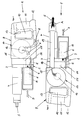
- the hand welding device shown in Figures 1 and 2 1 has as a central part a transmission 2 with a transmission housing 3 on.
- the transmission housing 3 consists of Metal and takes a gear set as well as a toothed belt transmission on.
- a plasticizer 4 flanged which is essentially a - stepped - has cylindrical shape.
- the plasticizing device 4 extends a passageway, in the usual way a screw conveyor is arranged.
- the wall of the passageway is from surrounded by a heating jacket, which is connected to an electric Resistance heating is provided and in operation for the Heating the through the passageway by means of the screw conveyor transported plastic material up to its plasticization ensures.
- the plastic material is in wire form over a feed opening, not shown here pulled into the plasticizer 4. During the welding process, this is transferred to the plasticiser 4 plasticized plastic material on the free, as Welding shoe 5 formed end ejected.
- a drive motor 6 in the form of an electric brushless permanent magnet motor flanged. Its output shaft 7 protrudes into the transmission 2.
- the transmission 2 transmits the rotational movement of the output shaft 7 upwards on the Screw conveyor in the plasticizer 4 and ensures there when switching on the drive motor 6 for the rotational movement.
- the drive motor 6 is on the outside of a surrounded cylindrical motor housing 8, also at the gearbox 2 is flanged and at the front Front has air inlet openings.
- the motor housing 8 has a free distance to the outside of the Plasticizing device 4.
- a handle housing 9 attached at the back of the gear housing 3 . It consists of a plastic molding, the top and bottom substantially straight is trained. In the rear area, the handle housing 9 a closed handle opening 10, the rear side is limited by a handle 11, the two sides is enclosed by the handle housing 9. The handle 11 has a projection at the rear in the lower area 12, which forms an additional hand support. In the area the handle opening 10 protrudes from the handle 11 Actuator button 13 in front, with a switch for input and Turning off the drive motor 6 is provided.
- a radial fan 14 Integrated in the handle housing 9, albeit on the right Side outward, is a radial fan 14. It has a fan housing 15 in which one of a Electric motor 16 driven impeller 17 is arranged is. The fan housing 15 is an integral part of the Handle housing 9.
- an air heater 19 which is parallel and at the same height to the plasticizer 4 to near the Welding shoe 5 runs and there in a free opening ends.
- the Luftetzrohr 19 is an air heater in Form of resistance heating built in, which from the Radial fan 14 and the outlet 18 outflowing air heats up and expels according to the arrow A.
- On the suction side 20 of the fan housing 15 is a square in cross-section Heatsink 21 attached, the one supply air duct forms for the radial fan 14.
- the heat sink 21 is made from a good thermal conductivity material, for example Aluminum.
- Of the two facing each other vertical insides are a variety of cooling fins - exemplified with 22 - before, which up to the proximity of the electric motor 16 range. In operation flows sucked by the radial fan 14 and accordingly in the heat sink 21 incoming air (see arrow B) the cooling fins 22 over and at the output 18 (see Arrow C) into the air heating tube 19 ( Figure 2).
- the Heat sink 21 On the two vertical sides and at the bottom of the Heat sink 21 are electronic components in the immediate Proximity to and / or disposed adjacent to the heat sink 21. These are above all such electronic components 23, which is in operation of the manual welder 1 warm up, such as the Power semiconductor for switching the heating elements of Plasticizing 4 and the heating element in Heil Kunststoffrohr 19, the temperature control electronics for these heating elements as well as the controller for the speed control of the Drive motor 6.
- the electronic components 23 are on PCB 24 mounted in the handle housing. 9 (see Figures 1 and 2) are fixed. In operation give the Electronic components 23 their heat to the heat sink 21st from. The passing on the cooling fins 22 intake air absorbs the heat. In this way, the electronic components 23 cooled and at the same time the intake air warmed up accordingly.
- the electric motor 16 protrudes into the Heat sink 21 into it, so that he from the intake air flows around and the heat generated by it to the intake air is dissipated.
- the handle housing 9 has one on the left side here not shown air inlet, on the outside additional intake air (arrow G) parallel to the intake air sucked into the heat sink 21 via the motor housing 8 and heated there.
- the handle housing 9 On the top of the handle housing 9 are - what here not shown in detail - more controls in the form of a membrane keyboard as well as displays for the display For example, admitted by temperatures and speed.
- the handling of the hand welder 1 happens in the Way that it with one hand to the motor housing. 8 is supported by the motor housing 8 gripped from below is, and with the other hand, the handle 11 comprises becomes. In this way, the hand welder is 1 precise and easy to handle. By the accommodation the electronic components 23 and the radial fan 14 in the handle housing 9, the hand welder 1 is extraordinary compact and leaves a clear view of the Welding point too.
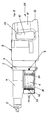
- FIG. 5 shows a hand welding device 31 in the left side view represented, whose parts, as far as they are concerned with Hand welder 1 according to Figures 1 and 2 agree, are provided with the same reference numerals. As description the parts provided with these reference numbers is related to the description of the manual welder 1 taken.
- the hand welder 31 differs from the manual welder 1 according to FIGS. 1 and 2 merely by that on the output side facing away from the front Side of the drive motor 6 to a Axialgebläserad 32 the forward protruding shaft 33 of the drive motor. 6 is attached and that the motor housing 8 in the area close of the transmission 2 air intake slots - exemplified by 34 designated - has.
- the axial fan wheel sucks 32 via the air intake slots 34 air, which then Cooling past the drive motor 6 and over at the front of the motor housing 8 existing Slits - in the hand welder 1 they serve as Air intake - is ejected.
- the motor housing 8 has no connection to the interior of the Grip housing 9 and thus to the radial fan 14th
- the axial fan 32 in reverse Direction promotes, so that air over the slots sucked on the front side of the motor housing 8 and over the slots 34 are ejected. It is also conceivable omit the air intake slots 34 and a connection to the interior of the handle housing 9 in the manner to create, as in the manual welder 1 according to the figures 1 and 2. In this case, the axial fan 32 would support the radial fan 14 and for an even more intense Cooling of the electric motor 6 worries.
Landscapes
- Engineering & Computer Science (AREA)
- Mechanical Engineering (AREA)
- Chemical & Material Sciences (AREA)
- Combustion & Propulsion (AREA)
- Health & Medical Sciences (AREA)
- Clinical Laboratory Science (AREA)
- Lining Or Joining Of Plastics Or The Like (AREA)
Abstract
Description
- Figur 1
- die linke Seitenansicht des erfindungsgemäßen Handschweißgerätes;
- Figur 2
- die rechte Seitenansicht des erfindungsgemäßen Handschweißgerätes nach Drehung der Ansicht gemäß Figur 1 um 180°;
- Figur 3
- das Gebläse für die Heißlufterzeugungseinrichtung mit Elektronikkomponente von der Saugseite her gesehen;
- Figur 4
- das Gebläse gemäß Figur 3 von der Druckseite her gesehen;
- Figur 5
- die Seitenansicht des Handschweißgerätes gemäß den Figuren 1 und 2 in modifizierter Ausführung.
Claims (23)
- Handschweißgerät (1, 31) zum Verschweißen von Kunststoffwerkstücken mittels plastifizierten Kunststoffmaterial, mit einer Fördereinrichtung zur Förderung des Kunststoffmaterials durch eine Plastifiziereinrichtung (4) zu einem Ausgang (5), wobei die Fördereinrichtung von einem elektrischen Antriebsmotor (6) über ein Getriebe (2) angetrieben ist, dadurch gekennzeichnet, daß der Antriebsmotor (6) innerhalb eines Motorgehäuses (8) unterhalb der Plastifiziereinrichtung (4) angeordnet ist.
- Handschweißgerät nach Anspruch 1, dadurch gekennzeichnet, daß das Motorgehäuse (8) keine direkte Berührung mit der Plastifiziereinrichtung (4) hat.
- Handschweißgerät nach Anspruch 1 oder 2, dadurch gekennzeichnet, daß das Motorgehäuse (8) wenigstens untenseitig gerundet ist.
- Handschweißgerät nach Anspruch 3, dadurch gekennzeichnet, daß das Motorgehäuse (8) zumindest halbzylindrische Formgebung hat.
- Handschweißgerät nach einem der Ansprüche 1 bis 4, dadurch gekennzeichnet, daß sich die Längsachse des Antriebsmotors (6) parallel zur Förderrichtung in der Plastifiziereinrichtung (4) erstreckt.
- Handschweißgerät nach einem der Ansprüche 1 bis 5, dadurch gekennzeichnet, daß das Motorgehäuse (8) außenseitig eine die Griffigkeit verbessernde Oberflächenstrukturierung und/oder -beschichtung aufweist.
- Handschweißgerät nach einem der Ansprüche 1 bis 6, dadurch gekennzeichnet, daß der Antriebsmotor (6) mit seinem rückwärtigen, abtriebsseitigen Ende an dem Getriebe (2) angeflanscht ist.
- Handschweißgerät nach einem der Ansprüche 1 bis 7, dadurch gekennzeichnet, daß das Getriebe (2) ein Getriebegehäuse (3) aufweist, an dessen Vorderseite die Plastifiziereinrichtung (4) und der Antriebsmotor (6) mit Motorgehäuse (8) und an dessen Rückseite ein Griffgehäuse (9) mit einem Handgriff (11) angebracht sind.
- Handschweißgerät nach Anspruch 8, dadurch gekennzeichnet, daß der Handgriff (11) an der Rückseite des Griffgehäuses (9) ausgebildet ist.
- Handschweißgerät nach Anspruch 9, dadurch gekennzeichnet, daß der Handgriff (11) oben- und untenseitig unter Bildung einer geschlossenen Grifföffnung (10) eingefaßt ist.
- Handschweißgerät nach Anspruch 10, dadurch gekennzeichnet, daß der Handgriff ein in die Grifföffnung (10) vorstehendes Schaltelement (13) für das Ein- und Ausschalten das Antriebsmotors (6) aufweist.
- Handschweißgerät nach einem der Ansprüche 8 bis 11, dadurch gekennzeichnet, daß in dem Griffgehäuse (9) Komponenten zur Steuerung und/oder Regelung des Handschweißgeräts (1, 31) angeordnet sind.
- Handschweißgerät nach einem der Ansprüche 8 bis 12, dadurch gekennzeichnet, daß das Griffgehäuse (9) eine Tastatur zur Bedienung des Handschweißgeräts (1, 31) aufweist.
- Handschweißgerät nach Anspruch 13, dadurch gekennzeichnet, daß die Tastatur an der Oberseite des Griffgehäuses (9) angeordnet ist.
- Handschweißgerät nach Anspruch 13 oder 14, dadurch gekennzeichnet, daß die Tastatur als Folientastatur ausgebildet ist.
- Handschweißgerät nach einem der Ansprüche 8 bis 15, dadurch gekennzeichnet, daß das Handschweißgerät (1, 31) eine Heißlufterzeugungseinrichtung (14, 19) mit einem Gebläse (14) aufweist, wobei das Gebläse (14) dem Griffgehäuse (9) zugeordnet ist.
- Handschweißgerät nach Anspruch 16, dadurch gekennzeichnet, daß das Gebläse als Radialgebläse (14) mit einer sich quer zur Längsachse des Handschweißgeräts (1, 31) erstreckenden Drehachse ausgebildet ist.
- Handschweißgerät nach Anspruch 16 oder 17, dadurch gekennzeichnet, daß das Gebläse (14) mit seiner Saugseite Verbindung zum Innenraum des Motorgehäuses (8) hat und das Motorgehäuse derart mit Lufteinlaßöffnungen versehen ist, daß Ansaugluft für das Gebläse (14) an dem Antriebsmotor (6) vorbeiströmt.
- Handschweißgerät nach Anspruch 18, dadurch gekennzeichnet, daß die Ansaugluft das Getriebe (2) durchsetzt.
- Handschweißgerät nach wenigsten den Ansprüchen 12 und 16, dadurch gekennzeichnet, daß die Komponenten (23) an einem Kühlkörper (21) angeordnet sind, der im Betrieb von Ansaugluft des Gebläses (14) durchströmt ist.
- Handschweißgerät nach einem der Ansprüche 17 bis 20, dadurch gekennzeichnet, daß das Gebläse (14) ein Gebläsegehäuse (15) aufweist, das von dem Griffgehäuse (9) gebildet ist.
- Handschweißgerät nach einem der Ansprüche 1 bis 21, dadurch gekennzeichnet, daß das Getriebe (2) einen Zahnriementrieb aufweist.
- Handschweißgerät nach einem der Ansprüche 1 bis 22, dadurch gekennzeichnet, daß der Antriebsmotor (6) als bürstenloser Permanentmagnetmotor ausgebildet ist, der über einen Regler drehzahlgesteuert ist.
Priority Applications (1)
| Application Number | Priority Date | Filing Date | Title |
|---|---|---|---|
| DE200520003919 DE202005003919U1 (de) | 2004-03-15 | 2005-03-09 | Handschweißgerät zum Verschweißen von Kunststoffwerkstücken |
Applications Claiming Priority (4)
| Application Number | Priority Date | Filing Date | Title |
|---|---|---|---|
| DE202004004147U DE202004004147U1 (de) | 2004-03-15 | 2004-03-15 | Vorrichtung zur Ableitung der Abwärme, die durch die Verwendung von Leistungshalbleitern in Kunststoff-Schweißextrudern zum direkten Anschluss an das Wechselstrom- oder Drehstromnetz entsteht |
| DE202004004147U | 2004-03-15 | ||
| DE202004006405 | 2004-04-20 | ||
| DE202004006405U | 2004-04-20 |
Publications (3)
| Publication Number | Publication Date |
|---|---|
| EP1577079A2 true EP1577079A2 (de) | 2005-09-21 |
| EP1577079A3 EP1577079A3 (de) | 2008-01-23 |
| EP1577079B1 EP1577079B1 (de) | 2009-04-29 |
Family
ID=34839630
Family Applications (2)
| Application Number | Title | Priority Date | Filing Date |
|---|---|---|---|
| EP04024835A Expired - Lifetime EP1577079B1 (de) | 2004-03-15 | 2004-10-19 | Handschweissgerät zum Verschweissen von Kunststoffwerkstücken |
| EP04024834A Expired - Lifetime EP1577078B1 (de) | 2004-03-15 | 2004-10-19 | Handschweissgerät zum Verschweissen von Kunststoffwerkstücken |
Family Applications After (1)
| Application Number | Title | Priority Date | Filing Date |
|---|---|---|---|
| EP04024834A Expired - Lifetime EP1577078B1 (de) | 2004-03-15 | 2004-10-19 | Handschweissgerät zum Verschweissen von Kunststoffwerkstücken |
Country Status (3)
| Country | Link |
|---|---|
| EP (2) | EP1577079B1 (de) |
| AT (2) | ATE430017T1 (de) |
| DE (2) | DE502004009412D1 (de) |
Cited By (1)
| Publication number | Priority date | Publication date | Assignee | Title |
|---|---|---|---|---|
| EP1637234B2 (de) † | 2004-09-08 | 2012-06-13 | Leister Technologies AG | Handextruderschweissgerät |
Families Citing this family (1)
| Publication number | Priority date | Publication date | Assignee | Title |
|---|---|---|---|---|
| CN206099752U (zh) * | 2016-06-01 | 2017-04-12 | 浙江普莱得电器有限公司 | 设有控制电路的无刷热风枪 |
Family Cites Families (13)
| Publication number | Priority date | Publication date | Assignee | Title |
|---|---|---|---|---|
| FR1316252A (fr) * | 1962-02-27 | 1963-01-25 | Amut Spa | Limiteur d'efforts particulièrement apte à éviter des dommages aux extrudeurs de matières plastiques par suite des surcharges |
| US3314574A (en) * | 1965-08-11 | 1967-04-18 | United Shoe Machinery Corp | Plastic cement heating, melting and extruding tool |
| DE1629748A1 (de) * | 1967-06-02 | 1971-03-11 | Demag Ag | Kunststoff-Schneckenpresse |
| US3750905A (en) * | 1972-08-23 | 1973-08-07 | Hardman Inc | Hand-held extruding apparatus |
| JPS51123271A (en) * | 1975-04-18 | 1976-10-27 | Purasuchitsuku Kougaku Kenkiyu | Synthetic resin extruder |
| JPS5522364A (en) * | 1978-08-07 | 1980-02-18 | Wakita Seisakusho:Kk | Portable sealant heating extruder |
| DE3341201A1 (de) * | 1983-11-14 | 1985-05-30 | Reinhard 8088 Eching Ursprung | Klebepistole |
| DE3833677C1 (de) * | 1988-10-04 | 1989-07-27 | Zinser-Schweisstechnik Gmbh & Co, 7333 Ebersbach, De | |
| DE4119137C1 (en) * | 1991-06-11 | 1993-02-25 | Munsch Chemie-Pumpen Gmbh, 5412 Ransbach-Baumbach, De | Welding appts. for thermoplastic material - includes heatable advancing chamber, drive for an advancing element and air heater for pre-warmed air |
| US5244123A (en) * | 1991-10-28 | 1993-09-14 | Flora M. Benedict | Apparatus and method for applying sealing material |
| DE20110173U1 (de) * | 2001-06-19 | 2001-09-13 | Munsch Kunststoff-Schweißtechnik GmbH, 56235 Ransbach-Baumbach | Extruder-Handschweißgerät |
| US6585135B1 (en) * | 2002-01-18 | 2003-07-01 | Kuo-Chung Yeh | Anti-reverse structure of a continuous pneumatic oil feeding gun |
| US6558059B1 (en) * | 2002-02-20 | 2003-05-06 | George Hillinger | Glue gun with pinch rollers |
-
2004
- 2004-10-19 EP EP04024835A patent/EP1577079B1/de not_active Expired - Lifetime
- 2004-10-19 AT AT04024835T patent/ATE430017T1/de active
- 2004-10-19 DE DE502004009412T patent/DE502004009412D1/de not_active Expired - Lifetime
- 2004-10-19 DE DE502004009413T patent/DE502004009413D1/de not_active Expired - Lifetime
- 2004-10-19 EP EP04024834A patent/EP1577078B1/de not_active Expired - Lifetime
- 2004-10-19 AT AT04024834T patent/ATE430016T1/de active
Cited By (1)
| Publication number | Priority date | Publication date | Assignee | Title |
|---|---|---|---|---|
| EP1637234B2 (de) † | 2004-09-08 | 2012-06-13 | Leister Technologies AG | Handextruderschweissgerät |
Also Published As
| Publication number | Publication date |
|---|---|
| EP1577078A2 (de) | 2005-09-21 |
| ATE430016T1 (de) | 2009-05-15 |
| EP1577079B1 (de) | 2009-04-29 |
| EP1577078A3 (de) | 2008-01-23 |
| DE502004009412D1 (de) | 2009-06-10 |
| ATE430017T1 (de) | 2009-05-15 |
| EP1577078B1 (de) | 2009-04-29 |
| EP1577079A3 (de) | 2008-01-23 |
| DE502004009413D1 (de) | 2009-06-10 |
Similar Documents
| Publication | Publication Date | Title |
|---|---|---|
| EP1637234B2 (de) | Handextruderschweissgerät | |
| EP2155465B1 (de) | Extruderschweisseinrichtung | |
| DE4238564C2 (de) | Elektrowerkzeug | |
| DE102008060703B4 (de) | Angetriebenes Werkzeug | |
| EP0794038A2 (de) | Handwerkzeug mit Anordnung zum Kühlen | |
| EP1475052B1 (de) | Lichtpolymerisationsgerät mit Gebläse | |
| DE102005007545B4 (de) | Vorrichtung und Verfahren zur Kühlung einer Elektronik | |
| DE29915768U1 (de) | Extruderschweißeinrichtung | |
| DE19600339C1 (de) | Handwerkzeug | |
| DE2331966A1 (de) | Naehmaschine | |
| DE3783953T2 (de) | Vorrichtung zur temperaturregelung von extrudier-spritzgiess- und -ziehmaschinen und -zylinder fuer kunststoffe. | |
| WO2006072489A1 (de) | Elektrohandwerkzeugmaschine | |
| EP1634689A1 (de) | Handextruderschweissgerät | |
| EP1577079B1 (de) | Handschweissgerät zum Verschweissen von Kunststoffwerkstücken | |
| DE202010006044U1 (de) | Wassergekühlte Papierzerkleinerungsvorrichtung | |
| DE202005003919U1 (de) | Handschweißgerät zum Verschweißen von Kunststoffwerkstücken | |
| DE4330878A1 (de) | Heizlüfter | |
| DE202005003920U1 (de) | Handschweißgerät zum Verschweißen von Kunststoffwerkstücken | |
| EP0594889A1 (de) | Schweissgerät | |
| DE4119137C1 (en) | Welding appts. for thermoplastic material - includes heatable advancing chamber, drive for an advancing element and air heater for pre-warmed air | |
| DE202014100647U1 (de) | Heißluftgerät | |
| EP2392445A2 (de) | Handschweißgerät | |
| DE10230473B4 (de) | Tor für Ballspiele | |
| DE19952166A1 (de) | Schweißgerät für thermoplastische Kunststoffe | |
| DE202007014873U1 (de) | Kunststoffschweißgerät zum Verschweißen von Werkstücken aus Kunststoff |
Legal Events
| Date | Code | Title | Description |
|---|---|---|---|
| PUAI | Public reference made under article 153(3) epc to a published international application that has entered the european phase |
Free format text: ORIGINAL CODE: 0009012 |
|
| AK | Designated contracting states |
Kind code of ref document: A2 Designated state(s): AT BE BG CH CY CZ DE DK EE ES FI FR GB GR HU IE IT LI LU MC NL PL PT RO SE SI SK TR |
|
| AX | Request for extension of the european patent |
Extension state: AL HR LT LV MK |
|
| PUAL | Search report despatched |
Free format text: ORIGINAL CODE: 0009013 |
|
| AK | Designated contracting states |
Kind code of ref document: A3 Designated state(s): AT BE BG CH CY CZ DE DK EE ES FI FR GB GR HU IE IT LI LU MC NL PL PT RO SE SI SK TR |
|
| AX | Request for extension of the european patent |
Extension state: AL HR LT LV MK |
|
| 17P | Request for examination filed |
Effective date: 20080623 |
|
| AKX | Designation fees paid |
Designated state(s): AT CH DE IT LI |
|
| GRAP | Despatch of communication of intention to grant a patent |
Free format text: ORIGINAL CODE: EPIDOSNIGR1 |
|
| RAP1 | Party data changed (applicant data changed or rights of an application transferred) |
Owner name: WEGENER INTERNATIONAL GMBH |
|
| GRAS | Grant fee paid |
Free format text: ORIGINAL CODE: EPIDOSNIGR3 |
|
| GRAA | (expected) grant |
Free format text: ORIGINAL CODE: 0009210 |
|
| AK | Designated contracting states |
Kind code of ref document: B1 Designated state(s): AT CH DE IT LI |
|
| REG | Reference to a national code |
Ref country code: CH Ref legal event code: EP |
|
| REF | Corresponds to: |
Ref document number: 502004009413 Country of ref document: DE Date of ref document: 20090610 Kind code of ref document: P |
|
| PLBE | No opposition filed within time limit |
Free format text: ORIGINAL CODE: 0009261 |
|
| STAA | Information on the status of an ep patent application or granted ep patent |
Free format text: STATUS: NO OPPOSITION FILED WITHIN TIME LIMIT |
|
| 26N | No opposition filed |
Effective date: 20100201 |
|
| PGFP | Annual fee paid to national office [announced via postgrant information from national office to epo] |
Ref country code: AT Payment date: 20121001 Year of fee payment: 9 |
|
| REG | Reference to a national code |
Ref country code: AT Ref legal event code: MM01 Ref document number: 430017 Country of ref document: AT Kind code of ref document: T Effective date: 20131019 |
|
| PG25 | Lapsed in a contracting state [announced via postgrant information from national office to epo] |
Ref country code: AT Free format text: LAPSE BECAUSE OF NON-PAYMENT OF DUE FEES Effective date: 20131019 |
|
| P01 | Opt-out of the competence of the unified patent court (upc) registered |
Effective date: 20230404 |
|
| P02 | Opt-out of the competence of the unified patent court (upc) changed |
Effective date: 20230508 |
|
| PGFP | Annual fee paid to national office [announced via postgrant information from national office to epo] |
Ref country code: IT Payment date: 20231031 Year of fee payment: 20 Ref country code: DE Payment date: 20230918 Year of fee payment: 20 Ref country code: CH Payment date: 20231102 Year of fee payment: 20 |
|
| REG | Reference to a national code |
Ref country code: DE Ref legal event code: R071 Ref document number: 502004009413 Country of ref document: DE |
|
| REG | Reference to a national code |
Ref country code: CH Ref legal event code: PL |