EP1577180B1 - Diebstahlsicherung - Google Patents
Diebstahlsicherung Download PDFInfo
- Publication number
- EP1577180B1 EP1577180B1 EP03780781.5A EP03780781A EP1577180B1 EP 1577180 B1 EP1577180 B1 EP 1577180B1 EP 03780781 A EP03780781 A EP 03780781A EP 1577180 B1 EP1577180 B1 EP 1577180B1
- Authority
- EP
- European Patent Office
- Prior art keywords
- transmission
- power
- reception
- feeding
- signal
- Prior art date
- Legal status (The legal status is an assumption and is not a legal conclusion. Google has not performed a legal analysis and makes no representation as to the accuracy of the status listed.)
- Expired - Lifetime
Links
Images



Classifications
-
- B—PERFORMING OPERATIONS; TRANSPORTING
- B60—VEHICLES IN GENERAL
- B60R—VEHICLES, VEHICLE FITTINGS, OR VEHICLE PARTS, NOT OTHERWISE PROVIDED FOR
- B60R25/00—Fittings or systems for preventing or indicating unauthorised use or theft of vehicles
- B60R25/01—Fittings or systems for preventing or indicating unauthorised use or theft of vehicles operating on vehicle systems or fittings, e.g. on doors, seats or windscreens
- B60R25/04—Fittings or systems for preventing or indicating unauthorised use or theft of vehicles operating on vehicle systems or fittings, e.g. on doors, seats or windscreens operating on the propulsion system, e.g. engine or drive motor
- B60R25/045—Fittings or systems for preventing or indicating unauthorised use or theft of vehicles operating on vehicle systems or fittings, e.g. on doors, seats or windscreens operating on the propulsion system, e.g. engine or drive motor by limiting or cutting the electrical supply to the propulsion unit
-
- G—PHYSICS
- G08—SIGNALLING
- G08G—TRAFFIC CONTROL SYSTEMS
- G08G1/00—Traffic control systems for road vehicles
- G08G1/20—Monitoring the location of vehicles belonging to a group, e.g. fleet of vehicles, countable or determined number of vehicles
- G08G1/205—Indicating the location of the monitored vehicles as destination, e.g. accidents, stolen, rental
-
- B—PERFORMING OPERATIONS; TRANSPORTING
- B60—VEHICLES IN GENERAL
- B60R—VEHICLES, VEHICLE FITTINGS, OR VEHICLE PARTS, NOT OTHERWISE PROVIDED FOR
- B60R16/00—Electric or fluid circuits specially adapted for vehicles and not otherwise provided for; Arrangement of elements of electric or fluid circuits specially adapted for vehicles and not otherwise provided for
- B60R16/02—Electric or fluid circuits specially adapted for vehicles and not otherwise provided for; Arrangement of elements of electric or fluid circuits specially adapted for vehicles and not otherwise provided for electric constitutive elements
- B60R16/03—Electric or fluid circuits specially adapted for vehicles and not otherwise provided for; Arrangement of elements of electric or fluid circuits specially adapted for vehicles and not otherwise provided for electric constitutive elements for supply of electrical power to vehicle subsystems or for
-
- B—PERFORMING OPERATIONS; TRANSPORTING
- B60—VEHICLES IN GENERAL
- B60R—VEHICLES, VEHICLE FITTINGS, OR VEHICLE PARTS, NOT OTHERWISE PROVIDED FOR
- B60R25/00—Fittings or systems for preventing or indicating unauthorised use or theft of vehicles
- B60R25/01—Fittings or systems for preventing or indicating unauthorised use or theft of vehicles operating on vehicle systems or fittings, e.g. on doors, seats or windscreens
- B60R25/04—Fittings or systems for preventing or indicating unauthorised use or theft of vehicles operating on vehicle systems or fittings, e.g. on doors, seats or windscreens operating on the propulsion system, e.g. engine or drive motor
-
- B—PERFORMING OPERATIONS; TRANSPORTING
- B60—VEHICLES IN GENERAL
- B60R—VEHICLES, VEHICLE FITTINGS, OR VEHICLE PARTS, NOT OTHERWISE PROVIDED FOR
- B60R25/00—Fittings or systems for preventing or indicating unauthorised use or theft of vehicles
- B60R25/10—Fittings or systems for preventing or indicating unauthorised use or theft of vehicles actuating a signalling device
- B60R25/102—Fittings or systems for preventing or indicating unauthorised use or theft of vehicles actuating a signalling device a signal being sent to a remote location, e.g. a radio signal being transmitted to a police station, a security company or the owner
-
- B—PERFORMING OPERATIONS; TRANSPORTING
- B60—VEHICLES IN GENERAL
- B60R—VEHICLES, VEHICLE FITTINGS, OR VEHICLE PARTS, NOT OTHERWISE PROVIDED FOR
- B60R25/00—Fittings or systems for preventing or indicating unauthorised use or theft of vehicles
- B60R25/30—Detection related to theft or to other events relevant to anti-theft systems
- B60R25/33—Detection related to theft or to other events relevant to anti-theft systems of global position, e.g. by providing GPS coordinates
-
- G—PHYSICS
- G08—SIGNALLING
- G08B—SIGNALLING SYSTEMS, e.g. PERSONAL CALLING SYSTEMS; ORDER TELEGRAPHS; ALARM SYSTEMS
- G08B13/00—Burglar, theft or intruder alarms
- G08B13/02—Mechanical actuation
- G08B13/14—Mechanical actuation by lifting or attempted removal of hand-portable articles
- G08B13/1409—Mechanical actuation by lifting or attempted removal of hand-portable articles for removal detection of electrical appliances by detecting their physical disconnection from an electrical system, e.g. using a switch incorporated in the plug connector
-
- B—PERFORMING OPERATIONS; TRANSPORTING
- B60—VEHICLES IN GENERAL
- B60W—CONJOINT CONTROL OF VEHICLE SUB-UNITS OF DIFFERENT TYPE OR DIFFERENT FUNCTION; CONTROL SYSTEMS SPECIALLY ADAPTED FOR HYBRID VEHICLES; ROAD VEHICLE DRIVE CONTROL SYSTEMS FOR PURPOSES NOT RELATED TO THE CONTROL OF A PARTICULAR SUB-UNIT
- B60W2556/00—Input parameters relating to data
- B60W2556/45—External transmission of data to or from the vehicle
- B60W2556/50—External transmission of data to or from the vehicle of positioning data, e.g. GPS [Global Positioning System] data
Definitions
- This invention relates to an antitheft system, which is arranged on a self-propelling movable object including a construction machine such as a hydraulic excavator and makes it possible to ascertain the position of the movable object on the side of a control server located at a place remote from the movable object.
- the German patent publication DE 197 33 579 discloses a motor vehicle monitoring method.
- the method involves transmitting position data from a mobile unit in the motor vehicle to a remote control centre via a radio transmission network.
- the position data are determined by a satellite navigation system.
- the mobile unit comprises an internal power source and connection means for an external power source.
- JP 2000-73411 A a technology that detects, for example, by a global positioning system, i.e., GPS the position of a hydraulic excavator as a self-propelling movable object under control, transmits by wireless communication the thus-detected position of the hydraulic excavator to a control server located at a remote place, and ascertains by the control server whether or not the position of the hydraulic excavator is within a predetermined normal work area.
- a global positioning system i.e., GPS the position of a hydraulic excavator as a self-propelling movable object under control
- an engine stop signal is transmitted from the control server to a control system mounted on the hydraulic excavator to stop an operation of the hydraulic excavator.
- the conventional technology makes it possible to promptly infer the theft of the hydraulic excavator and to disable work such as digging or running by the hydraulic excavator and, because the hydraulic excavator becomes no longer possible of self-propelling, also makes it difficult to load the hydraulic excavator on a vehicle for carrying it away, for example, a trailer. Accordingly, the conventional technology can scare away a potential thief and practically, can make it difficult to steal, thereby serving as an effective technology for the prevention of a theft.
- a first object of the present invention is, therefore, to provide an antitheft system which can ascertain the position of a movable object even during stopping of an engine while reducing the consumption of power by a control system during the stopping of the engine and avoiding a battery drainage.
- a second obj ect of the present invention is to provide an antitheft system which cankeep the communication cost lowbyminimizing the number of communications with a control server.
- the present invention provides an antitheft system according to claim 1.
- the current position of the movable object can be detected by the position detecting means in a similar manner as in the time of an operation of the engine until the first predetermined time elapses from a time point at which the engine is stopped. After the elapse of the first predetermined time, the feeding of power by the first power feeding means is stopped so that the feeding of power to the position detecting means is stopped. To the clocking means, however, power is continuously fed from the second power feeding means. Based on signals from the clocking means, power is fed at the predetermined time intervals from the first power feeding means to the position detecting means so that a positional detection is performed intermittently. Namely, power is intermittently fed from the first power feeding means to the position detecting means after the elapse of the first predetermined time. The consumption of power at the position detectingmeans can, therefore, be cut down as much as the stopping of power feeding.
- the invention described in claim 5 to achieve the second object is characterized in that the control system is provided with a storage means for storing the position information on the movable object as detected by the position detecting means, and the processing means compares position information, which has been detected subsequent to the input of the stop signal for the engine, with the position information stored in the storage means and, when a distance difference of at least a predetermined value is confirmed, determines that the movable object has been stolen, and instructs the transmission/receptionmeans to transmit a theft signal together with the position information to the control server.
- the present invention can detect the current position of the movable object by the position detecting means in a similar manner as in the time of an operation of the engine until the first predetermined time elapses from a time point at which the engine is stopped, and after the elapse of the first predetermined time, can feed power at the predetermined time intervals from the first power feeding means to the position detecting means so that a positional detection can be performed intermittently.
- power is intermittently fed from the first power feeding means to the position detecting means after the elapse of the first predetermined time.
- the consumption of power at the position detectingmeans can, therefore, be cut down as much as the stopping of power feeding. Accordingly, it is possible to prolong the time until the battery mounted on the movable object comes into the state of a battery drainage.
- whether or not the movable object has been stolen can be determined by the control system mounted on the movable object and, only when a theft has been determined, a report is made to the side of the control server via the transmission/reception means. Accordingly, the number of communications with the control server can be reduced so that the communication cost can be kept low.
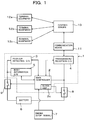
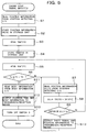
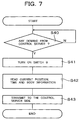
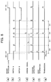
- FIG. 1 through FIG. 8 are drawings for describing the first embodiment of the present invention, in which FIG. 1 is an overall construction diagram of an antitheft system according to the first embodiment of the present invention, FIG. 2 is a block diagram of a main controller constructing the antitheft system shown in FIG. 1 , FIG. 3 is a block diagram of a position detecting control unit, FIG. 4 is a block diagram of a body information control unit, FIG. 5 is a flow chart of processing operations until a first predetermined time Ts elapses since the input of an engine stop signal, FIG. 6 is a flow chart of processing operations after Ts has elapsed subsequent to the stopping of the engine, FIG. 7 is a flow chart of processing when an information demand signal has been inputted from a control server, and FIG. 8 is a time chart after the engine stop signal has been inputted.
- the antitheft system is provided with a control system 1 to be mounted on a self-propelling movable object, for example, a hydraulic excavator with an engine 7 mounted as a drive source thereon and also with a control server 10 for performing transmissions/receptions of information with the control system 1, which is located at a remote plate, via a wireless communication means 11 such as satellite communication or telephone line communication and also for managing a control of information on the hydraulic excavator.
- a control system 1 to be mounted on a self-propelling movable object, for example, a hydraulic excavator with an engine 7 mounted as a drive source thereon and also with a control server 10 for performing transmissions/receptions of information with the control system 1, which is located at a remote plate, via a wireless communication means 11 such as satellite communication or telephone line communication and also for managing a control of information on the hydraulic excavator.
- the control system 1 is provided with a position detecting control unit 3 for detecting the position of the hydraulic excavator by GPS, a body information control unit 5 for fetching signals from various sensors arranged on the hydraulic excavator and detecting and storing various information on operations of the hydraulic excavator, a transmission/reception control unit 4 for performing transmissions/receptions of information with the control server 10, and a main controller 2 for controlling the respective control units 3,4,5 systematically and performing predetermined processing operations.
- a position detecting control unit 3 for detecting the position of the hydraulic excavator by GPS
- a body information control unit 5 for fetching signals from various sensors arranged on the hydraulic excavator and detecting and storing various information on operations of the hydraulic excavator
- a transmission/reception control unit 4 for performing transmissions/receptions of information with the control server 10
- a main controller 2 for controlling the respective control units 3,4,5 systematically and performing predetermined processing operations.
- the position detecting control unit 3 and body information control unit 5 are connected to the battery 6 via a switch 9 as a first power feeding means, while the main controller 2 and transmission/reception control unit 4 are connected to the battery 6 via a switch 8 as a second power feeding means.
- terminal equipment 12a, 12b, 12c are connected via a network to permit an access by the owner, maker, service mechanic or the like of the hydraulic excavator to the control server 10 for the confirmation of an operation state of the hydraulic excavator.
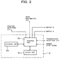
- the main controller 2 is provided, as shown in FIG. 2 , with a control unit 2a comprising a CPU to control the above-mentioned, respective control units 3,4,5, switch 8 and switch 9 systematically and to perform predetermined processing operations, a storage unit 2b for storing processing results temporarily in the course of processing operations and also storing various parameters and the like, and a clock unit 2c as a clocking means.
- a control unit 2a comprising a CPU to control the above-mentioned, respective control units 3,4,5, switch 8 and switch 9 systematically and to perform predetermined processing operations
- a storage unit 2b for storing processing results temporarily in the course of processing operations and also storing various parameters and the like
- a clock unit 2c as a clocking means.
- signals relating to an operation or stop of the engine 7 are also inputted.
- the position detecting control unit 3 is provided, as shown in FIG. 3 , a position detecting control unit 3c for capturing signals from unillustrated GPS satellites and calculating the position of the hydraulic excavator, a storage unit 3b for storing the thus-detected position information and a preset operable area for the hydraulic excavator, and a control unit 3a for performing transmissions/receptions of signals with the main controller 2, reading results of a detection by the position detecting unit 3c, andperformingprocessing to store the results of the detection in the storage unit 3b.
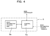
- the body information control unit 5 is provided, as shown in FIG. 4 , with a control unit 5a for performing transmissions/receptions of signals with the main controller 2 and fetching information from the unillustrated various sensors mounted on the hydraulic excavator, and a storage unit 5b for storing the information fetched from the sensors.
- the switch 8 and switch 9 always maintain their turned-on positions so that power is fed to the respective control units 3,4,5 and the main controller 2.
- the position detecting unit 3c which constructs the position detecting control unit 3, no matter whether or not there is an instruction signal from the control unit 3a, calculates the current position of the hydraulic excavator from signals from the GPS satellites upon capturing the signals, and outputs the results to the control unit 3a.
- the control unit 3a compares the inputted current position with the operable area stored in the storage unit 3b and, when the current position departs from the operable area, outputs information on the current position and a theft signal to the main controller 2.
- position information calculated based on processing at the control unit 3a is stored in the storage unit 3b.
- This instruction signal from the main controller 2 is designed such that it is inputted at preset time intervals, for example, every hour. It is, however, also possible to store such position information whenever calculated, without relying upon instructions from the main controller 2.
- the body information control unit 5 progressively stores signals, which are fed in predetermined sampling cycles from the various sensors, in time sequence in the storage unit 5b via the control unit 5a.
- the abnormality signal is immediately outputted to the main controller 2.
- the main controller 2 When the theft signal has been inputted from the position detecting control unit 3 or the abnormality signal has been inputted from the body information control unit 5, the main controller 2 outputs an instruction signal to the transmission/reception control unit 4 to transmit the signal to the control server 10.
- the main controller 2 instructs to send the position information and body information, which are stored in the position detecting control unit 3 and body information control unit 5, respectively, to the main controller 2, inputs these information, and outputs an instruction signal to the transmission/reception control unit 4 such that they are transmitted to the control server 10.
- the transmission/reception control unit 4 transmits the position information, theft signal, body information, abnormality information or the like to the control server 10 via the communication means 11.
- the main controller 2 reads in the first Step S1 the latest position information stored in the storage unit 3b of the position detection control unit 3, and in the next Step S2, stores the thus-read position information (X0, Y0) in the storage unit 2b of the main controller 2.
- the time T0 at which the stop signal of the engine 7 was inputted is read from the clock unit 2c in the next Step S3, and is stored in the storage unit 2b in Step S4.
- Step S5 a current time T1 is read from the clock unit 2b, and in the next Step S6, a determination is made as to whether or not a predetermined time Ts, for example, 3 hours or so have elapsed from the input of the stop signal of the engine 7. If not determined to have elapsed, the routine moves to Step S7.
- a predetermined time Ts for example, 3 hours or so have elapsed from the input of the stop signal of the engine 7. If not determined to have elapsed, the routine moves to Step S7.
- Step S7 current position information (X1, Y1) is read from the position detecting control unit 3, and in the next Step S8, the distance ⁇ L from the position (X0, Y0) at the time point of the input of the stop signal of the engine 7 is calculated. It is then determined in the next Step S9 whether or not the thus-calculated distance ⁇ L is greater than a predetermined distance Ls. When the distance ⁇ L is determined to be smaller than the predetermined distance Ls in Step S9, the hydraulic excavator is not determined to have been stolen, the routine returns to Step S5 and the processing operations of Steps S5 to S9 are repeated.
- Step S10 When the thus-calculated distance ⁇ L is determined to be equal to or greater than the predetermined distance Ls in Step S9, the routine moves to Step S10. After an instruction signal is outputted to the transmission/reception control unit 4 such that a theft signal and the position information (X1, Y1) at that time are transmitted to the control server 10, the routine returns to Step S7 and the processing operations of Step S7 to Step S10 are repeatedly performed.
- Step S11 When the predetermined time Ts is determined to have elapsed after the input of the stop signal of the engine 7 in Step S6, the routine moves to Step S11, and the body information stored in the storage unit 5b of the body information control unit 5 is read and is once stored in the storage unit 2b.
- Step S12 an instruction signal is outputted to the transmission/reception control unit 4 such that the stored body information, current time T1 and position information (X1, Y1) are transmitted to the control server 10.
- Step S13 a turn-off signal is outputted to the switch 9 so that the feeding of power to the position detecting control unit 3 and body information control unit 5 is cut off.
- the switch 9 retains its turned-on position until the predetermined time Ts elapses after the input of the stop signal from the engine 7. During this period, it is possible to ascertain whether or not the hydraulic excavator has been stolen in a similar manner as in the time of an operation of the engine. When determined to have been stolen, a report can be immediately made to the control server 10 located at the remote place.
- the switch retains its turned-on position even after the predetermined time Ts has elapsed subsequent to the input of the stop signal from the engine 7. Power is, therefore, still continuously fed from the battery 6 to the main controller 2 and transmission/reception control unit 4.
- a variable N for counting is set at 0, and in the next Step S21, the current time T2 is read from the clock unit 2c.
- Step S22 a determination is made as to whether or not a predetermined time interval ⁇ T has elapsed from the time of the preceding processing.
- ⁇ T is not determined to have elapsed
- the routine returns to Step S21.
- ⁇ T is determined to have elapsed
- the routine advances to the next Step S23.
- Step S23 an instruction signal is outputted to turn on the switch which has been in the turned-off position.
- power is fed to the position detecting control unit 3, and at the position detecting control unit 3, the position is detected and the current position information (X1, Y1) is outputted to the main controller 2.
- Step S24 the thus-outputted current position information (X1, Y1) is read, and in the next Step S25, the distance ⁇ L from the position (X0, Y0) at which the stop signal of the engine 7 was inputted is calculated.
- Step S26 a determination is made as to whether or not the thus-calculated distance ⁇ L is greater than the predetermined distance Ls. When determined to be smaller, the routine moves to Step S27.
- Step S27 1 is added to the variable N, and in the next Step S28, a signal is outputted to turn off the switch 9. As a result, the feeding of power to the position detecting control unit 3 is cut off.
- Step S29 a determination is made as to whether or not the processing operations from Steps S21 to S27 have reached a predetermined number of times N0. When N0 has not been reached yet, the routine is returned to Step S21.
- Step S25 When the distance ⁇ L calculated in Step S25 is determined to be greater than the predetermined distance Ls in Step S26, the routine moves to Step S32, and an instruction signal is outputted to the transmission/reception control unit 4 such that a theft signal and the position information (X1, Y1) at that time are transmitted to the control server 10.
- this instruction signal When this instruction signal is inputted, the transmission/reception control unit 4 transmits the current position information (X1, Y1) together with the theft signal to the control server 10.
- Step S30 When the number of processing operations, N, is determined to have reached N0 in Step S29, on the other hand, the routine moves to Step S30, and an instruction signal is outputted to the transmission/reception control unit 4 such that a signal to the effect that the transmission/reception processing is to end is transmitted together with the current position information (X1, Y1) to the control server 10.
- this indication signal is inputted, the transmission/reception control unit transmits a signal, which informs the control server 10 to the effect that the transmission/reception processing has ended, together with the current position information (X1, Y1) to the control server 10.
- Step S31 a turn-off signal is outputted to the switch S8.
- the feeding of power to the main controller 2 and transmission/reception control unit 4 is cut off so that at the control system 1, processing operations and transmissions/receptions with the outside are disabled.
- Step S42 the current position information is read from the position detecting control unit 3, and further, body information is read from the body information control unit 5 and the current time is also read from the clock unit 2c.
- an instruction signal is outputted to the transmission/reception control unit 4 such that they are transmitted to the control server 10.
- the transmission/reception control unit 4 transmits the position information and body information together with the current time to the control server 10.
- FIG. 8 is a time chart which shows in time sequence the processing operations in FIG. 5 to FIG. 7 .
- the switch 9 and switch 8 continuously retain their turned-on positions until the first predetermined time Ts elapses subsequent to the input of a stop signal (key off) of the engine 7((b), (c)), and after an elapse of Ts, the position information and body information on the hydraulic excavator are transmitted to the control server ((e), (f), (g)), and the switch 9 is turned off ((b)).
- the turn-on and turn-off of the switch 9 are repeated at the predetermined time intervals ⁇ t ((b)) and, whenever the switch 9 is brought into its turned-on position, the detection of a position at that time point is performed ((e)).
- the predetermined time intervals ⁇ t reach a predetermined number of times N0 (4 times in FIG. 8 )
- the position information and a signal that indicates the end of the transmission/reception processing are fed to the control server 10 ((g)), and the switch 8 and switch 9 are brought into their cut-off positions ((b),(c)).
- power is, therefore, intermittently transmitted from the battery 6 to the position detecting control unit 3 and body information control unit 5 via the switch 9 after the first predetermined time Ts has elapsed subsequent to a stop of the engine 7. It is, accordingly, possible to cut down the consumption of as much power at the position detecting control unit 3 and body information control unit 5 as the stop of the feeding of power. As a consequence, it is possible to prolong the time until the battery mounted on the hydraulic excavator comes into the state of a battery drainage.
- control system 1 mounted on the hydraulic excavator, it is also possible to determine despite the stopping of the engine 7 whether or not the hydraulic excavator has been moved, in other words, stolen. Because a report is made to the side of the control server 10 via the transmission/reception control unit 4 only when the hydraulic excavator is determined to have been stolen, the number of communications with the control server 10 can be reduced so that the communication cost can be kept low.
- the above-described first embodiment is designed such that, after the predetermined time Ts has elapsed subsequent to the input of the stop signal of the engine 7, the switch 9 is intermittently turned on and off only the predetermined number of times N0 at predetermined time intervals ⁇ t and a positional detection is performed every time the switch 9 is turned on. Instead of the predetermined number of times N0, however, it is also possible to intermittently turn on and off the switch 9 at predetermined time intervals ⁇ t until a second predetermined time Ts' elapses subsequent to the input of the stop signal of the engine 7. This processing is shown in FIG. 9 .
- Step S57 a determination is made as to whether or not the second predetermined time Ts' has elapsed after the input of the stop signal from the engine 7. When not determined to have elapsed, the routine returns to the first Step S50 and Step S50 to Step S57 are performed again.
- an instruction signal is outputted such that position information (X1, Y2) and a signal to the effect that the transmission/reception processing is to end are transmitted to the control server 10, and a turn-off signal is outputted to the switch 8 (Step S58 and Step S59).
- the main controller 2 is provided with the clock unit 2c and power is fed from the battery 6 to the main controller 2 and clock unit 2c via the switch 8.
- a clocking means independently of the main controller 2 and to feed power to the clocking means, for example, by a lithium battery different from the battery mounted on the hydraulic excavator.
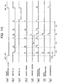
- FIG. 10 (h) it is also possible, as illustrated in FIG. 10 (h) , to provide the clocking means with a timer function such that an ON signal is outputted at predetermined time intervals ⁇ t and based on the ON signal, a turn-on signal is outputted to the switch 9.
- the lithium battery serves as a second power feeding means.
Landscapes
- Engineering & Computer Science (AREA)
- Mechanical Engineering (AREA)
- Physics & Mathematics (AREA)
- General Physics & Mathematics (AREA)
- Radar, Positioning & Navigation (AREA)
- Remote Sensing (AREA)
- Burglar Alarm Systems (AREA)
- Component Parts Of Construction Machinery (AREA)
- Lock And Its Accessories (AREA)
- Output Control And Ontrol Of Special Type Engine (AREA)
Claims (8)
- Diebstahlsicherungssystem, das ausgestattet ist mit:einem Steuersystem (1), das auf einem beweglichen Objekt mit Eigenantrieb mit einer darauf befestigten Maschine (7) als eine Antriebsquelle angeordnet ist und Positionsdetektionsmittel (3) zum Detektieren einer Position des beweglichen Objekts, Sende- bzw. Empfangsmittel (4) zum Ausführen eines Sendens bzw. eines Empfangens nach bzw. von außen und Verarbeitungsmittel (2, 2a) zum Ausführen von vorgegebenen Verarbeitungsvorgängen, die Ausgaben von Laufbefehlen an die Positionsdetektionsmittel (3) und die Sende- bzw. Empfangsmittel (4) enthalten, besitzt, undeinem Steuer-Server (10), der an einem Ort angeordnet ist, der von dem beweglichen Objekt verschieden ist, zum Steuern von Informationen über das bewegliche Objekt, wobei die Informationen Positionsinformationen umfassen, die durch die Positionsdetektionsmittel (3) detektiert werden und über die Sende- bzw. Empfangsmittel (4) gesendet werden,Taktgebemitteln (2c), wobei die Verarbeitungsmittel (2, 2a) Signale von den Taktgebemitteln (2c) empfangen, understen Leistungszuführmitteln (9), um Leistung zumindest zu den Positionsdetektionsmitteln (3) zuzuführen oder nicht zuzuführen,dadurch gekennzeichnet, dass das Diebstahlsicherungssystem ferner umfasst:zweite Leistungszuführmittel (8), um Leistung zumindest an die Taktgebemittel (2c) zuzuführen oder nicht zuzuführen; wobeidie Verarbeitungsmittel erlauben, dass die ersten Leistungszuführmittel (9) kontinuierlich Leistung zuführen, bis eine vorgegebene Zeit von einem Zeitpunkt, zu dem ein Stoppsignal für die Maschine (7) eingeben wird, abläuft, und nach einem Ablaufen der ersten vorgegebenen Zeit wiederholt ein Anweisungssignal ausgeben, das das Zuführen einer Leistung zu vorgegebenen Zeitintervallen durch die ersten Leistungszuführmittel (9) erlaubt.
- Diebstahlsicherungssystem nach Anspruch 1, wobei die Verarbeitungsmittel die Positionsinformationen über das bewegliche Objekt lesen, wie sie durch die Positionsdetektionsmittel (3) detektiert werden, jedes Mal, wenn das Anweisungssignal, das das Zuführen von Leistung erlaubt, in den vorgegebenen Zeitintervallen an die ersten Leistungszuführmittel (9) ausgegeben wird, und nach Vollenden des Lesens der Positionsinformationen die ersten Leistungszuführmittel (9) anweisen, das Zuführen von Leistung zu stoppen.
- Diebstahlsicherungssystem nach Anspruch 2, wobei dann, wenn das Befehlssignal, das das Zuführen von Leistung erlaubt, für eine vorgegebene Anzahl bei den vorgegebenen Zeitintervallen an die ersten Leistungszuführmittel (9) ausgegeben wurde, die Verarbeitungsmittel die Sende- bzw. Empfangsmittel anweisen, die Positionsinformationen über das bewegliche Objekt, die zuletzt durch die Positionsdetektionsmittel (3) detektiert wurden, und ein Signal, das kommuniziert, dass ein Senden bzw. ein Empfangen nach bzw. von außen über die Sende- bzw. Empfangsmittel (4) deaktiviert ist, an den Steuer-Server (10) zu senden.
- Diebstahlsicherungssystem nach Anspruch 2, wobei dann, wenn eine zweite vorgegebene Zeit anschließend an ein Ablaufen der ersten vorgegebenen Zeit abgelaufen ist, die Verarbeitungsmittel die Sende- bzw. Empfangsmittel (4) anweisen, die Positionsinformationen über das bewegliche Objekt, die zuletzt durch die Positionsdetektionsmittel (3) detektiert wurden, und ein Signal, das kommuniziert, dass ein Senden bzw. ein Empfangen nach bzw. von außen über die Sende- bzw. Empfangsmittel (4) deaktiviert wurde, an den Steuer-Server (10) zu senden.
- Diebstahlsicherungssystem nach Anspruch 1, wobei das Steuersystem (1) mit Speichermitteln (2b) zum Speichern der Positionsinformationen über das bewegliche Objekt, wie sie durch die Positionsdetektionsmittel (3) detektiert werden, ausgestattet ist; und die Verarbeitungsmittel Positionsinformationen, die anschließend an die Eingabe des Stoppsignals für die Maschine (7) detektiert werden, mit den in den Speichermitteln (2b) gespeicherten Positionsinformationen vergleichen und dann, wenn ein Abstandsunterschied mindestens eines vorgegebenen Werts bestätigt ist, bestimmen, dass das bewegliche Objekt gestohlen wurde, und die Sende- bzw. Empfangsmittel (4) anweisen, ein Diebstahlsignal zusammen mit den Positionsinformationen an den Steuer-Server (10) zu senden.
- Diebstahlsicherungssystem nach Anspruch 3 oder 4, wobei dann, wenn bestimmt wird, dass das bewegliche Objekt gestohlen wurde, die Verarbeitungsmittel ein Anweisungssignal, das ein kontinuierliches Zuführen von Leistung erlaubt, an die ersten Leistungszuführmittel (9) ausgeben.
- Diebstahlsicherungssystem nach Anspruch 5, wobei die zweiten Leistungszuführmittel (8) verbunden sind, um ein Zuführen einer Leistung an die Sende- bzw. Empfangsmittel (4) auszuführen; und dann, wenn das Anweisungssignal von dem Steuer-Server (10) über die Sende- bzw. Empfangsmittel (4) eingegeben wurde, bevor ein Senden bzw. ein Empfangen nach bzw. von außen über die Sende- bzw. Empfangsmittel (4) deaktiviert wurde, die Verarbeitungsmittel die Sende- bzw. Empfangsmittel (4) anweisen, zumindest die Positionsinformationen, die in den Speichermitteln (2b) gespeichert wurden, an eine Seite des Steuer-Servers (10) zu senden.
- Diebstahlsicherungssystem nach Anspruch 7, wobei dann, wenn ein Signal, das kommuniziert, dass ein Senden bzw. ein Empfangen deaktiviert wurde, über die Sende- bzw. Empfangsmittel (4) an den Steuer-Server (10) gesendet wurde, die Verarbeitungsmittel die zweiten Leistungszuführmittel (8) anweisen, das Zuführen von Leistung zu stoppen.
Applications Claiming Priority (3)
| Application Number | Priority Date | Filing Date | Title |
|---|---|---|---|
| JP2002363947A JP3839400B2 (ja) | 2002-12-16 | 2002-12-16 | 盗難防止装置 |
| JP2002363947 | 2002-12-16 | ||
| PCT/JP2003/016096 WO2004054854A1 (ja) | 2002-12-16 | 2003-12-16 | 盗難防止装置 |
Publications (3)
| Publication Number | Publication Date |
|---|---|
| EP1577180A1 EP1577180A1 (de) | 2005-09-21 |
| EP1577180A4 EP1577180A4 (de) | 2006-04-05 |
| EP1577180B1 true EP1577180B1 (de) | 2016-08-10 |
Family
ID=32588221
Family Applications (1)
| Application Number | Title | Priority Date | Filing Date |
|---|---|---|---|
| EP03780781.5A Expired - Lifetime EP1577180B1 (de) | 2002-12-16 | 2003-12-16 | Diebstahlsicherung |
Country Status (6)
| Country | Link |
|---|---|
| US (1) | US7489049B2 (de) |
| EP (1) | EP1577180B1 (de) |
| JP (1) | JP3839400B2 (de) |
| KR (1) | KR100689938B1 (de) |
| CN (1) | CN1330518C (de) |
| WO (1) | WO2004054854A1 (de) |
Families Citing this family (14)
| Publication number | Priority date | Publication date | Assignee | Title |
|---|---|---|---|---|
| MX2007000555A (es) | 2004-07-15 | 2007-03-07 | Amgen Inc | 1,2,3,4-tetrahidropirazin-2-il acetamidas y su uso como antagonistas de bradicinina para el tratamiento de trastornos relacionados con inflamacion. |
| JP4788756B2 (ja) * | 2004-08-24 | 2011-10-05 | 株式会社デンソー | 車両用受信装置 |
| JP4213151B2 (ja) * | 2005-09-07 | 2009-01-21 | 俊彦 水上 | Gps機能付き携帯通信端末 |
| JP4783643B2 (ja) * | 2006-02-06 | 2011-09-28 | 株式会社小松製作所 | 移動体監視装置および移動体監視システム |
| JP2007276573A (ja) * | 2006-04-04 | 2007-10-25 | Denso Corp | 車両盗難検知装置 |
| EP2026288A3 (de) * | 2007-08-03 | 2010-11-24 | Denso Corporation | Elektronisches Steuersystem und -verfahren zur Fahrzeugdiagnose |
| US20120226410A1 (en) * | 2011-03-04 | 2012-09-06 | Continental Automotive Systems, Inc. | System and method for minimizing the power drain on a battery of a vehicle |
| CN103085758B (zh) * | 2011-10-28 | 2016-10-12 | 上海博泰悦臻网络技术服务有限公司 | 车载终端及车辆监控系统 |
| CN103577208B (zh) * | 2012-08-03 | 2016-09-07 | 纬创资通股份有限公司 | 执行服务器开关机的方法及执行服务器开关机的系统 |
| JP6766689B2 (ja) * | 2017-02-28 | 2020-10-14 | ブラザー工業株式会社 | 移設検知装置、移設検知システム及び移設検知方法 |
| FR3064572B1 (fr) * | 2017-04-04 | 2019-03-22 | Continental Automotive France | Procede d’inhibition temporaire d’une activation a distance d’une fonction presente dans un vehicule automobile |
| CN107088304A (zh) * | 2017-05-24 | 2017-08-25 | 深圳市橙子兄弟信息科技有限公司 | 防盗摇摇车 |
| WO2020170431A1 (ja) * | 2019-02-22 | 2020-08-27 | 本田技研工業株式会社 | 盗難防止装置および発電機盗難防止システム |
| JP7646404B2 (ja) | 2021-03-19 | 2025-03-17 | 本田技研工業株式会社 | 作業機 |
Family Cites Families (48)
| Publication number | Priority date | Publication date | Assignee | Title |
|---|---|---|---|---|
| US5223844B1 (en) * | 1992-04-17 | 2000-01-25 | Auto Trac Inc | Vehicle tracking and security system |
| JPH10133676A (ja) | 1996-10-30 | 1998-05-22 | Pioneer Electron Corp | 情報読み出し制御方法 |
| JPH10336760A (ja) * | 1997-06-04 | 1998-12-18 | Omron Corp | 受信機及びリモートコントロール装置 |
| US6522265B1 (en) * | 1997-06-25 | 2003-02-18 | Navox Corporation | Vehicle tracking and security system incorporating simultaneous voice and data communication |
| DE19733579A1 (de) | 1997-08-02 | 1999-02-04 | Kdm Sicherheitstechnik Gmbh | Verfahren und Einrichtung zum Überwachen von Personen und/oder beweglichen Objekten |
| JP2000072727A (ja) | 1998-08-25 | 2000-03-07 | Mitsui Chemicals Inc | 光学活性α−置換−β−アミノケトン誘導体の製造方法 |
| JP2000073411A (ja) | 1998-08-31 | 2000-03-07 | Yutani Heavy Ind Ltd | 建設機械の盗難防止装置及び盗難防止システム |
| JP2997465B1 (ja) * | 1999-03-11 | 2000-01-11 | 山一電機株式会社 | 配線基板における導電バンプの形成方法 |
| AU770499B2 (en) * | 1999-03-17 | 2004-02-26 | Komatsu Limited | Device for presenting information to mobile |
| JP2000295669A (ja) * | 1999-04-07 | 2000-10-20 | Matsushita Electric Ind Co Ltd | 車載端末装置と情報転送システムと緊急通報システム |
| US6611755B1 (en) * | 1999-12-19 | 2003-08-26 | Trimble Navigation Ltd. | Vehicle tracking, communication and fleet management system |
| JP3723837B2 (ja) * | 2000-01-14 | 2005-12-07 | 富士通テン株式会社 | 盗難通報装置、及び盗難通報システム |
| US6974642B2 (en) | 2000-03-15 | 2005-12-13 | Fujitsu Limited | Carbonaceous protective layer, magnetic recording medium, production method thereof, and magnetic disk apparatus |
| US6522267B2 (en) * | 2000-05-17 | 2003-02-18 | Omega Patents, L.L.C. | Vehicle tracker conserving codes and related methods |
| US6606561B2 (en) * | 2000-05-17 | 2003-08-12 | Omega Patents, L.L.C. | Vehicle tracker including input/output features and related methods |
| US6816089B2 (en) * | 2000-05-17 | 2004-11-09 | Omega Patents, L.L.C. | Vehicle tracker having find alert features and related methods |
| US6798356B2 (en) * | 2000-05-17 | 2004-09-28 | Omega Patents, L.L.C. | Vehicle tracking unit providing direction deviation tracking and related methods |
| US6744384B2 (en) * | 2000-05-17 | 2004-06-01 | Omega Patents, L.L.C. | Vehicle tracker having switchable polarity output terminals and related methods |
| US7031835B2 (en) * | 2000-05-17 | 2006-04-18 | Omega Patents, L.L.C. | Vehicle tracker cooperating with a starter interrupt and related methods |
| US6804605B2 (en) * | 2000-05-17 | 2004-10-12 | Omega Patents, L.L.C. | Vehicle tracker with user registration reminder and related methods |
| US6703946B2 (en) * | 2000-05-17 | 2004-03-09 | Omega Patents, L.L.C. | Vehicle tracking unit having a self diagnostic mode and related methods |
| US6737989B2 (en) * | 2000-05-17 | 2004-05-18 | Omega Patents, L.L.C. | Vehicle tracker including variable frequency transmission and related methods |
| US6819269B2 (en) * | 2000-05-17 | 2004-11-16 | Omega Patents, L.L.C. | Vehicle tracker including battery monitoring feature and related methods |
| US6771188B2 (en) * | 2000-05-17 | 2004-08-03 | Omega Patents, L.L.C. | Vehicle control system for controlling a vehicle function including a vehicle tracking unit and related methods |
| US6741187B2 (en) * | 2000-05-17 | 2004-05-25 | Omega Patents, L.L.C. | Vehicle tracker providing vehicle alarm alert features and related methods |
| US6512466B2 (en) * | 2000-05-17 | 2003-01-28 | Omega Patents, L.L.C. | Vehicle tracker with power saving features and related methods |
| US6509868B2 (en) * | 2000-05-17 | 2003-01-21 | Omega Patents, L.L.C. | Vehicle tracker with user notifications and associated methods |
| US6507786B2 (en) * | 2000-05-17 | 2003-01-14 | Omega Patents, L.L.C. | Vehicle tracker with user registration reminder and related methods |
| US6512465B2 (en) * | 2000-05-17 | 2003-01-28 | Omega Patents, L.L.C. | Vehicle tracker including stationary time determination and associated methods |
| US6798355B2 (en) * | 2000-05-17 | 2004-09-28 | Omega Patents, L.L.C. | Vehicle tracker including security device monitoring bypass feature and related methods |
| US6803861B2 (en) * | 2000-05-17 | 2004-10-12 | Omega Patents, L.L.C. | Vehicle tracking unit with fault condition diagnosis and related methods |
| US6809659B2 (en) * | 2000-05-17 | 2004-10-26 | Omega Patents, L.L.C. | Vehicle tracker with test features and related methods |
| US6693563B2 (en) * | 2000-05-17 | 2004-02-17 | Omega Patents, L.L.C. | Vehicle tracking unit providing theft alert notifications and related methods |
| US6924750B2 (en) * | 2000-05-17 | 2005-08-02 | Omega Patents, L.L.C. | Vehicle tracking unit for controlling operable vehicle devices using a vehicle data bus and related methods |
| US6765500B2 (en) * | 2000-05-17 | 2004-07-20 | Omega Patents, L.L.C. | Vehicle tracker including missed call feature and related methods |
| US6784809B2 (en) * | 2000-05-17 | 2004-08-31 | Omega Patents, L.L.C. | Vehicle tracker including override feature and related methods |
| US6844827B2 (en) * | 2000-05-17 | 2005-01-18 | Omega Patents, L.L.C. | Vehicle tracker including a connector for an upgrade device and related methods |
| US6765499B2 (en) * | 2000-05-17 | 2004-07-20 | Omega Patents, L.L.C. | Vehicle tracker unit providing variable frequency transmission and related methods |
| JP2002127873A (ja) * | 2000-10-27 | 2002-05-09 | Auto Network Gijutsu Kenkyusho:Kk | 自動車盗難防止用照合システム |
| US6738914B2 (en) * | 2001-01-05 | 2004-05-18 | Motorola, Inc. | Method and apparatus for determining whether to wake up a system by detecting a status of a push button switch that is remotely located from the system |
| JP4901027B2 (ja) * | 2001-07-12 | 2012-03-21 | 日立建機株式会社 | 建設機械の位置確認方法および位置表示システム並びに建設機械 |
| CA2355426A1 (en) * | 2001-08-17 | 2003-02-17 | Luther Haave | A system and method for asset tracking |
| JP3603825B2 (ja) * | 2001-08-27 | 2004-12-22 | オムロン株式会社 | 監視システム、中央監視装置、および車載監視装置 |
| JP3635352B2 (ja) * | 2002-06-24 | 2005-04-06 | オムロン株式会社 | 移動体の盗難検出装置及び盗難検出方法 |
| US7110728B2 (en) * | 2003-01-23 | 2006-09-19 | Komatsu Ltd. | Mobile body communication device |
| EP1441077B1 (de) * | 2003-01-24 | 2011-03-16 | Komatsu Ltd. | Mobilkörperkommunikationsgerät |
| US7183666B2 (en) * | 2003-01-24 | 2007-02-27 | Komatsu Ltd. | Movable body start-up locking device |
| KR20060016457A (ko) * | 2004-08-17 | 2006-02-22 | 현대모비스 주식회사 | 차량 도난 방지 시스템 및 도난 방지 방법 |
-
2002
- 2002-12-16 JP JP2002363947A patent/JP3839400B2/ja not_active Expired - Lifetime
-
2003
- 2003-12-16 KR KR20057010908A patent/KR100689938B1/ko not_active Expired - Lifetime
- 2003-12-16 EP EP03780781.5A patent/EP1577180B1/de not_active Expired - Lifetime
- 2003-12-16 US US10/538,883 patent/US7489049B2/en not_active Expired - Lifetime
- 2003-12-16 CN CNB2003801061106A patent/CN1330518C/zh not_active Expired - Lifetime
- 2003-12-16 WO PCT/JP2003/016096 patent/WO2004054854A1/ja not_active Ceased
Also Published As
| Publication number | Publication date |
|---|---|
| WO2004054854A1 (ja) | 2004-07-01 |
| EP1577180A1 (de) | 2005-09-21 |
| JP3839400B2 (ja) | 2006-11-01 |
| US7489049B2 (en) | 2009-02-10 |
| US20060109090A1 (en) | 2006-05-25 |
| KR100689938B1 (ko) | 2007-03-12 |
| EP1577180A4 (de) | 2006-04-05 |
| JP2004199167A (ja) | 2004-07-15 |
| CN1726143A (zh) | 2006-01-25 |
| CN1330518C (zh) | 2007-08-08 |
| KR20050084301A (ko) | 2005-08-26 |
Similar Documents
| Publication | Publication Date | Title |
|---|---|---|
| EP1577180B1 (de) | Diebstahlsicherung | |
| US8626107B2 (en) | System and method for managing communication of a moveable entity for energy conservation | |
| US6696982B2 (en) | Vehicle terminal apparatus and an information transmitting system | |
| KR101531056B1 (ko) | 건설 기계의 위치를 모니터링하기 위한 통신 방법 | |
| US6448927B1 (en) | Position information system | |
| US6844827B2 (en) | Vehicle tracker including a connector for an upgrade device and related methods | |
| JP4735728B2 (ja) | 車載無線通信装置 | |
| US7574192B2 (en) | Method for operating a communication system and objects for such a system | |
| US5764185A (en) | Method and apparatus for controlling antenna and tracking antenna system using the same | |
| KR20060016457A (ko) | 차량 도난 방지 시스템 및 도난 방지 방법 | |
| US7680572B2 (en) | Onboard-equipment control apparatus and onboard-equipment control system | |
| JP2002290596A (ja) | 機械のモーションレコーダおよび機械の監視システム | |
| WO2011088005A1 (en) | An anti-theft system and method for a machine having a communication device and work implement | |
| EP2490038B1 (de) | System und verfahren zur verfolgung des standorts einer bauausrüstung | |
| JP2002173003A (ja) | 土木・建設機械の盗難防止管理システム | |
| IES79451B2 (en) | Alarm apparatus for determining if a vehicle is moved | |
| GB2580605A (en) | A theft deterrent system and method | |
| KR100998458B1 (ko) | 이동체 감시 장치 | |
| JP2009235815A (ja) | 作業機械の位置管理システム、及び作業エリアデータの更新方法 | |
| KR20030035455A (ko) | 산업용 차량의 도난방지 시스템 | |
| JPH08297159A (ja) | Gps受信機及びその制御方法 | |
| KR100786698B1 (ko) | 건설기계의 도난방지시스템 및 그 방법 | |
| EP4395370B1 (de) | Internet-der-dinge-vorrichtungen und verfahren zur steuerung der leistung dafür | |
| KR20120025728A (ko) | 내비게이션을 이용한 차량 도난 방지장치 및 방법 | |
| KR0130640B1 (ko) | 자동차량 추적시스템 |
Legal Events
| Date | Code | Title | Description |
|---|---|---|---|
| PUAI | Public reference made under article 153(3) epc to a published international application that has entered the european phase |
Free format text: ORIGINAL CODE: 0009012 |
|
| 17P | Request for examination filed |
Effective date: 20050617 |
|
| AK | Designated contracting states |
Kind code of ref document: A1 Designated state(s): AT BE BG CH CY CZ DE DK EE ES FI FR GB GR HU IE IT LI LU MC NL PT RO SE SI SK TR |
|
| A4 | Supplementary search report drawn up and despatched |
Effective date: 20060217 |
|
| RBV | Designated contracting states (corrected) |
Designated state(s): DE FR GB IT NL SE |
|
| RIC1 | Information provided on ipc code assigned before grant |
Ipc: B60R 25/10 20060101AFI20040702BHEP Ipc: G08G 1/123 20060101ALI20060213BHEP Ipc: B60R 25/04 20060101ALI20060213BHEP Ipc: G08B 13/00 20060101ALI20060213BHEP |
|
| RIN1 | Information on inventor provided before grant (corrected) |
Inventor name: SUGIYAMA, GENROKUC/O HITACHI CONST.MACHIN. CO LTD Inventor name: SHIBAMORI, KAZUHIROC/O HITACHI CONST. MACHIN.CO Inventor name: KOMATSU, HIDEKIC/O HITACHI CONST. MACHIN. CO.LTD Inventor name: ADACHI, HIROYUKIC/O HITACHI CONST. MACHIN. CO.LTD Inventor name: SHIBATA, KOICHIC/O HITACHI CONST. MACHIN. CO. LTD |
|
| 17Q | First examination report despatched |
Effective date: 20100726 |
|
| GRAP | Despatch of communication of intention to grant a patent |
Free format text: ORIGINAL CODE: EPIDOSNIGR1 |
|
| INTG | Intention to grant announced |
Effective date: 20160218 |
|
| GRAS | Grant fee paid |
Free format text: ORIGINAL CODE: EPIDOSNIGR3 |
|
| GRAA | (expected) grant |
Free format text: ORIGINAL CODE: 0009210 |
|
| AK | Designated contracting states |
Kind code of ref document: B1 Designated state(s): DE FR GB IT NL SE |
|
| REG | Reference to a national code |
Ref country code: GB Ref legal event code: FG4D |
|
| REG | Reference to a national code |
Ref country code: NL Ref legal event code: FP |
|
| REG | Reference to a national code |
Ref country code: DE Ref legal event code: R096 Ref document number: 60349243 Country of ref document: DE |
|
| REG | Reference to a national code |
Ref country code: FR Ref legal event code: PLFP Year of fee payment: 14 |
|
| PG25 | Lapsed in a contracting state [announced via postgrant information from national office to epo] |
Ref country code: SE Free format text: LAPSE BECAUSE OF FAILURE TO SUBMIT A TRANSLATION OF THE DESCRIPTION OR TO PAY THE FEE WITHIN THE PRESCRIBED TIME-LIMIT Effective date: 20160810 |
|
| REG | Reference to a national code |
Ref country code: DE Ref legal event code: R097 Ref document number: 60349243 Country of ref document: DE |
|
| PLBE | No opposition filed within time limit |
Free format text: ORIGINAL CODE: 0009261 |
|
| STAA | Information on the status of an ep patent application or granted ep patent |
Free format text: STATUS: NO OPPOSITION FILED WITHIN TIME LIMIT |
|
| 26N | No opposition filed |
Effective date: 20170511 |
|
| REG | Reference to a national code |
Ref country code: FR Ref legal event code: PLFP Year of fee payment: 15 |
|
| PGFP | Annual fee paid to national office [announced via postgrant information from national office to epo] |
Ref country code: NL Payment date: 20221114 Year of fee payment: 20 Ref country code: IT Payment date: 20221111 Year of fee payment: 20 Ref country code: GB Payment date: 20221027 Year of fee payment: 20 Ref country code: FR Payment date: 20221110 Year of fee payment: 20 Ref country code: DE Payment date: 20221102 Year of fee payment: 20 |
|
| REG | Reference to a national code |
Ref country code: DE Ref legal event code: R071 Ref document number: 60349243 Country of ref document: DE |
|
| REG | Reference to a national code |
Ref country code: NL Ref legal event code: MK Effective date: 20231215 |
|
| REG | Reference to a national code |
Ref country code: GB Ref legal event code: PE20 Expiry date: 20231215 |
|
| PG25 | Lapsed in a contracting state [announced via postgrant information from national office to epo] |
Ref country code: GB Free format text: LAPSE BECAUSE OF EXPIRATION OF PROTECTION Effective date: 20231215 |
|
| PG25 | Lapsed in a contracting state [announced via postgrant information from national office to epo] |
Ref country code: GB Free format text: LAPSE BECAUSE OF EXPIRATION OF PROTECTION Effective date: 20231215 |