EP1577235A2 - Procédé et appareil pour mettre des feuilles de verre dans des positions prédéfinies - Google Patents
Procédé et appareil pour mettre des feuilles de verre dans des positions prédéfinies Download PDFInfo
- Publication number
- EP1577235A2 EP1577235A2 EP04011111A EP04011111A EP1577235A2 EP 1577235 A2 EP1577235 A2 EP 1577235A2 EP 04011111 A EP04011111 A EP 04011111A EP 04011111 A EP04011111 A EP 04011111A EP 1577235 A2 EP1577235 A2 EP 1577235A2
- Authority
- EP
- European Patent Office
- Prior art keywords
- glass plate
- suction
- plate
- air
- plate member
- Prior art date
- Legal status (The legal status is an assumption and is not a legal conclusion. Google has not performed a legal analysis and makes no representation as to the accuracy of the status listed.)
- Withdrawn
Links
- 239000011521 glass Substances 0.000 title claims abstract description 243
- 238000000034 method Methods 0.000 title claims abstract description 40
- 238000003825 pressing Methods 0.000 claims abstract description 48
- 238000007667 floating Methods 0.000 claims abstract description 9
- 238000012546 transfer Methods 0.000 claims description 47
- 230000010006 flight Effects 0.000 claims description 28
- 238000005452 bending Methods 0.000 claims description 19
- 244000273618 Sphenoclea zeylanica Species 0.000 claims description 15
- 238000012937 correction Methods 0.000 claims description 14
- 230000033001 locomotion Effects 0.000 claims description 12
- 238000006073 displacement reaction Methods 0.000 claims description 10
- 229920001971 elastomer Polymers 0.000 claims description 9
- 238000007664 blowing Methods 0.000 claims description 8
- 238000001514 detection method Methods 0.000 claims description 7
- 238000007599 discharging Methods 0.000 claims description 3
- 238000000926 separation method Methods 0.000 description 9
- 230000000903 blocking effect Effects 0.000 description 3
- 239000005357 flat glass Substances 0.000 description 3
- 238000003780 insertion Methods 0.000 description 2
- 230000037431 insertion Effects 0.000 description 2
- 238000004519 manufacturing process Methods 0.000 description 2
- 230000002093 peripheral effect Effects 0.000 description 2
- 229920002449 FKM Polymers 0.000 description 1
- 229920000459 Nitrile rubber Polymers 0.000 description 1
- 229910000831 Steel Inorganic materials 0.000 description 1
- 229920006311 Urethane elastomer Polymers 0.000 description 1
- 230000002159 abnormal effect Effects 0.000 description 1
- 230000005856 abnormality Effects 0.000 description 1
- 230000006835 compression Effects 0.000 description 1
- 238000007906 compression Methods 0.000 description 1
- 238000005520 cutting process Methods 0.000 description 1
- 238000003384 imaging method Methods 0.000 description 1
- 239000000463 material Substances 0.000 description 1
- 238000012545 processing Methods 0.000 description 1
- 229920005989 resin Polymers 0.000 description 1
- 239000011347 resin Substances 0.000 description 1
- 238000004826 seaming Methods 0.000 description 1
- 229920002379 silicone rubber Polymers 0.000 description 1
- 239000004945 silicone rubber Substances 0.000 description 1
- 239000010959 steel Substances 0.000 description 1
- 229920003002 synthetic resin Polymers 0.000 description 1
- 239000000057 synthetic resin Substances 0.000 description 1
- 239000005341 toughened glass Substances 0.000 description 1
- 239000011800 void material Substances 0.000 description 1
Images






Classifications
-
- B—PERFORMING OPERATIONS; TRANSPORTING
- B65—CONVEYING; PACKING; STORING; HANDLING THIN OR FILAMENTARY MATERIAL
- B65G—TRANSPORT OR STORAGE DEVICES, e.g. CONVEYORS FOR LOADING OR TIPPING, SHOP CONVEYOR SYSTEMS OR PNEUMATIC TUBE CONVEYORS
- B65G49/00—Conveying systems characterised by their application for specified purposes not otherwise provided for
- B65G49/05—Conveying systems characterised by their application for specified purposes not otherwise provided for for fragile or damageable materials or articles
- B65G49/06—Conveying systems characterised by their application for specified purposes not otherwise provided for for fragile or damageable materials or articles for fragile sheets, e.g. glass
- B65G49/068—Stacking or destacking devices; Means for preventing damage to stacked sheets, e.g. spaces
-
- B—PERFORMING OPERATIONS; TRANSPORTING
- B65—CONVEYING; PACKING; STORING; HANDLING THIN OR FILAMENTARY MATERIAL
- B65G—TRANSPORT OR STORAGE DEVICES, e.g. CONVEYORS FOR LOADING OR TIPPING, SHOP CONVEYOR SYSTEMS OR PNEUMATIC TUBE CONVEYORS
- B65G49/00—Conveying systems characterised by their application for specified purposes not otherwise provided for
- B65G49/05—Conveying systems characterised by their application for specified purposes not otherwise provided for for fragile or damageable materials or articles
- B65G49/06—Conveying systems characterised by their application for specified purposes not otherwise provided for for fragile or damageable materials or articles for fragile sheets, e.g. glass
- B65G49/061—Lifting, gripping, or carrying means, for one or more sheets forming independent means of transport, e.g. suction cups, transport frames
-
- B—PERFORMING OPERATIONS; TRANSPORTING
- B65—CONVEYING; PACKING; STORING; HANDLING THIN OR FILAMENTARY MATERIAL
- B65G—TRANSPORT OR STORAGE DEVICES, e.g. CONVEYORS FOR LOADING OR TIPPING, SHOP CONVEYOR SYSTEMS OR PNEUMATIC TUBE CONVEYORS
- B65G49/00—Conveying systems characterised by their application for specified purposes not otherwise provided for
- B65G49/05—Conveying systems characterised by their application for specified purposes not otherwise provided for for fragile or damageable materials or articles
- B65G49/06—Conveying systems characterised by their application for specified purposes not otherwise provided for for fragile or damageable materials or articles for fragile sheets, e.g. glass
- B65G49/067—Sheet handling, means, e.g. manipulators, devices for turning or tilting sheet glass
-
- B—PERFORMING OPERATIONS; TRANSPORTING
- B65—CONVEYING; PACKING; STORING; HANDLING THIN OR FILAMENTARY MATERIAL
- B65G—TRANSPORT OR STORAGE DEVICES, e.g. CONVEYORS FOR LOADING OR TIPPING, SHOP CONVEYOR SYSTEMS OR PNEUMATIC TUBE CONVEYORS
- B65G2249/00—Aspects relating to conveying systems for the manufacture of fragile sheets
- B65G2249/04—Arrangements of vacuum systems or suction cups
-
- B—PERFORMING OPERATIONS; TRANSPORTING
- B65—CONVEYING; PACKING; STORING; HANDLING THIN OR FILAMENTARY MATERIAL
- B65G—TRANSPORT OR STORAGE DEVICES, e.g. CONVEYORS FOR LOADING OR TIPPING, SHOP CONVEYOR SYSTEMS OR PNEUMATIC TUBE CONVEYORS
- B65G2249/00—Aspects relating to conveying systems for the manufacture of fragile sheets
- B65G2249/04—Arrangements of vacuum systems or suction cups
- B65G2249/045—Details of suction cups suction cups
Definitions
- the present invention relates to a system for putting plate members (e.g., glass plates) to target positions, particularly to a system for automatically supplying glass plates (standing in a pallet) one by one with high speed into a bending furnace (equipped with hearth beds) in the production of curved glass plates for vehicular and industrial uses.
- plate members e.g., glass plates
- Japanese Patent Publication JP-A-7-61597 discloses an apparatus for transferring glass plates (standing in a pallet) one by one. This apparatus is equipped with a mechanism for removing each interleaf paper between two glass plates.
- Japanese Patent Publication JP-A-11-35150 discloses an apparatus for taking glass plates one by one to safely introduce glass plates into a glass cutting machine, etc.
- Japanese Patent Publication JP-A-2000-296435 discloses a method for positioning glass plates with shapes other than rectangle.
- Japanese Patent Publication JP-A-6-247594 discloses an apparatus for positioning glass plates with shapes other than rectangle.
- Japanese Utility Model Publication JP-U-5-82941 discloses an apparatus for transferring glass plates one by one.
- This apparatus has a frame, suction cups formed on the frame, and a reference sensor and two additional sensors. These three sensors are disposed at three apexes of a triangle and serve to adjust the angle of the frame relative to a glass plate that is positioned at the forefront of the glass plates.
- Japanese Patent Publication JP-A-2-43143 discloses a robotic suction hand for transferring plate members one by one by applying suction.
- Japanese Patent Publication JP-A-7-315570 discloses an apparatus for separating a first glass plate at the top of a pile of glass plates from a second glass plate next to the first glass plate by ejecting compressed air.
- a system for automatically supplying glass plates into a bending furnace comprises:
- a method for putting a glass plate to a target position comprises the steps of:
- an apparatus for putting a glass plate to a target position comprises:
- a first robot for transferring standing plate members one by one comprising:
- a first method for transferring standing plate members one by one using the first robot comprises the steps of:
- a second method for transferring standing plate members one by one using a second robot comprises:
- the second method comprises the steps of:
- a method for transferring standing plate members one by one comprises the steps of:
- an apparatus for separating standing plate members one by one comprises:
- the apparatus can be used for conducting the steps (a) to (d) of the method.
- a system for automatically supplying glass plates into a bending furnace is described in detail in the following.
- the system has a first transfer means 10 (e.g., a transfer robot 11) for transferring a first glass plate 1 positioned at the forefront of glass plates 1 standing in a pallet 4 onto a positioning table 32 by supporting the first glass plate 1 with suction cups 13 of a transfer hand 12.
- the system further has a detecting means 30 for detecting the real coordinate of the first glass plate 1 on the positioning table 32 by imaging the first glass plate 1 on the positioning table 32 with a camera 31 that is placed above the positioning table 32.
- the system further has a second transfer means 50 for transferring the first glass plate 1 from the positioning table 32 to a target position on a conveyance table (air table) 2, while the position of the first glass plate 1 is corrected based on a difference between the real coordinate and a reference coordinate of the first glass plate 1 on the positioning table 32. Therefore, even if the real coordinate of the first glass plate 1 on the positioning table 32 deviates from its reference coordinate, it is possible to position the first glass plate 1 at a target position on the conveyance table 2 by such correction.
- the system further has a separation means 20 in order to prevent the above-explained phenomena "blocking" by blowing air from an air nozzle 21 of the separation means 20 to provide a space between the first glass plate 1 at the forefront and the second glass plate next thereto. Details of the separation means 20 are explained hereinafter in accordance with the fourth aspect of the present invention. By using the separation means, it is possible to speedily and surely take only the first glass plates 1 one by one from the pallet 4.
- the position determination camera (e.g., CCD camera) 31 that is placed above the positioning table 32 takes an image of the real coordinate of the first glass plate 1 on the positioning table 32, and then deviation of the real coordinate (corresponding to the real position) of the first glass plate 1 from its reference coordinate (corresponding to its proper position) on the positioning table 32 is determined by an image processing device or the like (not shown in the drawings).
- an image processing device or the like not shown in the drawings.
- the first glass plate 1 it is optional to use a plurality of position determination cameras 31 to take images of the first glass plate 1 on the positioning table 32 and then to combine the resulting image data together to determine deviation of the real coordinate of the first glass plate 1 from its reference coordinate on the positioning table 32.
- the second transfer means 50 transfers the first glass plate 1 from the positioning table 32 onto the conveyance table 2 by supporting the first glass plate 1 with suction cups 53 formed on a robotic hand 52 of a transfer robot 51.
- the suction cups 53 of the robotic hand 52 are brought into abutment with the first glass plate 1 placed on the positioning table 32 in a manner that the robotic hand 52 takes a corrected position and a corrected angle on the positioning table 32, in accordance with deviation of the first glass plate 1, which is actually placed on the positioning table, from its reference position and its reference angle.
- the relative position of the robotic hand 52 on the first glass plate placed on the positioning table 32 is always the same.
- the movement of the robotic hand 52 from the positioning table 32 to the conveyance table 2 is finely adjusted each time such that the first glass plate 1 always takes a proper position on the conveyance table 2.
- the deviation of the first glass plate on the positioning table 32 is corrected each time by the adjusted movement of the robotic hand 52 from the positioning table 32 to the conveyance table 2. With this correction, it is possible to properly bring the first glass plate 1 into contact with predetermined flights (positioning guides) 62 to lead the first glass plate 1 into a bending furnace.
- the flights 62 are fixed at predetermined intervals to a conveyance chain 3 that is disposed in the vicinity of a side edge of the conveyance table 2.
- the first glass plate 1 is floated above the conveyance table 2 by air discharged upward from small openings formed on the top surface of the conveyance table 2. Furthermore, the first glass plate 1 is brought into abutment at its predetermined ends with the flights 62. Under this condition, the glass plates are guided one by one into the furnace by the flights.
- One distinction tag which is not brought into abutment with the first glass plate 1, is combined with two or three flights 62 for one glass sheet to be conveyed.
- the distinction tag and the flights 62 are each attached to ends of extension pins that are fixed to the conveyance chain 3 in a manner to extend shafts of outer links of the conveyance chain 3.
- the distances of the corresponding flights 62 from the distinction tag are changed.
- the corresponding flights 62 are attached to the extension pins to have suitable distances from the distinction tag.
- the distinction tag is detected by the detection camera 61.
- the flights 62 are detected by the detection camera.
- the first glass plate 1 is brought at a suitable timing with those flights 62 by the transfer robot 51.
- window glass plates for example, automotive right and left side windows that are dissymmetrical with each other, it may become necessary in some cases to put the glass plates one by one upside down on the positioning table 32.
- the first glass plate 1 is transferred from the pallet 4 onto a reversing hand (e.g., a robotic hand) 41 of a reversing member 40 (e.g., a robot), not onto the positioning table 32, such that the front and back surfaces of the first glass plate 1 in the pallet 4 respectively turn into the top and bottom surfaces of the first glass plate 1 on the reversing hand 41.
- the first glass plate 1 is fixed onto suction cups 42 of the reversing hand 41 by applying suction to the suction cups 42.
- the first glass plate 1 is placed upside down on the positioning table 32 by moving the reversing member 40.
- the first aspect of the present invention it is possible to concurrently conduct the steps of (a) the first transfer of the glass plate 1 from the pallet 4 onto the positioning table 32 optionally via the reversing member 40, (b) the detection of the real coordinate of the glass plate 1 on the positioning table 32 by the detection means 30, and (c) the second transfer of the glass plate 1 from the positioning table 32 to the target position on the conveyance table 2.
- the step (c) is described in detail hereinafter in accordance with the second aspect of the present invention.
- the first glass plate 1 is transferred from the positioning table 32 onto the conveyance table 2, while the first glass plate 1 is supported by the suction cups 53 of the second transfer means 50. Then, it is necessary to bring the first glass plate 1 into abutment with the predetermined flights.
- the flights are attached to ends of the extension pins fixed to the conveyance chain 3 in a manner to extend the shafts of the outer links of the conveyance chain 3.
- the transfer distance of each glass plate until each glass plate takes a position in abutment with the flights varies slightly due to extension of the conveyance chain or due to that the flights attached to the extension pins do not always take constant positions.
- the glass plate In order to absorb the variation of the above transfer distance, the glass plate is put at a preliminary position above the conveyance table 2 that discharges air upwardly. Then, suction of the suction cups 53 is released, while air is discharged upwardly from the conveyance table 2. Then, the robotic hand 52 is moved toward the flights 62, while a pressing member 54 of the robotic hand 52 is in abutment with the glass plate 1. Under this condition, the glass plate is horizontally movable or slidable relative to the robotic hand. Therefore, the variation of the transfer distance can be absorbed by the horizontal movement of the glass plate. In other words, the position of the glass plate relative to the flights is corrected automatically, surely, precisely and easily with high speed due to play of the flights, when each glass plate abuts against the flights. The transfer of the glass plate to bring it into abutment with the flights is described in detail hereinafter in accordance with the second aspect of the present invention.
- a method and an apparatus for putting a glass plate to a target position are described in detail in accordance with the second aspect of the present invention. It is optional to use this method and this apparatus in the second transfer (according to the first aspect of the present invention) of the first glass plate from the positioning table to the target position on the conveyance table (see Fig. 1).
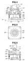
- an apparatus 101 for putting a glass plate G to a target position can perform the sequential steps of (a) horizontally putting the glass plate G at a predetermined position above an air table (conveyance table) 102 that discharges air upwardly, while the glass plate G is supported by a suction cup (suction member) 131 formed on a robotic hand 111 of a robot 110 or the like, (b) releasing suction of the suction cup 131, while air is discharged upwardly from the air table 102, thereby floating the glass plate G at the preliminary position above the air table 102, and (c) moving a pressing member 135 (made of sponge rubber or the like) in a horizontal direction, while the pressing member 135 is in abutment with the top surface of the glass plate G and while air is discharged upwardly from the air table 102, thereby moving the glass plate G in the horizontal direction from the preliminary position above the air table to the target position above the air
- the air table 102 can have on its top surface many small openings for discharging air upwardly. With this, the glass plate G can be floated above the air table 102.
- the robotic hand 111 has (a) a supporting plate 113 fixed at an end of a robotic arm 112 and (b) a drive means 120 that is attached to a middle portion of the supporting plate 113 and moves a suction means 130 up and down by a drive cylinder 121.
- the drive cylinder 121 is attached to the center of the supporting plate 113, and a movable plate 127 is connected to an end of a cylinder rod 122 through a bracket 128.
- This cylinder rod 122 is extendible downward by energizing the drive cylinder 121.
- the suction cup 131 is formed as the suction means 130 at a central portion of the movable plate 127
- the supporting plate 113 is formed at its both ends with a pair of cylindrical guides 123, and guiding shafts 124 are slidably received in the cylindrical guides 123.
- Each guiding shaft is formed at its upper end with a stopper 126 and is connected at its lower end to an end of the movable plate 127 through a fixing member 125.
- the drive cylinder 121 is set to make the cylinder rod 122 extended downwardly.
- the cylinder rod 122 is withdrawn upwardly to separate the robotic hand 111 from the glass plate G. With this, it is possible to prevent the glass plate G from hitting against the positioning guides that move together with the chain.
- the suction cup 131 has a bottom peripheral portion made of rubber, and the pressing member (made of a sponge rubber) 135 is bonded to the bottom peripheral portion to have a large frictional force between the pressing member 135 and the glass plate G.
- the suction cup 131 has a plurality of stoppers 132 in its inside space in order to prevent the suction cup 131 from having an insufficient suction when a suction conduit 133 is closed by an excessive compression of the pressing member 135.
- a second robotic hand according to another embodiment of the second aspect of the present invention is explained in detail in the following.
- the second robotic hand is similar to the above-explained robotic hand, except in that pressing members 135 are disposed to be outwardly away from the suction cup 131. Therefore, parts of the second robotic hand that are similar to those of the first robotic hand are denoted by the same numerals as those of the first robotic hand, and their detailed explanations are omitted.
- cylindrical guides 138 are provided at four corner portions of a movable plate 127.
- Four pressing rods 137 are slidably received in the cylindrical guides 138 and are formed at their upper ends with stoppers 139 and at their lower ends with pressing members 135.
- a spring member 136 is provided in a manner to surround each pressing rod 137 between the pressing member 135 and the cylindrical guide 138. With this, each pressing member 135 is biased downwardly by repulsive force of the spring member 136. Each pressing rod 137 is prevented from falling down by the stopper 139.
- suction is applied to the suction cup 131 under a condition that the spring members 135 are compressed by a certain degree.
- first or second method suction is released at a position that is slightly higher than the preliminary position. With this, the glass plate is lowered to the preliminary position by its own weight, and the glass plate is separated from the suction cup 131, but is still in abutment with the pressing members 135.
- suction is released at the preliminary position. Then, the robotic hand is slightly raised in a manner that the glass plate is separated from the suction cup, but is still in abutment with the pressing members 135.
- the pressing member 135 is made of a sponge rubber or the like to give a high frictional force between the pressing member 135 and the glass plate surface.
- the glass plate is moved horizontally by such frictional force to bring the glass plate into abutment with the positioning guides 103. Even if the pressing member is moved further, the pressing member slides over the glass plate, and the glass plate is kept in abutment with the positioning guides 103, since the frictional force is not so strong.
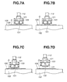
- the glass plate is put at a preliminary position (a middle position) above the air table 102 by moving the robotic hand 112, while the glass plate G is supported by the suction cup 131 through suction of the suction cup 131. Then, suction of the suction cup 131 is released, while air is discharged upwardly from small openings of the air table 102, thereby floating the glass plate G at the preliminary position above the air table 102. It suffices to have an air pressure to slightly float the glass plate G (e.g., 2 or 3 mm) above the air table 102. Under the floating condition, the glass plate G is pressed upwardly against the suction cup 131.
- the robotic hand 112 is moved horizontally toward the positioning guides 103 to bring the glass plate G into abutment with the positioning guides 103 by a frictional force between the glass plate G and the pressing member 135.
- the robotic hand 112 slides over the glass plate G since the frictional force is not so strong, and the glass plate G is kept in abutment with the positioning guides 103 (see Fig. 7C).
- the robotic arm 112 is raised (see Fig. 7D). With this, the positioning of the glass plate G is completed.
- the glass plate is put at a preliminary position (a middle position) above the air table 102 by moving the robotic hand 112, while the glass plate G is supported by the suction cup 131 through suction of the suction cup 131 and while the pressing members 135 are biased against the glass plate G. Then, suction of the suction cup 131 is released, while air is discharged upwardly from small openings of the air table 102, thereby floating the glass plate G at the preliminary position above the air table 102. It suffices to have an air pressure to slightly float the glass plate G (e.g., 2 or 3 mm) above the air table 102. Under the floating condition, the glass plate G is pressed upwardly against the suction cup 131 and the pressing members 135.
- the robotic hand 112 may slightly be raised. With this, the suction cup 131 is separated from the glass plate G, but the pressing members 135 are kept in contact with the glass plate G. Under this condition, the robotic hand 112 is moved horizontally toward the positioning guides 103 to bring the glass plate G into abutment with the positioning guides 103 by a frictional force between the glass plate G and the pressing member 135. When the robotic hand 112 is moved further toward the positioning guides 103, the robotic hand 112 slides over the glass plate G since the frictional force is not so strong, and the glass plate G is kept in abutment with the positioning guides 103 (see Fig. 8C). After the robotic arm 112 is moved horizontally by a predetermined distance toward the positioning guides 103, the robotic arm 112 is raised (see Fig. 8D). With this, the positioning of the glass plate G is completed.
- the glass plate G is transferred to the place of the next step (e.g., a bending furnace).
- the next step e.g., a bending furnace
- the glass plate G is not particularly limited in shape. It may be rectangular, triangular, or trapezoidal.
- the positioning guides 103 may be attached to a conveyance chain that moves at a constant speed or may be attached at rest to the air table.
- the second aspect of the present invention it is possible to bring glass plates one by one assuredly and easily with high precision and with high speed into abutment with positioning guides (flights) that may have play, even if the glass plates have various shapes.
- first and second robots and the first and second methods for transferring standing plate members e.g., glass plates
- the first or second robot and the first or second method may respectively be used as the first transfer means and the first transfer of the above-explained system (see Fig. 1) according to the first aspect of the present invention
- the first robot (articulated robot) 203 which is pivotable and movable toward any direction, has a robotic arm 204 and a robotic hand (suction hand) 210 formed on an end of the robotic arm 204.
- the robotic hand 210 is formed at its front end with a plurality of suction members 211 (e.g., three suction members, as shown in Figs. 9 and 10A) for automatically and continuously transferring a plate member 201 that is positioned at the forefront of the plate members 201 standing in a pallet 202, by moving the robotic arm 204 while suction is applied to the suction members 211 to support the plate member 201.
- the robotic hand 210 is boxlike in shape and has a front plate member 210a.
- This front plate member 210a has three circular openings, through which three hollow guide members 213 are fixed to the front plate member 210a in a manner that the axis of each hollow guide member 213 is perpendicular to the front plate member 210a.
- Each hollow guide member 213 has a front portion, which projects from the front plate member 210a, and a back portion, which is received in the inside of the robotic hand 210 (see Fig. 10B).
- Each suction member 211 has (a) a suction cup 211a (made of rubber), (b) a hollow stem member 212 that extends from the suction cup 211a and is slidably inserted in the guide member 213, and (c) a dog 215 attached to the back end of the stem member 212.
- the stem 212 has a central void space for applying suction to the suction cup 211a.
- a spring 214 is disposed between the suction cup 211a and the front end of the guide member 213 such that the stem member 212 is slidably movable in the guide member 213 when the suction cup 211a is pressed against the plate member 201 by moving the robotic hand 210 toward the plate member 201.
- the dog 215 is a member to be sensed by the after-mentioned first and second sensors. Furthermore, the dog 215 serves as a stopper for preventing the stem member 212 from coming out of the guide member 213.
- a pair of first and second sensors 216 and 217 is provided for each dog 215 and is fixed to a support member extending from the front plate 210a.
- a pair of first and second sensors 216 and 217 is disposed at a suitable position that is away from the front plate member 210a and is in the proximity of the track of the reciprocal movement of the dog 215 such that the dog 215 is sensed by the first and/or second sensor when the dog 215 moves to a position at which the dog 215 is in contact with or in the proximity of the first and/or second sensor. Therefore, it is possible to determine the position of the dog relative to the first and second sensors 216 and 217. In other words, it is possible to determine the degree of projection of the suction cup 211a from the front plate member 210a.
- the first and second sensors 116 and 117 are not particularly limited, as long as they sense the dog 115. They may be proximity sensors, photoelectric sensors, contact-type limit switches, etc.
- Fig. 10A it is preferable to provide at least three of the suction cups 211a in vertical and horizontal directions. With this, it is possible to correct the angle of the front plate member 210a relative to the plate member 201 in vertical and horizontal directions.
- each dog 215 is moved backward and then takes a reference position at which the back end of the dog 215 is in front of the first sensor 216 and is slightly away from the second sensor. Therefore, all the first sensor 216 are switched on at the reference position to send a signal, but all the second sensor 217 are still switched off at the reference position not to send a signal.
- suction cups 211a are arranged parallel to the front major surface of the plate member 201 at the reference position. If suction is applied to the suction cups 211a at the reference position, it is possible to have a predetermine suction at each suction cup 211a to firmly support the plate member 201.
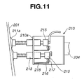
- the robotic hand 210 In order to firmly support the plate member 201 by the robotic hand 210, it is possible to move the robotic hand 210 toward the plate member 201 in a manner to obtain a suitable condition in which front plate member 210a is parallel with the plate member 201. In other words, if the robotic hand 210 (the front plate member 210a) is inclined relative to the plate member (see Fig. 11), it is possible to adjust the angle of the robotic hand 210 relative to the plate member 201 to obtain the suitable condition.
- Whether the robotic hand 210 is inclined or not relative to the plate member 201 can be determined by the data of the first and second sensors 216 and 217. For example, when all the first sensors 216 are switched on and all the second sensors 217 are switched off; the robotic hand 210 can be determined as being not inclined relative to the plate member 201.
- the robotic hand 210 In order to transfer the plate member 1, the robotic hand 210 is moved toward the plate member 201 in a manner to press the suction cups 211a against the plate member 201 until any one of the first sensors is switched on. Then, it is optimum to continue to move the robotic hand 210 to take the above-mentioned reference position at which all the first sensors 216 are switched on and at which all the second sensors 217 are switched off. According to the present invention, however, it is not necessary to take the reference position. When the robotic hand 210 is still inclined relative to the plate member 201, some of the first sensors 216 are switched on, but the remainders of the first sensors 216 are still switched off.
- the robotic hand 210 is still inclined relative to the plate member 201, suction is applied to the suction cups 211a, and the pressure of each suction cup 211a is checked whether or not it has reached a requisite pressure that enables a firm supporting of the plate member 201. If not, the angle of the robotic hand 210 is corrected stepwise by a predetermined angle by a controller (not shown in the drawings), based on on-off data of the first and second sensors 216 and 217, toward the reference position, and the pressure of each suction cup 211a is checked again. These procedures are continued until the pressure of each suction cup 211a reaches the requisite pressure.
- each suction cup 211a Once the pressure of each suction cup 211a reaches the requisite pressure, signals of data (the positional data, the angular data and the like) of the robotic hand 210 are sent to the controller, and then the robotic hand 210 transfers the plate member 201 from the pallet 2 to a target position, irrespective of whether or not the robotic hand 210 is inclined relative to the plate member 201. Even if the robotic hand 210 is inclined relative to the plate member 201, the inclination is very small when the pressure of each suction cup 211a has already reached the requisite pressure.
- the angle of the robotic hand 210 is corrected by the controller in a manner to decrease the inclination of the robotic hand 210 relative to the previous plate member 201, based on the previous data of the first and second sensors 216 and 217, in view of the fact that the angular position of the next plate member 201 in the pallet 2 is substantially the same as that of the previous plate member 201 (see Fig. 13).
- the above-mentioned angle correction of the robotic hand 210 for the next the plate member 201 is conducted continuously and stepwise by a predetermined angle as the transfer of the plate members 201 continues. Therefore, the angle of the robotic hand 210 is adjusted continuously and stepwise toward a condition in which the angle of the robotic hand 210 is in parallel with the plate member 201.
- the predetermined angle is, for example, 1 degree and may vary depending on the thickness and the height of the plate member 201 and the average space between the lower end of the instant plate member and that of the next one.
- the second robot according to the third aspect of the present invention is identical with the above-mentioned first robot except in that the former has a plurality of displacement sensors (not shown in the drawings) in place of a plurality of the first and second sensors of the latter.
- Each displacement sensor is provided for each suction cup 211a and is capable of measuring the change of the distance between the corresponding suction cup 211a and the robotic hand 210.
- the suction cup 211a has a thin lip portion and is made of a material such as nitrile rubber, silicone rubber, viton rubber, and urethane rubber.
- the plate members 201 may be tempered glass plates, half-tempered ones, non-tempered ones, synthetic resin boards, steel plates, and panel members.
- the plate members 201 may be flat or moderately curved.
- the separation apparatus for separating standing plate members one by one and an apparatus (hereinafter “the separation apparatus") for separating standing plate members one by one are described in detail in accordance with the present invention, as follows.
- this apparatus can be used in this method.
- the apparatus and the method may respectively be the separation means and the first transfer of the system (see Fig. 1) according to the first aspect of the present invention.
- the separation apparatus 301 may comprise:
- the plate member detecting means 320, the air blower 330 and the projection means 340 are attached to the traveling head 312.
- the moving means 310 moves on a rail 311 in a horizontal direction at a level higher than that of the top surface of the plate members 302 standing in the pallet 303, toward the forefront plate member and then toward the rearmost plate member.
- the apparatus may further comprise a means 360 for moving the sensor 321 to a position above the top surface of the standing plate members such that the sensor can escape from the movement of a transfer means (e.g., a robotic hand) for transferring the forefront plate member.
- a transfer means e.g., a robotic hand
- the plate member detecting means 320 comprises the sensor 321 formed at a lower end of an arm 322 that is hung on the traveling head 312.
- the sensor 321 sends a signal, when it takes a position that is in contact with or in the proximity of an upper end of the front surface of the forefront plate member 302, thereby detecting its position.
- the sensor may be a contact-type limit switch, photoelectric proximity sensor, or the like.
- the air blower 330 comprises (a) the air nozzle 331 attached to the traveling head 312 and (b) a solenoid valve (not shown in the drawings). Air is ejected from the air nozzle 331 by energizing the air blower 330, and it is possible to stop or restart the air ejection by closing or opening the solenoid valve.
- the air blower 330 ejects air into the boundary between the forefront plate member and the next plate member to provide a space therebetween. Under this condition, the position of the forefront plate member is detected by the sensor 321, thereby stopping the movement of the traveling head 312.
- the projection means 34U has a cylinder 341 that is movable up-and-down and is attached to the traveling head 312.
- This cylinder 341 has a plate-like projection piece 343 fixed to the lower end of a cylinder rod 342 of the cylinder 341. Therefore, the projection piece 343 is also movable up-and-down.
- the traveling head 310 is withdrawn by a short distance away from the forefront plate member. Then, the traveling head 310 is moved again toward the forefront plate member. While air is ejected again into the boundary between the forefront plate member and the next plate member, the movement of the traveling head 310 is stopped when the forefront plate member is detected by the sensor 321. Then, it is tried again to insert the projection piece 343. These procedures are repeated by predetermined times when it was not possible to insert the projection piece 343. In some cases, the insertion of the projection piece 343 can accelerate the separation of the forefront plate member from the next plate member.
- the apparatus may further comprise a correction means 350 (see Figs. 15A and 15D) for correcting the position of the traveling head 312 by horizontally moving the traveling head 312 through the moving means 310 by a distance that is equal to difference between a reference thickness of a reference plate member and the actual thickness of the forefront plate member such that the air blower 330 takes a position that enables the air blower 330 to blow air to the boundary between the forefront plate member and the next plate member and such that the projection piece 343 takes a position that enables the projection piece 343 to be inserted into the boundary therebetween. It is possible by the correction means 350 to conduct the positional correction to dispose the projection piece at this position by inputting the actual thickness of the plate members into the controller 304, even if the thickness of the plate members is changed among the production campaigns.
- a correction means 350 for correcting the position of the traveling head 312 by horizontally moving the traveling head 312 through the moving means 310 by a distance that is equal to difference between a reference thickness of a reference plate member and the actual
- the sensor moving means 360 comprises an actuator 361 that is attached to the traveling head 312 and can swing or move the arm 322 up-and-down to move the sensor 321 to a position above the top surface of the plate members (see Figs. 15C to 15G).
- the actuator 361 may a rotary cylinder or direct-acting air cylinder.
- the controller (not shown in the drawings) may be connected with the moving means 310, the plate member detecting means 320, the air blower 330, the projection means 340, the correction means 350, and the sensor moving means 360, thereby sending commands for energizing or stopping these.
- the controller may be disposed at a position away from the traveling head 312.
- the plate members 302 may be first ones having entire peripheries with seaming treatment or second ones having chamfered edges. It becomes easier to separate the forefront plate member from the next plate member by using these first and second ones.
- the plate members 302, however, may be those other than the first and second ones. In this case, it is possible to blow air for a longer period of time to achieve the separation.
- the traveling head 312 is designed to be movable along X-axis along the rail 311. Furthermore, it may be designed to be movable along Y-axis that is in horizontal direction perpendicular to the rail 311 and movable along Z-axis that is in vertical direction. With this, it is possible to place the traveling head 312 at an optimum position in accordance with the size of the plate members and the position of the plate members on a pallet.
- the forefront plate member of plate members standing in a pallet etc. when the forefront plate member of plate members standing in a pallet etc. is taken with high speed, the next plate member may also be pulled by the forefront glass plate, due to a temporary reduced pressure between these plates. This phenomena "blocking" can easily prevented by the apparatus by blowing air between these plates.
- the traveling head 312 is moved toward the forefront plate member 302 of plate members standing in the pallet 303 in a manner to move the sensor 321 closer to the front surface of the forefront plate member.
- the sensor 321 is moved to a position above the top surface of the plate members by swinging the arm 322 upwardly through energizing the actuator 361 of the sensor moving means 360.
- the position of the traveling head 312 is corrected by the correction means 350 by horizontally moving the traveling head by a distance that is equal to a difference between a reference thickness of a reference plate member and the actual thickness of the forefront plate member.
- the projection piece 343 is inserted into the first space by lowering the cylinder 341.
- the air blow may be stopped for energy saving under a condition that the projection piece 343 is kept inserted therebetween.
- the traveling head 312 is moved again toward the new forefront plate member (the previous second plate member) to repeat the above-mentioned procedures. In this manner, it is possible to easily transfer the plate members 302 one by one with high speed.
- the plate members 302 may be glass plates, resin plates, etc. and may have various shapes (e.g., rectangle, triangle, and trapezoid).
Landscapes
- Manipulator (AREA)
- Sheets, Magazines, And Separation Thereof (AREA)
- Specific Conveyance Elements (AREA)
Applications Claiming Priority (2)
| Application Number | Priority Date | Filing Date | Title |
|---|---|---|---|
| JP2004073712 | 2004-03-16 | ||
| JP2004073712A JP4244326B2 (ja) | 2004-03-16 | 2004-03-16 | 板状ワークの吸着ハンドおよび該吸着ハンドを用いた板状ワークの移載方法 |
Publications (2)
| Publication Number | Publication Date |
|---|---|
| EP1577235A2 true EP1577235A2 (fr) | 2005-09-21 |
| EP1577235A3 EP1577235A3 (fr) | 2006-08-23 |
Family
ID=34836504
Family Applications (1)
| Application Number | Title | Priority Date | Filing Date |
|---|---|---|---|
| EP04011111A Withdrawn EP1577235A3 (fr) | 2004-03-16 | 2004-05-11 | Procédé et appareil pour mettre des feuilles de verre dans des positions prédéfinies |
Country Status (2)
| Country | Link |
|---|---|
| EP (1) | EP1577235A3 (fr) |
| JP (1) | JP4244326B2 (fr) |
Cited By (23)
| Publication number | Priority date | Publication date | Assignee | Title |
|---|---|---|---|---|
| ITTO20120149A1 (it) * | 2012-02-21 | 2012-05-22 | Forvet S R L | Isola automatica per la produzione di forme di vetro piano monolitico mediante incisione e troncaggio di una lastra intera o parte di essa, e relativo procedimento di produzione. |
| CN102490934A (zh) * | 2011-11-30 | 2012-06-13 | 颐中(青岛)烟草机械有限公司 | 自动上箱坯装置 |
| CN108861584A (zh) * | 2018-08-01 | 2018-11-23 | 王�华 | 一种用于玻璃片、陶瓷片、塑胶片以及金属片的转移设备 |
| CN108860372A (zh) * | 2018-08-08 | 2018-11-23 | 昆山斯比得自动化设备有限公司 | 玻璃组装流水线 |
| CN109911621A (zh) * | 2019-03-04 | 2019-06-21 | 广东拓斯达科技股份有限公司 | 叠片机 |
| CN110076467A (zh) * | 2019-06-12 | 2019-08-02 | 上海华美电梯装饰有限公司 | 一种用于电梯座椅钢板抓取的机械手上下料系统 |
| CN110963327A (zh) * | 2018-09-28 | 2020-04-07 | 山西米亚索乐装备科技有限公司 | 电池片校正机构、校正方法及其传输设备 |
| CN111185343A (zh) * | 2020-02-25 | 2020-05-22 | 东莞市周翔塑胶科技有限公司 | 一种防雾镜片自动化加工系统及其加工方法 |
| CN111977368A (zh) * | 2020-08-12 | 2020-11-24 | 宁波积微速成智能科技有限公司 | 一种微小产品抓取装置 |
| CN112340456A (zh) * | 2020-11-10 | 2021-02-09 | 彩虹(合肥)液晶玻璃有限公司 | 一种玻璃基板间隔纸分离装置 |
| CN112591477A (zh) * | 2020-11-11 | 2021-04-02 | 东风汽车集团有限公司 | 一种差厚板料垛拆垛方法 |
| CN112878711A (zh) * | 2021-03-10 | 2021-06-01 | 莆田中建建设发展有限公司 | 玻璃幕墙施工用定位装置及方法 |
| CN113335589A (zh) * | 2021-05-10 | 2021-09-03 | 山西光兴光电科技有限公司 | A型架位置校正检测装置以及玻璃包装系统 |
| CN113695162A (zh) * | 2021-07-29 | 2021-11-26 | 蚌埠高华电子股份有限公司 | 一种液晶玻璃基板自动点胶一体化设备及控制方法 |
| CN113825712A (zh) * | 2019-05-16 | 2021-12-21 | 豪迈自动化有限公司 | 机器人抓具、工业机器人、操作系统和用于从堆垛中提取板状工件的方法 |
| CN114030894A (zh) * | 2021-12-21 | 2022-02-11 | 苏州迈为科技股份有限公司 | 一种调整玻璃角度和位置的方法及装置 |
| CN114538097A (zh) * | 2020-11-19 | 2022-05-27 | 洛阳兰迪玻璃机器股份有限公司 | 一种玻璃输送系统及玻璃输送方法 |
| CN115489073A (zh) * | 2022-09-20 | 2022-12-20 | 浙江上曼电气科技有限公司 | 防水开关二次注塑用自动上料装置 |
| CN115626489A (zh) * | 2022-11-09 | 2023-01-20 | 伯恩光学(惠州)有限公司 | 一种超薄柔性玻璃自动插架机 |
| CN116062476A (zh) * | 2023-03-31 | 2023-05-05 | 成都思越智能装备股份有限公司 | 一种机械手取玻璃片自动校正取片的方法及取片装置 |
| CN116729868A (zh) * | 2023-05-31 | 2023-09-12 | 浙江世仓智能仓储设备有限公司 | 穿梭车托盘校正方法以及穿梭车托盘校正装置 |
| CN118561020A (zh) * | 2024-05-30 | 2024-08-30 | 漳州旗滨光伏新能源科技有限公司 | 上片系统和上片方法 |
| CN119190853A (zh) * | 2024-10-15 | 2024-12-27 | 山东东成玻璃科技有限公司 | 汽车玻璃生产线精准定位输送装置及其定位方法 |
Families Citing this family (16)
| Publication number | Priority date | Publication date | Assignee | Title |
|---|---|---|---|---|
| JP5510841B2 (ja) * | 2011-12-22 | 2014-06-04 | 株式会社安川電機 | ロボットシステム及び仕分け済み物品の製造方法 |
| US9067744B2 (en) | 2011-10-17 | 2015-06-30 | Kabushiki Kaisha Yaskawa Denki | Robot system, robot, and sorted article manufacturing method |
| JP2013252568A (ja) * | 2012-06-05 | 2013-12-19 | Yachiyo Industry Co Ltd | ワーク取出し装置 |
| KR101606850B1 (ko) * | 2014-09-05 | 2016-03-28 | 주식회사 삼우이엔지 | 공용성을 갖는 진공 흡착형 패널 고정장치 |
| JP2016174116A (ja) * | 2015-03-18 | 2016-09-29 | 株式会社島津製作所 | 基板移載システム及び基板移載方法 |
| KR101814457B1 (ko) * | 2017-01-13 | 2018-01-05 | 주식회사 스마트로봇 | 수중파괴 및 탈출장치 |
| JP6876476B2 (ja) | 2017-03-17 | 2021-05-26 | 株式会社東芝 | 保持機構、移載装置及びハンドリングロボットシステム |
| CN108124469B (zh) * | 2017-05-17 | 2020-06-02 | 深圳市柔宇科技有限公司 | 更换装置 |
| JP7261643B2 (ja) * | 2019-03-29 | 2023-04-20 | 株式会社フジタ | ボードをピックアップする装置及びボードのピックアップ方法 |
| WO2020230250A1 (fr) * | 2019-05-13 | 2020-11-19 | オムロン株式会社 | Commande |
| KR102198206B1 (ko) * | 2019-06-17 | 2021-01-04 | 심명순 | 시트 픽업 장치 |
| US12005572B2 (en) | 2020-02-20 | 2024-06-11 | Mujin, Inc. | Robotic system with gripping mechanism |
| JP6832599B1 (ja) * | 2020-02-20 | 2021-02-24 | 株式会社Mujin | グリッピング機構を有するロボットシステム |
| PL4121355T3 (pl) * | 2020-03-18 | 2024-07-29 | Bobst Mex Sa | System chwytający i sposób wkładania arkuszy rozdzielających w pojemniku |
| CN116056979B (zh) * | 2020-07-09 | 2025-12-05 | 康宁公司 | 基板设备和方法 |
| JP7792205B2 (ja) * | 2021-06-14 | 2025-12-25 | 川崎重工業株式会社 | 高さ調整装置および製造装置 |
Citations (7)
| Publication number | Priority date | Publication date | Assignee | Title |
|---|---|---|---|---|
| JPH0243143A (ja) | 1988-08-04 | 1990-02-13 | Asahi Glass Co Ltd | 板材吸着ハンド及びこれを用いた採板移載装置 |
| JPH0582941U (ja) | 1992-04-15 | 1993-11-09 | セントラル硝子株式会社 | ガラス板の移載装置 |
| JPH06247594A (ja) | 1993-02-26 | 1994-09-06 | Central Glass Co Ltd | 異形ガラスの位置決め装置 |
| JPH0761597A (ja) | 1993-08-26 | 1995-03-07 | Central Glass Co Ltd | ガラス板の移載装置 |
| JPH07315570A (ja) | 1994-05-31 | 1995-12-05 | Central Glass Co Ltd | ブロッキングしたガラス板を解除する分離装置 |
| JPH1135150A (ja) | 1997-07-22 | 1999-02-09 | Shigiya Seiki Seisakusho:Kk | 板ガラス入込み装置 |
| JP2000296435A (ja) | 1999-04-12 | 2000-10-24 | Central Glass Co Ltd | 異形ガラスの位置決め方法および装置 |
Family Cites Families (7)
| Publication number | Priority date | Publication date | Assignee | Title |
|---|---|---|---|---|
| GB1137555A (en) * | 1965-10-22 | 1968-12-27 | Pilkington Brothers Ltd | Improvements in or relating to the transporting of sheet materials |
| DE3328818C1 (de) * | 1983-08-10 | 1984-09-06 | Rudolf 8854 Bäumenheim Grenzebach | Verfahren und Vorrichtung zum Zentrieren von zwei aufeinanderliegenden Glasscheiben |
| AT399867B (de) * | 1990-01-11 | 1995-08-25 | Lisec Peter | Anlage zur herstellung von isolierglasscheiben |
| IT1261257B (it) * | 1993-09-10 | 1996-05-09 | Bottero Spa | Unita' per la realizzazione di prodotti in vetro a sviluppo piano. |
| JP3955937B2 (ja) * | 2000-06-12 | 2007-08-08 | 東レエンジニアリング株式会社 | 基板の冷却方法およびその装置 |
| US7645111B2 (en) * | 2002-11-05 | 2010-01-12 | Central Glass Company, Limited | System for putting glass plates to target positions |
| JP4222849B2 (ja) * | 2003-02-03 | 2009-02-12 | セントラル硝子株式会社 | 曲げ炉内へのガラス板の自動投入システム |
-
2004
- 2004-03-16 JP JP2004073712A patent/JP4244326B2/ja not_active Expired - Fee Related
- 2004-05-11 EP EP04011111A patent/EP1577235A3/fr not_active Withdrawn
Patent Citations (7)
| Publication number | Priority date | Publication date | Assignee | Title |
|---|---|---|---|---|
| JPH0243143A (ja) | 1988-08-04 | 1990-02-13 | Asahi Glass Co Ltd | 板材吸着ハンド及びこれを用いた採板移載装置 |
| JPH0582941U (ja) | 1992-04-15 | 1993-11-09 | セントラル硝子株式会社 | ガラス板の移載装置 |
| JPH06247594A (ja) | 1993-02-26 | 1994-09-06 | Central Glass Co Ltd | 異形ガラスの位置決め装置 |
| JPH0761597A (ja) | 1993-08-26 | 1995-03-07 | Central Glass Co Ltd | ガラス板の移載装置 |
| JPH07315570A (ja) | 1994-05-31 | 1995-12-05 | Central Glass Co Ltd | ブロッキングしたガラス板を解除する分離装置 |
| JPH1135150A (ja) | 1997-07-22 | 1999-02-09 | Shigiya Seiki Seisakusho:Kk | 板ガラス入込み装置 |
| JP2000296435A (ja) | 1999-04-12 | 2000-10-24 | Central Glass Co Ltd | 異形ガラスの位置決め方法および装置 |
Cited By (29)
| Publication number | Priority date | Publication date | Assignee | Title |
|---|---|---|---|---|
| CN102490934A (zh) * | 2011-11-30 | 2012-06-13 | 颐中(青岛)烟草机械有限公司 | 自动上箱坯装置 |
| ITTO20120149A1 (it) * | 2012-02-21 | 2012-05-22 | Forvet S R L | Isola automatica per la produzione di forme di vetro piano monolitico mediante incisione e troncaggio di una lastra intera o parte di essa, e relativo procedimento di produzione. |
| CN108861584A (zh) * | 2018-08-01 | 2018-11-23 | 王�华 | 一种用于玻璃片、陶瓷片、塑胶片以及金属片的转移设备 |
| CN108860372A (zh) * | 2018-08-08 | 2018-11-23 | 昆山斯比得自动化设备有限公司 | 玻璃组装流水线 |
| CN108860372B (zh) * | 2018-08-08 | 2024-01-05 | 昆山斯比得自动化设备有限公司 | 玻璃组装流水线 |
| CN110963327A (zh) * | 2018-09-28 | 2020-04-07 | 山西米亚索乐装备科技有限公司 | 电池片校正机构、校正方法及其传输设备 |
| CN109911621A (zh) * | 2019-03-04 | 2019-06-21 | 广东拓斯达科技股份有限公司 | 叠片机 |
| CN109911621B (zh) * | 2019-03-04 | 2024-04-09 | 广东拓斯达科技股份有限公司 | 叠片机 |
| CN113825712A (zh) * | 2019-05-16 | 2021-12-21 | 豪迈自动化有限公司 | 机器人抓具、工业机器人、操作系统和用于从堆垛中提取板状工件的方法 |
| CN110076467A (zh) * | 2019-06-12 | 2019-08-02 | 上海华美电梯装饰有限公司 | 一种用于电梯座椅钢板抓取的机械手上下料系统 |
| CN110076467B (zh) * | 2019-06-12 | 2024-03-26 | 上海华美电梯装饰有限公司 | 一种用于电梯座椅钢板抓取的机械手上下料系统 |
| CN111185343A (zh) * | 2020-02-25 | 2020-05-22 | 东莞市周翔塑胶科技有限公司 | 一种防雾镜片自动化加工系统及其加工方法 |
| CN111977368A (zh) * | 2020-08-12 | 2020-11-24 | 宁波积微速成智能科技有限公司 | 一种微小产品抓取装置 |
| CN112340456B (zh) * | 2020-11-10 | 2022-02-22 | 彩虹(合肥)液晶玻璃有限公司 | 一种玻璃基板间隔纸分离装置 |
| CN112340456A (zh) * | 2020-11-10 | 2021-02-09 | 彩虹(合肥)液晶玻璃有限公司 | 一种玻璃基板间隔纸分离装置 |
| CN112591477A (zh) * | 2020-11-11 | 2021-04-02 | 东风汽车集团有限公司 | 一种差厚板料垛拆垛方法 |
| CN114538096B (zh) * | 2020-11-19 | 2023-09-22 | 洛阳兰迪玻璃机器股份有限公司 | 一种玻璃上片单元的玻璃布片方法 |
| CN114538097A (zh) * | 2020-11-19 | 2022-05-27 | 洛阳兰迪玻璃机器股份有限公司 | 一种玻璃输送系统及玻璃输送方法 |
| CN114538096A (zh) * | 2020-11-19 | 2022-05-27 | 洛阳兰迪玻璃机器股份有限公司 | 一种玻璃上片单元的玻璃布片方法 |
| CN112878711A (zh) * | 2021-03-10 | 2021-06-01 | 莆田中建建设发展有限公司 | 玻璃幕墙施工用定位装置及方法 |
| CN113335589A (zh) * | 2021-05-10 | 2021-09-03 | 山西光兴光电科技有限公司 | A型架位置校正检测装置以及玻璃包装系统 |
| CN113695162A (zh) * | 2021-07-29 | 2021-11-26 | 蚌埠高华电子股份有限公司 | 一种液晶玻璃基板自动点胶一体化设备及控制方法 |
| CN114030894A (zh) * | 2021-12-21 | 2022-02-11 | 苏州迈为科技股份有限公司 | 一种调整玻璃角度和位置的方法及装置 |
| CN115489073A (zh) * | 2022-09-20 | 2022-12-20 | 浙江上曼电气科技有限公司 | 防水开关二次注塑用自动上料装置 |
| CN115626489A (zh) * | 2022-11-09 | 2023-01-20 | 伯恩光学(惠州)有限公司 | 一种超薄柔性玻璃自动插架机 |
| CN116062476A (zh) * | 2023-03-31 | 2023-05-05 | 成都思越智能装备股份有限公司 | 一种机械手取玻璃片自动校正取片的方法及取片装置 |
| CN116729868A (zh) * | 2023-05-31 | 2023-09-12 | 浙江世仓智能仓储设备有限公司 | 穿梭车托盘校正方法以及穿梭车托盘校正装置 |
| CN118561020A (zh) * | 2024-05-30 | 2024-08-30 | 漳州旗滨光伏新能源科技有限公司 | 上片系统和上片方法 |
| CN119190853A (zh) * | 2024-10-15 | 2024-12-27 | 山东东成玻璃科技有限公司 | 汽车玻璃生产线精准定位输送装置及其定位方法 |
Also Published As
| Publication number | Publication date |
|---|---|
| JP2005262325A (ja) | 2005-09-29 |
| EP1577235A3 (fr) | 2006-08-23 |
| JP4244326B2 (ja) | 2009-03-25 |
Similar Documents
| Publication | Publication Date | Title |
|---|---|---|
| US7645111B2 (en) | System for putting glass plates to target positions | |
| EP1577235A2 (fr) | Procédé et appareil pour mettre des feuilles de verre dans des positions prédéfinies | |
| CN111114104A (zh) | 丝网印刷输送装置、单张丝网印刷机及同步输送方法 | |
| EP1318090B1 (fr) | Dispositif d'alimentation de papier | |
| JP4222849B2 (ja) | 曲げ炉内へのガラス板の自動投入システム | |
| US4950128A (en) | Automatic loading unit for sheet units onto machines equipped with a conveyor | |
| JP3184284B2 (ja) | ガラス板供給装置 | |
| KR101694468B1 (ko) | 기판 적재운송기 및 이를 포함하는 이송시스템 | |
| JP5243768B2 (ja) | 移送装置 | |
| KR102566361B1 (ko) | 정밀 이송장치 | |
| CN109483943A (zh) | 压痕机自动上料机构和上料方法 | |
| JP4762116B2 (ja) | シート供給装置 | |
| JPH09141356A (ja) | 板状部材の分離供給装置 | |
| JP5001633B2 (ja) | プリント基板保持方法および装置 | |
| KR101694469B1 (ko) | 기판 적재운송기 | |
| JP2024170191A (ja) | 積層シートの取出し供給装置 | |
| JP2539341B2 (ja) | 高積み紙揃え装置 | |
| JP4800611B2 (ja) | 板材収納方法および装置 | |
| CN217963649U (zh) | 激光拼焊板下料检测拾取机构 | |
| CN115057234B (zh) | 防空抓的玻璃安装设备及其防空抓方法 | |
| CN113771205B (zh) | 一种釉线快拉传送线及其运输控制方法 | |
| CN117246713A (zh) | 保压设备和保压方法 | |
| JPH09263304A (ja) | 板状部材供給装置および部品位置出し装置 | |
| JP2009035341A (ja) | 搬送処理装置 | |
| CN121376584A (zh) | 一种锌合金生产线的自动化下料装置及工作方法 |
Legal Events
| Date | Code | Title | Description |
|---|---|---|---|
| PUAI | Public reference made under article 153(3) epc to a published international application that has entered the european phase |
Free format text: ORIGINAL CODE: 0009012 |
|
| AK | Designated contracting states |
Kind code of ref document: A2 Designated state(s): AT BE BG CH CY CZ DE DK EE ES FI FR GB GR HU IE IT LI LU MC NL PL PT RO SE SI SK TR |
|
| AX | Request for extension of the european patent |
Extension state: AL HR LT LV MK |
|
| PUAL | Search report despatched |
Free format text: ORIGINAL CODE: 0009013 |
|
| AK | Designated contracting states |
Kind code of ref document: A3 Designated state(s): AT BE BG CH CY CZ DE DK EE ES FI FR GB GR HU IE IT LI LU MC NL PL PT RO SE SI SK TR |
|
| AX | Request for extension of the european patent |
Extension state: AL HR LT LV MK |
|
| 17P | Request for examination filed |
Effective date: 20070206 |
|
| AKX | Designation fees paid |
Designated state(s): DE FR GB |
|
| 17Q | First examination report despatched |
Effective date: 20081202 |
|
| STAA | Information on the status of an ep patent application or granted ep patent |
Free format text: STATUS: THE APPLICATION IS DEEMED TO BE WITHDRAWN |
|
| 18D | Application deemed to be withdrawn |
Effective date: 20131203 |