EP1577245A2 - Galet conique à gorge pour platine de dévidoir de fil de soudage - Google Patents
Galet conique à gorge pour platine de dévidoir de fil de soudage Download PDFInfo
- Publication number
- EP1577245A2 EP1577245A2 EP05300116A EP05300116A EP1577245A2 EP 1577245 A2 EP1577245 A2 EP 1577245A2 EP 05300116 A EP05300116 A EP 05300116A EP 05300116 A EP05300116 A EP 05300116A EP 1577245 A2 EP1577245 A2 EP 1577245A2
- Authority
- EP
- European Patent Office
- Prior art keywords
- wire
- roller
- radius
- section
- welding
- Prior art date
- Legal status (The legal status is an assumption and is not a legal conclusion. Google has not performed a legal analysis and makes no representation as to the accuracy of the status listed.)
- Withdrawn
Links
Images
Classifications
-
- B—PERFORMING OPERATIONS; TRANSPORTING
- B23—MACHINE TOOLS; METAL-WORKING NOT OTHERWISE PROVIDED FOR
- B23K—SOLDERING OR UNSOLDERING; WELDING; CLADDING OR PLATING BY SOLDERING OR WELDING; CUTTING BY APPLYING HEAT LOCALLY, e.g. FLAME CUTTING; WORKING BY LASER BEAM
- B23K9/00—Arc welding or cutting
- B23K9/12—Automatic feeding or moving of electrodes or work for spot or seam welding or cutting
- B23K9/133—Means for feeding electrodes, e.g. drums, rolls, motors
- B23K9/1336—Driving means
Definitions
- the present invention relates to an improved conical shaped roller which can be used for to drive welding wires of different diameters by means of a winding plate of wire equipped with one or more of these rollers.
- a wire feed system When welding with a torch fed with welding wire, again called a wire or fusible electrode, a wire feed system is usually used, also called a wire feed system, comprising a wire feed platen provided with means for driving the wire (or wires) which make it possible to drive the wire in the direction of the supply of wire, for example a coil of welding wire, to the welding torch where it is melted thanks to the energy of an electric arc.
- the drive means of the wire generally comprise pebbles movable in rotation about their axis, typically a motor roller used to drive the wire, that is to say to exert a traction force on the wire, transmitted by a circular motion of a motor via gears or directly on the axis of it, and a pressure roller whose function is to come to press on the wire so as to exert on it a force tending to maintain it in contact with the motor roller, that is to say that the motor and pressure rollers face each other and cooperate with each other to bring the wire.
- a motor roller used to drive the wire, that is to say to exert a traction force on the wire, transmitted by a circular motion of a motor via gears or directly on the axis of it
- a pressure roller whose function is to come to press on the wire so as to exert on it a force tending to maintain it in contact with the motor roller, that is to say that the motor and pressure rollers face each other and cooperate with each other to bring the wire.
- the known unwinding systems use rotary drive rollers of either cylindrical shape, or conical.
- Cylindrical roller plates are the most common because, with this type of pebbles, it is possible to design simple systems allowing a clearance and a easy disassembly of rollers for replacement due to their rapid wear caused by the passage of the wire or for the replacement of other wearing parts of the platinum.
- cylindrical roller plates also have certain disadvantages, in particular that of having to use rollers of different diameters or having different throats of passage of the wire to unwind wires of different diameters and the one to introduce the filler wire by releasing the pressure exerted on the rollers, which is not practical for the user.
- document FR-A-2697188 also proposes a device for training wire with at least two rollers with coaxial groove for receiving the wire on the motor roller.
- the shape of the groove of the motor roller is chosen so that it comprises, considered in cross section, two flat sections forming an angle of at least 90 ° between them joined to one another by an arcuate section having a radius close to that of the wire of welding, that is to say approximately equal to that of the wire driven by the grooved roller.
- document EP-A-1338370 has proposed a wire feed platen of welding also with conical rotating rollers on which pressure is exerted perpendicular to the axis of rotation of the rollers so as to further improve the replacement worn parts and the system for adjusting the pressure exerted on the wire by the roller presser.
- the welding wires do not all have the same diameter. So the sons of most common welding typically have diameters less than 2 mm.
- the problem is to propose a conical shaped roller for improved winding plate compared to known rollers and can be used with wire of different diameters, in particular wire diameters between 0.6 and 2 mm, that is to say of radius less than 1 mm.
- the solution of the invention is then a conical or frustoconical shaped roller adapted to lead to a welding wire of radius R less than or equal to 1 mm, including a throat annular arranged on its conical lateral surface, said annular groove having a shape such as its cross section by a diametral plane with respect to said roller (as shown in FIG.
- the invention also relates to a welding wire feeding plate whose means for driving the wire comprising rotary rollers of conical shape, characterized in that that at least one of said rollers comprises a groove having the shape of the roller of the invention above.
- the invention also relates to a device for feeding wire of welding comprising a plate according to the invention, in particular a welding wire reel.
- the invention also relates to a welding method the electric arc with fusible filler wire, in which a device for wire feed according to the invention and / or a platen according to the invention for feeding a torch arc welding with said fuse wire.
- the fusible filler wire preferably has a diameter of less than 2 mm, preferably between about 0.6 and 1.6 mm.
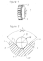
- FIG. 1 is a general view of a conical-shaped roller 1 represented in 3 dimensions with a view to 3/4, with groove 2 according to the present invention, which groove 2 is shaped to be able to drive welding wires 10 of different lower R-rays or equal to 1 mm.
- the roller 1 comprises a drive gear.
- Figure 2 is an enlarged view (in cross-section) of the area of the conical surface of the roller 1 of Figure 1 at the annular groove 2 in which passes the welding wire 10 (encircled area in Fig. 1).
- the annular groove 2 has a shape such that its cross-section by a plane diametral with respect to said roller 1 is formed of at least one first 3 and a second 4 straight sections forming with each other an angle A at less than 90 °.
- the first and second sections 3,4 are joined by a third section 5 in arc of a circle of arc R 'forming the bottom of the groove 2.
- the radius R 'of the third section 5 in an arc is chosen in function of the radius R of the wire 10 to be driven such that the ratio R '/ R ⁇ 0.85 is verified, in this case embodiment, so as to be able to use several wires of diameters (thus also of rays) without the need to replace the roller when passing from one wire to another.
- the roller 1 according to the invention thanks to the particular shape of the groove 2 and more specifically the groove bottom constituted by the third section 5, can be used with a wide range of welding wire, namely wires of a diameter typically ranging from 0.6 to 1.6 mm, or even beyond.
- Such a roller 1 is, in practice, the motor roller of a wire drive plate incorporated in a wire reel.
- a platinum usually has at least two rollers arranged vis-à-vis one with respect to the other so as to come to exert contact on the outer surface of the welding wire when the wire is inserted between rollers, namely a roller called “motor” and a roller called “presser”.
- the motor roller is movable in rotation about its axis so as to cause mechanically the welding wire according to a translational movement.
- the pressure roller is also rotatable about its axis, which axis is generally parallel to the axis of the motor roller, and has the function of going apply mechanical pressure to the outer surface of the wire, in a direction tending to the approach the motor roller, so as to hold the wire in contact with said motor roller and thus to allow an effective training of this one; the wire being sandwiched between the two rollers.
- means for setting roller in motion make it possible to confer a rotational movement about its axis to at least one of the rollers, preferably the motor roller.
- Such means of setting in motion typically comprise at least an electric motor cooperating with one or more gears and / or one or more axes drive the motor roller.
- the conical grooved roller of particular shape according to the invention is particularly suitable for incorporation into a welding wire feeding plate identical to that described by the aforementioned EP-A-1338370. However, it can also be used in plates of the type described in US-A-4,534,499 or in any other plate that can be incorporated into a welding wire drive.
- rollers according to the invention can equip both plates with 2 rollers (one motor, the other presser) that plates with 4 rollers (2 motors, 2 pressers).
- the roller 1 of the invention is made of a material of the treated steel type or similar.
- the groove 2 is preferably machined by means of one or more adapted tools, such as bar turning tools.
- a first roller G1 has been machined so as to have an arc radius R 'of approximately 0.24 mm (+/- 0.01 mm) and an angle A of about 90 °.
- This roller G1 allowed a drive effective of 3 wires of different diameters, namely diameters of 0.6 mm, 0.8 mm and 1 mm, which is equivalent to a ratio R '/ R of 0.5 to about 0.8, as the case may be.
- a second roller G2 has been machined so as to have an arc radius R 'of approximately 0.35 mm (+/- 0.01 mm) and an angle A of about 90 °.
- This G2 roller also allowed a effective training of 3 wires of different diameters, namely diameters of 1 mm, 1.2 mm and 1.6 mm, which equates to a ratio R '/ R of 0.44 to about 0.70, as the case may be.
Landscapes
- Engineering & Computer Science (AREA)
- Physics & Mathematics (AREA)
- Plasma & Fusion (AREA)
- Mechanical Engineering (AREA)
- Wire Processing (AREA)
- Forwarding And Storing Of Filamentary Material (AREA)
Abstract
Description
- le rapport suivant est vérifié : R' / R < 0.95, de préférence R' / R < 0.90.
- le rapport suivant est vérifié : R' / R < 0.85 ; utiliser un tel rapport inférieur à 0.85 étant considéré comme un mode préféré de réalisation de l'invention.
- le rayon R' de la troisième section est choisi en fonction du rayon R du fil tel que : R' / R ≤ 0.80, pour un fil à entraíner de rayon R inférieur à 0.9 mm.
- le rayon R' de la troisième section est choisi en fonction du rayon R du fil tel que : R' / R ≤ 0.80, pour un fil à entraíner de rayon R compris entre 0.3 mm et 0.8 mm.
- la première et la deuxième sections rectilignes forment l'une avec l'autre un angle A compris entre 90 et 120°, de préférence un angle de 90° à 100°.
- la troisième section en arc de cercle forme le fond de la gorge.
- elle comporte 2 ou 4 galets coniques, chaque galet moteur étant associé à un galet presseur.
Claims (10)
- Galet (1) de forme conique ou tronconique apte à entraíner un fil (10) de soudage de rayon R inférieur ou égal à 1 mm, comprenant une gorge (2) annulaire aménagée sur sa surface latérale conique (6), ladite gorge annulaire (2) ayant une forme telle que sa section droite par un plan diamétral par rapport audit galet (1) est formée d'au moins une première (3) et une deuxième (4) sections rectilignes formant l'une avec l'autre un angle (A) au moins égal à 90°, ces première et deuxième sections (3, 4) étant réunies par au moins une troisième section (5) en arc de cercle d'un rayon R', caractérisé en ce que le rayon R' de la troisième section (5) en arc de cercle est choisi en fonction du rayon R du fil (10) à entraíner tel que le rapport suivant soit vérifié : R' / R < 0.99
- Galet selon la revendication 1, caractérisé en ce que R' / R < 0.95, de préférence R' / R < 0.90.
- Galet selon l'une des revendications 1 ou 2, caractérisé en ce que R' / R < 0.85.
- Galet selon l'une des revendications 1 à 3, caractérisé en ce que le rayon R' de la troisième section est choisi en fonction du rayon R du fil tel que : R' / R ≤ 0.80, pour un fil à entraíner de rayon R inférieur à 0.9 mm, de préférence pour un fil à entraíner de rayon R compris entre 0.3 mm et 0.8 mm.
- Galet selon l'une des revendications 1 à 4, caractérisé en ce que la première et la deuxième sections rectilignes forment l'une avec l'autre un angle A compris entre 90 et 120 °, de préférence un angle de 90° à 100°.
- Platine de dévidage de fil de soudage dont les moyens d'entraínement du fil comprenant des galets rotatifs de forme conique, caractérisée en ce qu'au moins l'un desdits galets comporte une gorge ayant une forme selon l'une des revendications 1 à 5.
- Platine selon la revendication 6, caractérisée en ce que la troisième section (5) en arc de cercle forme le fond de la gorge (2).
- Platine selon l'une des revendications 6 ou 7, caractérisée en ce qu'elle comporte 2 ou 4 galets coniques, chaque galet moteur étant associé à un galet presseur.
- Dispositif de dévidage de fil de soudage comportant une platine selon l'une des revendications 6 à 8, en particulier un dévidoir de fil de soudage.
- Procédé de soudage à l'arc électrique avec fil d'apport fusible, dans lequel on met en oeuvre un dispositif selon la revendication 9 ou une platine selon l'une des revendications 6 à 8 pour alimenter une torche de soudage à l'arc avec ledit fil d'apport fusible, de préférence le fil d'apport fusible a un diamètre inférieur à 2 mm, de préférence encore entre environ 0.6 et 1.6 mm.
Applications Claiming Priority (2)
| Application Number | Priority Date | Filing Date | Title |
|---|---|---|---|
| FR0450533 | 2004-03-17 | ||
| FR0450533A FR2867711B1 (fr) | 2004-03-17 | 2004-03-17 | Galet conique a gorge pour platine de devidoir de fil de soudage |
Publications (2)
| Publication Number | Publication Date |
|---|---|
| EP1577245A2 true EP1577245A2 (fr) | 2005-09-21 |
| EP1577245A3 EP1577245A3 (fr) | 2006-10-25 |
Family
ID=34834281
Family Applications (1)
| Application Number | Title | Priority Date | Filing Date |
|---|---|---|---|
| EP05300116A Withdrawn EP1577245A3 (fr) | 2004-03-17 | 2005-02-14 | Galet conique à gorge pour platine de dévidoir de fil de soudage |
Country Status (2)
| Country | Link |
|---|---|
| EP (1) | EP1577245A3 (fr) |
| FR (1) | FR2867711B1 (fr) |
Cited By (10)
| Publication number | Priority date | Publication date | Assignee | Title |
|---|---|---|---|---|
| WO2008018961A1 (fr) * | 2006-08-10 | 2008-02-14 | Illinois Tool Works Inc. | Procédé et système d'alimentation de fil de soudage |
| FR2909911A1 (fr) * | 2006-12-15 | 2008-06-20 | Air Liquide Welding France Sa | Galet cylindrique a gorge amelioree pour platine de devidoir de fil de soudage |
| FR2932464A1 (fr) * | 2008-06-11 | 2009-12-18 | Air Liquide | Emballage a pre-decoupe et zone d'amorce pour bobine de fil de soudage |
| US9463524B2 (en) | 2012-06-14 | 2016-10-11 | Illinois Tool Works Inc. | System and method for adjusting feed roll position in a welding torch |
| US9931706B2 (en) | 2013-03-12 | 2018-04-03 | Illinois Tool Works Inc. | Adjustable drive shaft assembly |
| US10081072B2 (en) | 2011-03-29 | 2018-09-25 | Illinois Tool Works Inc. | Welding torch with wire feed speed control |
| US10239148B2 (en) | 2012-06-14 | 2019-03-26 | Illinois Tool Works Inc. | Motor assembly for a push-pull welding torch |
| US10632559B2 (en) | 2013-07-11 | 2020-04-28 | Illinois Tool Works Inc. | Indexing drive roll carrier system and method |
| US10675698B2 (en) | 2015-12-31 | 2020-06-09 | Illinois Tool Works Inc. | Wire delivery apparatus with a non-rotational actuator |
| US10730132B2 (en) | 2015-12-28 | 2020-08-04 | Illinois Tool Works Inc. | Reciprocating wire feed welding system and method |
Family Cites Families (4)
| Publication number | Priority date | Publication date | Assignee | Title |
|---|---|---|---|---|
| US3009619A (en) * | 1957-08-05 | 1961-11-21 | Air Reduction | Wire feed mechanism |
| US3022929A (en) * | 1959-03-17 | 1962-02-27 | Metal & Thermit Corp | Apparatus for moving slender elongated members lengthwise |
| FR2161481A5 (en) * | 1971-11-26 | 1973-07-06 | Soudure Autogene Francaise | Drive for multiple weld rods - ensures that rods of different dias are driven at the same linear speed from one motor |
| FR2697188B1 (fr) * | 1992-10-23 | 1995-01-27 | Amh Ltd | Dispositif d'entraînement de fil pour appareil à souder. |
-
2004
- 2004-03-17 FR FR0450533A patent/FR2867711B1/fr not_active Expired - Fee Related
-
2005
- 2005-02-14 EP EP05300116A patent/EP1577245A3/fr not_active Withdrawn
Cited By (17)
| Publication number | Priority date | Publication date | Assignee | Title |
|---|---|---|---|---|
| WO2008018961A1 (fr) * | 2006-08-10 | 2008-02-14 | Illinois Tool Works Inc. | Procédé et système d'alimentation de fil de soudage |
| US8575517B2 (en) | 2006-08-10 | 2013-11-05 | Illinois Tool Works Inc. | Welding wire feed system and method |
| US9050680B2 (en) | 2006-08-10 | 2015-06-09 | Illinois Tool Works Inc. | Welding wire feed system and method |
| US9333585B2 (en) | 2006-08-10 | 2016-05-10 | Illinois Tool Works, Inc. | Welding wire feed system and method |
| FR2909911A1 (fr) * | 2006-12-15 | 2008-06-20 | Air Liquide Welding France Sa | Galet cylindrique a gorge amelioree pour platine de devidoir de fil de soudage |
| FR2932464A1 (fr) * | 2008-06-11 | 2009-12-18 | Air Liquide | Emballage a pre-decoupe et zone d'amorce pour bobine de fil de soudage |
| US10081072B2 (en) | 2011-03-29 | 2018-09-25 | Illinois Tool Works Inc. | Welding torch with wire feed speed control |
| US9463524B2 (en) | 2012-06-14 | 2016-10-11 | Illinois Tool Works Inc. | System and method for adjusting feed roll position in a welding torch |
| US10239148B2 (en) | 2012-06-14 | 2019-03-26 | Illinois Tool Works Inc. | Motor assembly for a push-pull welding torch |
| US10632558B2 (en) | 2012-06-14 | 2020-04-28 | Illinois Tool Works Inc. | System and method for adjusting feed roll position in a welding torch |
| US11213909B2 (en) | 2012-06-14 | 2022-01-04 | Illinois Tool Works Inc. | Motor assembly for a push-pull welding torch |
| US9931706B2 (en) | 2013-03-12 | 2018-04-03 | Illinois Tool Works Inc. | Adjustable drive shaft assembly |
| US11173565B2 (en) | 2013-03-12 | 2021-11-16 | Illinois Tool Works Inc. | Adjustable drive shaft assembly |
| US10632559B2 (en) | 2013-07-11 | 2020-04-28 | Illinois Tool Works Inc. | Indexing drive roll carrier system and method |
| US10730132B2 (en) | 2015-12-28 | 2020-08-04 | Illinois Tool Works Inc. | Reciprocating wire feed welding system and method |
| US11969836B2 (en) | 2015-12-28 | 2024-04-30 | Illinois Tool Works Inc. | Reciprocating wire feed welding system and method |
| US10675698B2 (en) | 2015-12-31 | 2020-06-09 | Illinois Tool Works Inc. | Wire delivery apparatus with a non-rotational actuator |
Also Published As
| Publication number | Publication date |
|---|---|
| FR2867711A1 (fr) | 2005-09-23 |
| FR2867711B1 (fr) | 2006-09-08 |
| EP1577245A3 (fr) | 2006-10-25 |
Similar Documents
| Publication | Publication Date | Title |
|---|---|---|
| EP1577245A2 (fr) | Galet conique à gorge pour platine de dévidoir de fil de soudage | |
| EP0640435A1 (fr) | Machine à meuler | |
| FR2892983A1 (fr) | Armature de reglage de l'inclinaison du dossier d'un siege de vehicule automobile | |
| EP1784271B1 (fr) | Tete a aleser | |
| FR2929144A1 (fr) | Dispositif de coupe a la volee d'au moins un element filiforme entraine lineairement | |
| EP2331316B1 (fr) | Méthode et installation de construction d'une couche de fils d'armure | |
| EP0463936B1 (fr) | Appareil à épiler | |
| EP3771503B1 (fr) | Dispositif de cintrage | |
| FR2745805A1 (fr) | Machine a derouler des bobines en continu comportant au moins un moyen de deroulage de deux bobines jumelees ou coaxiales simultanement | |
| EP1401746A2 (fr) | Dispositif de transport de pieces pour l'alimentation de machines | |
| FR2909911A1 (fr) | Galet cylindrique a gorge amelioree pour platine de devidoir de fil de soudage | |
| FR2539120A1 (fr) | Dispositif pour distribuer des feuilles de papier a un mecanisme de comptage du nombre de feuilles de papier | |
| FR3023200A1 (fr) | Dispositif de devidage de fil de soudage avec reducteur de vitesse a engrenages epicycloidaux | |
| FR2807353A1 (fr) | Pince de ravitaillement pour machine-outil | |
| EP3048193B1 (fr) | Rouleau pour dispositif d'alimentation de fil | |
| EP1338370A2 (fr) | Platine de dévidage de fil de soudage a galets coniques | |
| WO2023274749A1 (fr) | Système d'essuyage d'une surface vitrée d'un véhicule | |
| EP4169648B1 (fr) | Tête de dépose d'une machine d'impression tridimensionnelle configurée pour déposer plusieurs fils simultanément et machine d'impression tridimensionnelle comportant ladite tête de dépose | |
| EP2363369A1 (fr) | Dispositif de bobinage | |
| FR2819737A1 (fr) | Appareil pour le broyage d'un materiau | |
| EP4433292B1 (fr) | Dispositif pour assembler les rayons d'un bandage pour roue au moyen de poussoirs qui sont actionnes et suspendus elastiquement par des leviers | |
| FR2811609A1 (fr) | Dispositif pour separer et introduire des bandes de matiere sur des trajets de transport de presses rotatives a imprimer | |
| FR2697188A1 (fr) | Dispositif d'entraînement de fil pour appareil à souder. | |
| BE1004875A5 (fr) | Dispositif de separation de cartes ou de formulaires pre-decoupes et formant une chaine. | |
| CH683599A5 (fr) | Machine à redresser le fil métallique. |
Legal Events
| Date | Code | Title | Description |
|---|---|---|---|
| PUAI | Public reference made under article 153(3) epc to a published international application that has entered the european phase |
Free format text: ORIGINAL CODE: 0009012 |
|
| AK | Designated contracting states |
Kind code of ref document: A2 Designated state(s): AT BE BG CH CY CZ DE DK EE ES FI FR GB GR HU IE IS IT LI LT LU MC NL PL PT RO SE SI SK TR |
|
| AX | Request for extension of the european patent |
Extension state: AL BA HR LV MK YU |
|
| PUAL | Search report despatched |
Free format text: ORIGINAL CODE: 0009013 |
|
| AK | Designated contracting states |
Kind code of ref document: A3 Designated state(s): AT BE BG CH CY CZ DE DK EE ES FI FR GB GR HU IE IS IT LI LT LU MC NL PL PT RO SE SI SK TR |
|
| AX | Request for extension of the european patent |
Extension state: AL BA HR LV MK YU |
|
| RAP1 | Party data changed (applicant data changed or rights of an application transferred) |
Owner name: AIR LIQUIDE WELDING FRANCE |
|
| 17P | Request for examination filed |
Effective date: 20070425 |
|
| AKX | Designation fees paid |
Designated state(s): AT BE BG CH CY CZ DE DK EE ES FI FR GB GR HU IE IS IT LI LT LU MC NL PL PT RO SE SI SK TR |
|
| STAA | Information on the status of an ep patent application or granted ep patent |
Free format text: STATUS: THE APPLICATION IS DEEMED TO BE WITHDRAWN |
|
| 18D | Application deemed to be withdrawn |
Effective date: 20110901 |