EP1577249A2 - Dispositif de surveillance de sécurité d'une cabine d'ascenseur - Google Patents
Dispositif de surveillance de sécurité d'une cabine d'ascenseur Download PDFInfo
- Publication number
- EP1577249A2 EP1577249A2 EP05002269A EP05002269A EP1577249A2 EP 1577249 A2 EP1577249 A2 EP 1577249A2 EP 05002269 A EP05002269 A EP 05002269A EP 05002269 A EP05002269 A EP 05002269A EP 1577249 A2 EP1577249 A2 EP 1577249A2
- Authority
- EP
- European Patent Office
- Prior art keywords
- elevator car
- elevator
- predetermined
- microprocessors
- speed
- Prior art date
- Legal status (The legal status is an assumption and is not a legal conclusion. Google has not performed a legal analysis and makes no representation as to the accuracy of the status listed.)
- Granted
Links
Images


Classifications
-
- B—PERFORMING OPERATIONS; TRANSPORTING
- B66—HOISTING; LIFTING; HAULING
- B66B—ELEVATORS; ESCALATORS OR MOVING WALKWAYS
- B66B5/00—Applications of checking, fault-correcting, or safety devices in elevators
- B66B5/02—Applications of checking, fault-correcting, or safety devices in elevators responsive to abnormal operating conditions
- B66B5/04—Applications of checking, fault-correcting, or safety devices in elevators responsive to abnormal operating conditions for detecting excessive speed
- B66B5/06—Applications of checking, fault-correcting, or safety devices in elevators responsive to abnormal operating conditions for detecting excessive speed electrical
Definitions
- the invention relates to a security monitoring device for a Elevator car.
- a device for delay control intended.
- the elevator shaft are located at the top of the pit and on the mechanical side Buffers that serve to decelerate the elevator car in an emergency.
- the speed of the elevator car a does not exceed the predetermined limit.
- the Braking device for the elevator car when the limit exceeded will be started soon enough for a sufficient deceleration, the takes place in accordance with a braking ramp, it can be done so that the buffer the Residual braking can take over.
- the device arranged for delay control at the appropriate location in the shaft electromechanical switch comprising, with a safety relay module coupled, and when they are reached in an elevator ride in the direction of Buffer and exceeding the limit for the speed Cab brakes triggered and simultaneously the drive is turned off.
- a device for retracting and if necessary to provide readjustments with open doors with a Bridging device for electromechanical door contacts that monitor whether the shaft door is closed.
- a Bridging device for electromechanical door contacts that monitor whether the shaft door is closed.
- Such mechanically based safety devices do not allow any continuous monitoring, but only a one-off.
- EP 0 694 792 B1 and EP 1 030 190 B1 is a Device for detecting the position of an elevator car is known, wherein in the Elevator shaft a sound signal conductor with predetermined, uniform Sound propagation speed is while the elevator car a Signal coupler for coupling a clocked sound signal in the Having sound signal conductor. At both ends of the sound signal conductor are Signal output coupler arranged with an evaluation unit for determining the Duration difference of the coupled-in sound signal from the coupling point to the signal extractors and for generating a for the current position of the Elevator car in the elevator shaft representative signal are connected.
- the object of the invention is to provide a security monitoring device for to create an elevator car that provides continuous safety monitoring allows.
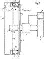
- Fig. 1 shows a block diagram of an elevator monitoring and control with a position detection device for an elevator car.
- FIG. 2 shows a block diagram of a security monitoring device for the elevator control of Fig. 1.
- Fig. 3 shows a velocity-time diagram as a motion profile for a Elevator car.
- a Position detection device for one along an elevator shaft A means a traction drive D movable elevator car 1 is the latter with a Signal coupler 2 provided, which serves to sound signals in a Sound signal conductor 3 with predetermined, uniform Sound propagation speed, which along the Elevator shaft extends. In both end regions of the sound signal conductor. 3 There is in each case a receiver unit 4a or 4b, which has a signal output coupler 5 and an evaluation unit 6 include. One of the evaluation units 6 supplies Trigger signals corresponding to a predetermined time grid to the signal coupler 2 of the elevator car 1, which is the coupling of a sound signal in the sound signal conductor 3 trigger, and to the other evaluation unit 6, so this also knows the respective triggering time.
- the signal coupler 2 both Evaluation 6 tell the time of coupling the sound signal, so that both evaluation units 6 each separately from the predetermined, uniform sound propagation velocity and signal transit time the Can calculate the position of the elevator car 1.
- the outputs 7a, 7b of the evaluation units 6 serve as inputs for a Safety monitoring device 8.
- the latter communicates with a Elevator control 9, via which the driving profile of the elevator car 1 is predetermined, and a safety circuit 10 for shutting off the elevator drive.
- the safety monitoring device 8 comprises two bushes 11, with to which the outputs 7a, 7b of the evaluation units 6 are connected. About one Interface 12, the position signals of the evaluation units 6, the corresponding the trigger signals are supplied in a predetermined time frame, respectively a microprocessor 13 a and 13 b given, for each one Power supply unit 14 is provided. The latter are connected to a network and connected to an emergency battery power supply 15 connected. At this dual-channel security monitoring, the microprocessors 13a communicate 13b for the purpose of mutual control over a line 16 with each other, whereby a crosswise data comparison, which also synchronizes the two Microprocessors 13a, 13b can be used.
- microprocessors 13a, 13b can be speed and acceleration and optionally one jerky movement of the elevator car 1 location dependent notice and currently compare with a given motion profile.
- an amplifier 18, which may also simultaneously as Comparator can act only to from both microprocessors 13a, 13b Maschinenminalten be present, the same output signals to be driven, the a safety relay stage 19 is actuated, the - in response to the microprocessors 13a, 13b - on the elevator control 9 and the safety circuit 10th acting with an appropriate jack 20 of the Safety monitoring device 8 is connected.
- Microprocessor 13a and 13b may optionally also have two interfaces 12 be provided to receive signals from different types of encoders to be able to process.
- a curve K1 is shown by way of example, which represents the driving profile of an elevator car 1 between two further floors, which is predetermined by the elevator control 9.
- the curve K1 has at the time of departure starting from a starting ramp up to a rated speed v nenn and from the latter to the arrival time a braking ramp.
- the curve K2, also shown by way of example in FIG. 3, is the driving profile between two closely adjacent storeys, the nominal speed vnom not being reached.
- the microprocessors 13a, 13b simultaneously or within a time window emit a corresponding signal which causes the traction drive to stop via the safety relay stage 19.
- a device for limiting the speed of the elevator car 1 is formed, which not only reacts to a predetermined exceeding of vnenn , but is a speed profile and thus more responsive.
- the safety monitoring device 8 can be used at the same time as a device for deceleration control, by then, if it is determined at a certain point in the elevator shaft A, that the current speed of the elevator car 1 a predetermined amount (not necessarily V nominal) exceeds, so that braking is no longer ensured by located in the elevator shaft a buffer, the microprocessors 13a, 13b leave the same time or within a time window, a corresponding signal to the safety relay stage 19 a stopping of the Travel drive and triggering the braking device causes. - As a result, smaller sized buffer can be used, or you can completely do without it.
- the security monitoring device 8 as a control for retractable with open doors usable.
- a request signal of a user are present from the elevator car 1 or from the corresponding floor, about via a socket 21 of the safety monitoring device 8 and an interface 22 is given to the microprocessors 13a, 13b. If the request signal arrives too late because the user has pressed the corresponding button too late, the speed is too high and the microprocessors 13a, 13b are not giving Bridging signal for the door contacts off, so that the doors open either can not be started before the standstill of the elevator car 1 or the Elevator car 1 even passes through.
- the security monitoring device 8 also for Creation of a virtual shelter on the head and / or pit side elevator shaft A, for example, when carrying out work in this Be used area, i. that at a corresponding request signal the route of the elevator car 1 is limited accordingly, so that a Intrusion into the virtual shelter is prevented.
- microprocessors 13a, 13b can also be used in Reference to the acceleration and the derivative thereof (the latter for evaluation of jerky movements).
- a diagnostic LED display 23 may be connected to the microprocessors 13a, 13b be coupled.
- the safety relay 19 can also have its own Power supply unit 24, in turn, from the microprocessors 13a, 13b is monitored.
- the respective position of the elevator car 1 is either from the position detection device via a line 25 or one of the Microprocessors 13 a, 13 b transmitted to the elevator controller 9.
- Over a Input device 26 in the form of a keyboard or the like. can the microprocessors 13a, 13b required data are entered. However, the data can also are received via the line 25 from the elevator controller 9.
- an output 28 may be present, which is the bottom flush of elevator car 1 and floor displays.
Landscapes
- Maintenance And Inspection Apparatuses For Elevators (AREA)
- Indicating And Signalling Devices For Elevators (AREA)
- Electric Propulsion And Braking For Vehicles (AREA)
- Forklifts And Lifting Vehicles (AREA)
Applications Claiming Priority (2)
| Application Number | Priority Date | Filing Date | Title |
|---|---|---|---|
| DE102004009250 | 2004-02-20 | ||
| DE102004009250A DE102004009250A1 (de) | 2004-02-20 | 2004-02-20 | Sicherheitsüberwachungseinrichtung für eine Aufzugskabine |
Publications (3)
| Publication Number | Publication Date |
|---|---|
| EP1577249A2 true EP1577249A2 (fr) | 2005-09-21 |
| EP1577249A3 EP1577249A3 (fr) | 2008-05-28 |
| EP1577249B1 EP1577249B1 (fr) | 2020-05-13 |
Family
ID=34833045
Family Applications (1)
| Application Number | Title | Priority Date | Filing Date |
|---|---|---|---|
| EP05002269.8A Expired - Lifetime EP1577249B1 (fr) | 2004-02-20 | 2005-02-03 | Dispositif de surveillance de sécurité d'une cabine d'ascenseur |
Country Status (7)
| Country | Link |
|---|---|
| US (1) | US7438158B2 (fr) |
| EP (1) | EP1577249B1 (fr) |
| JP (1) | JP2005231897A (fr) |
| CN (1) | CN100581972C (fr) |
| BR (1) | BRPI0500593A (fr) |
| CA (1) | CA2491806C (fr) |
| DE (1) | DE102004009250A1 (fr) |
Cited By (1)
| Publication number | Priority date | Publication date | Assignee | Title |
|---|---|---|---|---|
| EP3892579A1 (fr) * | 2020-04-06 | 2021-10-13 | Otis Elevator Company | Systèmes de sécurité d'ascenseur |
Families Citing this family (18)
| Publication number | Priority date | Publication date | Assignee | Title |
|---|---|---|---|---|
| DE10301504B3 (de) * | 2003-01-17 | 2004-10-21 | Phoenix Contact Gmbh & Co. Kg | Einsignalübertragung sicherer Prozessinformation |
| DE102004058756A1 (de) * | 2004-12-06 | 2006-06-14 | Siemens Ag | Geschwindigkeitsüberwachungsverfahren in einem Automatisierungssystem für eine Förderanlage |
| ATE371624T1 (de) * | 2005-01-07 | 2007-09-15 | Thyssen Krupp Aufzuege Gmbh | Aufzugsanlage mit einer steuervorrichtung |
| WO2008062500A1 (fr) * | 2006-11-20 | 2008-05-29 | Mitsubishi Electric Corporation | Système d'ascenseur |
| ES2475865T3 (es) | 2009-01-07 | 2014-07-11 | K. A. Schmersal Gmbh & Co. Kg | Método para supervisar la expansión de un foso de ascensor |
| DE102009037347A1 (de) * | 2009-08-14 | 2011-02-17 | K.A. Schmersal Holding Gmbh & Co. Kg | Elektronisches Sicherheitssystem für einen Aufzug |
| FI122598B (fi) * | 2011-04-01 | 2012-04-13 | Kone Corp | Menetelmä hissijärjestelmän toimintakunnon valvomiseksi |
| EP2594519A1 (fr) * | 2011-11-15 | 2013-05-22 | Inventio AG | Ascenseur doté d'un dispositif de sécurité |
| ES2619637T3 (es) * | 2012-10-30 | 2017-06-26 | Inventio Ag | Sistema de vigilancia del movimiento de una instalación de ascensor |
| WO2014131656A1 (fr) * | 2013-02-26 | 2014-09-04 | Kone Corporation | Test pour structure d'ascenseur |
| CN103818794B (zh) * | 2014-03-03 | 2016-06-08 | 中山市卓梅尼控制技术有限公司 | 防止电梯轿厢意外移动的保护装置 |
| DE102014113341A1 (de) * | 2014-09-16 | 2016-03-17 | Manfred Lienemann | Verfahren zum Betrieb einer Aufzuganlage und Aufzuganlage für Personen und/oder Lasten |
| DE102015211488A1 (de) * | 2015-06-22 | 2016-12-22 | Thyssenkrupp Ag | Sicherheitseinrichtung einer Aufzugsanlage |
| CN109155086A (zh) * | 2016-05-26 | 2019-01-04 | 三菱电机株式会社 | 出入管理系统 |
| EP3403967B1 (fr) * | 2017-05-15 | 2019-07-03 | KONE Corporation | Agencement de coupure de courant d'un ascenseur |
| JP7140634B2 (ja) * | 2018-10-30 | 2022-09-21 | 株式会社日立製作所 | エレベーターの制御システム |
| CN111204640B (zh) * | 2018-11-19 | 2021-04-23 | 赣州德业电子科技有限公司 | 一种监控设备及其使用方法 |
| CN112744658B (zh) * | 2020-12-18 | 2025-06-03 | 广东省特种设备检测研究院珠海检测院 | 电梯有载下行制动性能的无载荷测试系统 |
Family Cites Families (11)
| Publication number | Priority date | Publication date | Assignee | Title |
|---|---|---|---|---|
| US3902572A (en) * | 1973-11-28 | 1975-09-02 | Westinghouse Electric Corp | Elevator system |
| US5274203A (en) * | 1989-06-30 | 1993-12-28 | Otis Elevator Company | "Smart" position transducer system for elevators |
| CA2002409C (fr) | 1989-11-07 | 1995-03-14 | Klaus Katzy | Systeme de controle du fonctionnement d'une cage de puits de mine |
| DE4426793C1 (de) * | 1994-07-28 | 1995-10-26 | Schmersal K A Gmbh & Co | Einrichtung zur Positionserfassung |
| MY118747A (en) | 1995-11-08 | 2005-01-31 | Inventio Ag | Method and device for increased safety in elevators |
| US5883345A (en) * | 1997-12-23 | 1999-03-16 | Otis Elevator Company | Sonic position measurement system |
| DE19903644C1 (de) * | 1999-01-29 | 2000-07-06 | Schmersal K A Gmbh & Co | Einrichtung zur Positionserfassung |
| DE10146044A1 (de) | 2001-09-18 | 2003-04-03 | Militzer Otto Michael | Verfahren und Vorrichtung zur Kontrolle der Bewegungsabläufe bei Anlagen zur Personenbeförderung |
| JP4553535B2 (ja) * | 2001-09-28 | 2010-09-29 | 三菱電機株式会社 | エレベータ装置 |
| DE10150463A1 (de) * | 2001-10-16 | 2003-04-17 | Hcs Hydraulic Control Systems | Elektronische Einrichtung zur Regelung von Funktionen von hydraulischen und elektrischen Aufzügen |
| US7204347B2 (en) * | 2001-11-15 | 2007-04-17 | Otis Elevator Company | Arrhythmic pulse sequence for sonic distance measurement |
-
2004
- 2004-02-20 DE DE102004009250A patent/DE102004009250A1/de not_active Withdrawn
-
2005
- 2005-01-10 CA CA2491806A patent/CA2491806C/fr not_active Expired - Lifetime
- 2005-01-27 US US11/045,939 patent/US7438158B2/en active Active
- 2005-01-31 JP JP2005022952A patent/JP2005231897A/ja active Pending
- 2005-02-03 EP EP05002269.8A patent/EP1577249B1/fr not_active Expired - Lifetime
- 2005-02-07 CN CN200510008023A patent/CN100581972C/zh not_active Expired - Fee Related
- 2005-02-18 BR BR0500593-0A patent/BRPI0500593A/pt not_active Application Discontinuation
Cited By (1)
| Publication number | Priority date | Publication date | Assignee | Title |
|---|---|---|---|---|
| EP3892579A1 (fr) * | 2020-04-06 | 2021-10-13 | Otis Elevator Company | Systèmes de sécurité d'ascenseur |
Also Published As
| Publication number | Publication date |
|---|---|
| US7438158B2 (en) | 2008-10-21 |
| CA2491806C (fr) | 2011-05-31 |
| EP1577249A3 (fr) | 2008-05-28 |
| CN1657390A (zh) | 2005-08-24 |
| JP2005231897A (ja) | 2005-09-02 |
| CN100581972C (zh) | 2010-01-20 |
| US20050230191A1 (en) | 2005-10-20 |
| CA2491806A1 (fr) | 2005-08-20 |
| DE102004009250A1 (de) | 2005-09-08 |
| EP1577249B1 (fr) | 2020-05-13 |
| BRPI0500593A (pt) | 2005-10-04 |
Similar Documents
| Publication | Publication Date | Title |
|---|---|---|
| EP1577249B1 (fr) | Dispositif de surveillance de sécurité d'une cabine d'ascenseur | |
| DE112009004592B4 (de) | Aufzuganlage und Verfahren zum Überprüfen derselben | |
| EP2022742B1 (fr) | Système d'ascenseur | |
| DE102011054590B4 (de) | Vorrichtung zur Positionserfassung einer Aufzugkabine und Verfahren zum Betreiben einer Aufzuganlage | |
| EP1698580B1 (fr) | Système s'ascenseur | |
| EP1404603A1 (fr) | Installation d'ascenseur avec zone de protection virtuelle au niveau du fond et/ou du sommet de la cage d'ascenseur, et procede de commande de cette installation | |
| DE112013007449T5 (de) | Aufzugvorrichtung | |
| EP2367746A1 (fr) | Système d'ascenseur | |
| WO2013092274A1 (fr) | Dispositif de sécurité pour un ascenseur comprenant plusieurs cabines | |
| EP3310699A1 (fr) | Dispositif de sécurité d'une installation d'ascenseur | |
| AT523076B1 (de) | Seilbahnstation mit Sicherheitsschranke | |
| EP2457860A2 (fr) | Dispositif de sécurité pour ascenseur | |
| EP4267503A1 (fr) | Ascenseur, procédé de commande d'un ascenseur | |
| WO2021037912A1 (fr) | Système d'ascenseur qui fait passer une cabine dans un état de fonctionnement de sécurité en fonction d'un signal d'état de fermeture et d'une position de la cabine | |
| EP2319791A1 (fr) | Installation d'ascenseur | |
| EP2511218B1 (fr) | Procédé de surveillance de la dilatation d'une cage d'ascenseur | |
| EP1118574B1 (fr) | Installation d'ascenseur dont la cage présente une profondeur de fosse réduite | |
| EP1466853A1 (fr) | Méthode pour l' entretien d'un ascenseur | |
| EP3814264A1 (fr) | Panneau de commande de maintenance et commande d'ascenseur permettant de commander les déplacements d'une cabine d'ascenseur | |
| DE19833751A1 (de) | Verfahren und Vorrichtung zum Betrieb eines elektrisch betätigbaren Fahrzeugtürschlosses | |
| DE112017004022T5 (de) | Aufzugssystem | |
| WO2016096699A1 (fr) | Maintenance d'une installation d'ascenseur | |
| EP2463223B1 (fr) | Dispositif de contrôle de la position d'arrêt d'une cabine d'ascenseur | |
| DE102014113341A1 (de) | Verfahren zum Betrieb einer Aufzuganlage und Aufzuganlage für Personen und/oder Lasten | |
| EP1151953A1 (fr) | Dispositif d'évacuation des passagers d'un ascenseur |
Legal Events
| Date | Code | Title | Description |
|---|---|---|---|
| PUAI | Public reference made under article 153(3) epc to a published international application that has entered the european phase |
Free format text: ORIGINAL CODE: 0009012 |
|
| AK | Designated contracting states |
Kind code of ref document: A2 Designated state(s): AT BE BG CH CY CZ DE DK EE ES FI FR GB GR HU IE IS IT LI LT LU MC NL PL PT RO SE SI SK TR |
|
| AX | Request for extension of the european patent |
Extension state: AL BA HR LV MK YU |
|
| PUAL | Search report despatched |
Free format text: ORIGINAL CODE: 0009013 |
|
| AK | Designated contracting states |
Kind code of ref document: A3 Designated state(s): AT BE BG CH CY CZ DE DK EE ES FI FR GB GR HU IE IS IT LI LT LU MC NL PL PT RO SE SI SK TR |
|
| AX | Request for extension of the european patent |
Extension state: AL BA HR LV MK YU |
|
| 17P | Request for examination filed |
Effective date: 20080912 |
|
| AKX | Designation fees paid |
Designated state(s): DE FR GB IT |
|
| 17Q | First examination report despatched |
Effective date: 20170714 |
|
| GRAP | Despatch of communication of intention to grant a patent |
Free format text: ORIGINAL CODE: EPIDOSNIGR1 |
|
| INTG | Intention to grant announced |
Effective date: 20191219 |
|
| GRAS | Grant fee paid |
Free format text: ORIGINAL CODE: EPIDOSNIGR3 |
|
| GRAA | (expected) grant |
Free format text: ORIGINAL CODE: 0009210 |
|
| STAA | Information on the status of an ep patent application or granted ep patent |
Free format text: STATUS: THE PATENT HAS BEEN GRANTED |
|
| REG | Reference to a national code |
Ref country code: DE Ref legal event code: R081 Ref document number: 502005016137 Country of ref document: DE Owner name: K.A. SCHMERSAL HOLDING KG, DE Free format text: FORMER OWNER: K.A. SCHMERSAL HOLDING KG, 42279 WUPPERTAL, DE |
|
| AK | Designated contracting states |
Kind code of ref document: B1 Designated state(s): DE FR GB IT |
|
| REG | Reference to a national code |
Ref country code: GB Ref legal event code: FG4D Free format text: NOT ENGLISH |
|
| REG | Reference to a national code |
Ref country code: DE Ref legal event code: R096 Ref document number: 502005016137 Country of ref document: DE |
|
| REG | Reference to a national code |
Ref country code: DE Ref legal event code: R097 Ref document number: 502005016137 Country of ref document: DE |
|
| PLBE | No opposition filed within time limit |
Free format text: ORIGINAL CODE: 0009261 |
|
| STAA | Information on the status of an ep patent application or granted ep patent |
Free format text: STATUS: NO OPPOSITION FILED WITHIN TIME LIMIT |
|
| 26N | No opposition filed |
Effective date: 20210216 |
|
| PGFP | Annual fee paid to national office [announced via postgrant information from national office to epo] |
Ref country code: FR Payment date: 20230220 Year of fee payment: 19 |
|
| PGFP | Annual fee paid to national office [announced via postgrant information from national office to epo] |
Ref country code: IT Payment date: 20230223 Year of fee payment: 19 Ref country code: GB Payment date: 20230220 Year of fee payment: 19 |
|
| P01 | Opt-out of the competence of the unified patent court (upc) registered |
Effective date: 20230524 |
|
| PGFP | Annual fee paid to national office [announced via postgrant information from national office to epo] |
Ref country code: DE Payment date: 20240430 Year of fee payment: 20 |
|
| GBPC | Gb: european patent ceased through non-payment of renewal fee |
Effective date: 20240203 |
|
| PG25 | Lapsed in a contracting state [announced via postgrant information from national office to epo] |
Ref country code: GB Free format text: LAPSE BECAUSE OF NON-PAYMENT OF DUE FEES Effective date: 20240203 |
|
| PG25 | Lapsed in a contracting state [announced via postgrant information from national office to epo] |
Ref country code: FR Free format text: LAPSE BECAUSE OF NON-PAYMENT OF DUE FEES Effective date: 20240229 |
|
| PG25 | Lapsed in a contracting state [announced via postgrant information from national office to epo] |
Ref country code: GB Free format text: LAPSE BECAUSE OF NON-PAYMENT OF DUE FEES Effective date: 20240203 Ref country code: FR Free format text: LAPSE BECAUSE OF NON-PAYMENT OF DUE FEES Effective date: 20240229 |
|
| REG | Reference to a national code |
Ref country code: DE Ref legal event code: R071 Ref document number: 502005016137 Country of ref document: DE |
|
| PG25 | Lapsed in a contracting state [announced via postgrant information from national office to epo] |
Ref country code: IT Free format text: LAPSE BECAUSE OF NON-PAYMENT OF DUE FEES Effective date: 20240203 |