EP1577473A1 - Tür mit einem Bremsstopper - Google Patents
Tür mit einem Bremsstopper Download PDFInfo
- Publication number
- EP1577473A1 EP1577473A1 EP05450049A EP05450049A EP1577473A1 EP 1577473 A1 EP1577473 A1 EP 1577473A1 EP 05450049 A EP05450049 A EP 05450049A EP 05450049 A EP05450049 A EP 05450049A EP 1577473 A1 EP1577473 A1 EP 1577473A1
- Authority
- EP
- European Patent Office
- Prior art keywords
- door
- carrier
- floor
- brake element
- braking
- Prior art date
- Legal status (The legal status is an assumption and is not a legal conclusion. Google has not performed a legal analysis and makes no representation as to the accuracy of the status listed.)
- Granted
Links
Images


Classifications
-
- E—FIXED CONSTRUCTIONS
- E05—LOCKS; KEYS; WINDOW OR DOOR FITTINGS; SAFES
- E05C—BOLTS OR FASTENING DEVICES FOR WINGS, SPECIALLY FOR DOORS OR WINDOWS
- E05C17/00—Devices for holding wings open; Devices for limiting opening of wings or for holding wings open by a movable member extending between frame and wing; Braking devices, stops or buffers, combined therewith
- E05C17/02—Devices for holding wings open; Devices for limiting opening of wings or for holding wings open by a movable member extending between frame and wing; Braking devices, stops or buffers, combined therewith by mechanical means
- E05C17/44—Devices for holding wings open; Devices for limiting opening of wings or for holding wings open by a movable member extending between frame and wing; Braking devices, stops or buffers, combined therewith by mechanical means with a device carried on the wing for frictional or like engagement with a fixed flat surface, e.g. for holding wings open or closed by retractable feet
- E05C17/443—Devices for holding wings open; Devices for limiting opening of wings or for holding wings open by a movable member extending between frame and wing; Braking devices, stops or buffers, combined therewith by mechanical means with a device carried on the wing for frictional or like engagement with a fixed flat surface, e.g. for holding wings open or closed by retractable feet of the pivoted lever or eccentric type, e.g. for sliding windows
Definitions
- the invention relates to a door with a floor in the Door arranged brake element, which is adjustably guided in the door and over a actuated by the door movement actuator from a closed Door withdrawn basic position in his door open edge with the door open outstanding braking position isberichtwegbar.
- the actuator consists for example of a Sliding adjustable along the lower edge of the door pivoting adjustment the longitudinally immovable guided braking element and from a linkage to the linkage of the backdrop on the doorstep or on Floor (AT 407 892 B).
- This is achieved by an interaction of brake element and actuator the brake element as a function of the opening width the door from its basic position in its braking position or from his Brake position pivoted to the home position and thus the door either in braked the predetermined open position or released the movement of the door.
- the brake element and the actuator remain because of their arrangement in Bottom edge of the door largely invisible, especially since there is no on the ground or on a wall fixed stop there.
- the disadvantage is However, in this known device, the complex configuration of the Actuator in the form of a slotted guide, which requires a considerable amount of space has to make costly and cumbersome due to the linkage assemble is.
- a hitting doors on walls, home furnishings or other obstacles for example, by means of braking or stop elements made of rubber or plastic, which are on the ground, on a wall or to be attached to the furnishings.
- Brake stops are permanently mounted and therefore do not allow any variable limitation the opening angle of a door and complicate with their permanently mounted Stopper bodies a floor cleaning.
- the invention is therefore based on the object, a door of the beginning described type with a arranged in the bottom region of the door brake element to create, limiting their opening angle with the simplest possible Means is possible and which is characterized by its functional safety as well as their simple installation and design distinguishes.
- the actuator at least a arranged in the lower edge of the door, one end at one Door frame or on the floor spaced from the pivot axis of the door attacking pulling means comprises, the other end at a displacement device for stroke adjustment of the braking element perpendicular to the floor from his withdrawn basic position in his against the floor extended braking position attacks.
- the brake element in the lower edge of the door a safe function ensures the brake for the door movement. It only needs a recess for the displacement device for stroke adjustment of the brake element be provided for the door.
- the traction means can optionally in the range between the lower edge of the door and the floor or in one near the lower edge of the door provided groove from the displacement device to its point of application be led on the door floor or floor. It must therefore neither an elaborate slotted guide still provided the necessary elaborate adjustments are made.
- the brake element forms with the brake element preferably in any door usable, prefabricated unit that after making a corresponding recess retrofitted at any time in an existing door can be.
- a simple and little space requiring construction results itself, when the brake element mounted on a non-rotatably about its adjustment axis, but for stroke adjustment axially displaceable in the housing carrier is fixed and the displacement device for the carrier a the carrier depending on the opening angle of the door against the floor relocating Threaded drive includes.
- the brake element can in the carrier to a to the door lower edge parallel axis, preferably stop limited and against Spring force be mounted pivotally adjustable, which on the one hand a safe braking effect for the door in the braking area when opening the door results and on the other hand a slight closing of the door with little effort at any time is possible. This is especially the case when the brake element is formed eccentrically.
- a thread-shaped Nut comprises at its periphery supporting rotary body, wherein the groove interacts with a thread formed by the carrier and the traction means on a peripheral surface of the rotary body rope drum-like attacks.
- This in the groove engaging thread can at least one threaded pin be reduced.
- a door 1 according to the invention has a floor area of the door 1 arranged brake stopper 2 with a brake element 3, the adjustable in a arranged in the region of the lower door edge 4 housing 5 in the door first is guided.
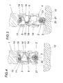
- the brake element 3 is by means of a door movement operated actuator in the form of a traction means 6 (a cable) from a with the door closed retracted basic position (Fig. 4) in his at opened door 1 the door lower edge 4 superior braking position justifywegbar.
- the traction means 6 is arranged in the region of the door lower edge 4 in a groove 7 and at one end on the door frame 8 by means of a screw 9 from the pivot axis 10 of the door 1 spaced apart and engages the other end of a displacement device 11 for stroke adjustment of the brake element 3 vertically against the floor 12 from its retracted into the door 1 basic position in his against the floor 12 extended braking position.
- the brake element 3 is non-rotatable at one about its adjustment axis 14 stored, but for stroke adjustment axially displaceable in the housing 5 carrier 13 attached.
- the displacement device 11 for the carrier 13 has a Carrier 13 in response to the opening or closing angle of the door 1 against the floor 12 displacing screw drive.
- the screw drive includes a rotatably mounted in the housing 5 about the adjustment axis 14 of the carrier 13, a thread-shaped groove 17 at its periphery supporting rotary body 16, wherein the groove 17 with a threaded pin 15 formed by the carrier 13 cooperates and the traction means 6 on a cylindrical portion of the Peripheral surface 18 of the rotary body 16 rope drum-like attacks.
- the rotary body 16 is relative to the housing 5 by means of a coil spring 19 such biased by spring force, that the coil spring 19 when closing the door. 1 for a provision of the brake element 3 from the braking position in his Basic position ensures while the traction means 6 on the cylindrical portion 18th of the rotary body 16 wound up like a drum pulley. Will the door out of its closed position pivoted in the open position, the traction means 6 winds from cylindrical portion 18 of the rotary body 16 and twisted while the Rotary body 16 in the housing 5, whereby the carrier 13 together with the brake element 3rd by means of the screw drive from his retracted into the door 1 basic position shifted in his against the floor 12 extended braking position becomes.
- the brake element 3 is in the carrier 13 at one to the lower door edge. 4 parallel axis 20 stop limited against the force of a spring 21 pivotally adjustable stored and according to the embodiment of FIGS. 1 to 4 formed eccentric, wherein the brake element 3 in its braking position (Fig. 3) has a floor 12 facing contact patch, the ensures, inter alia, that the open door 1 safely in its open position is held and a certain effort required to close the door is.
- a design variant of a brake element 3 is shown in FIG. 5.
- the brake element 3 could also only one in the carrier 13 used brake stopper be.
Landscapes
- Engineering & Computer Science (AREA)
- Mechanical Engineering (AREA)
- Braking Arrangements (AREA)
- Closing And Opening Devices For Wings, And Checks For Wings (AREA)
- Gates (AREA)
- Vehicle Step Arrangements And Article Storage (AREA)
- Refrigerator Housings (AREA)
- Power-Operated Mechanisms For Wings (AREA)
Abstract
Description
- Fig. 1
- eine erfindungsgemäße Tür mit einem Bremselement in teil geschnittener Vorderansicht,
- Fig. 2 und 3
- die Tür aus Fig. 1 im Schnitt nach der Linie II-II bzw. III-III,
- Fig. 4
- die Tür aus Fig. 1 bis 3 mit in seine Grundstellung zurückgezogenem Bremselement und
- Fig. 5
- eine Konstruktionsvariante eines Bremsstoppers.
Claims (7)
- Tür mit einem Bremsstopper, mit einem im Bodenbereich der Tür angeordneten Bremselement, das verstellbar in der Tür geführt und über einen durch die Türbewegung betätigten Stelltrieb aus einer bei geschlossener Tür zurückgezogenen Grundstellung in seine bei geöffneter Tür die Türunterkante überragende Bremsstellung vorbewegbar ist, dadurch gekennzeichnet, daß der Stelltrieb ein im Bereich der Türunterkante (4) angeordnetes, einerends an einem Türstock (8) oder am Fußboden von der Schwenkachse (10) der Tür (1) beabstandet angreifendens Zugmittel (6) umfaßt, das andernends an einer Verlagerungseinrichtung (11) zur Hubverstellung des Bremselementes (3) senkrecht gegen den Fußboden (12) aus seiner zurückgezogenen Grundstellung in seine gegen den Fußboden (12) ausgefahrene Bremsstellung angreift.
- Tür nach Anspruch 1, dadurch gekennzeichnet, daß das Bremselement (3) samt Verlagerungseinrichtung in einem Gehäuse (5) im Bereich der Türunterkante (4) angeordnet ist.
- Tür nach einem der Ansprüche 1 oder 2, dadurch gekennzeichnet, daß das Bremselement (3) mit Hilfe des Zugmittels (6) gegen Federkraft in Richtung seiner gegen den Fußboden (12) ausgefahrenen Bremsstellung verlagerbar ist.
- Tür nach einem der Ansprüche 2 oder 3, dadurch gekennzeichnet, daß das Bremselement (3) an einem um seine Verstellachse (14) drehfest gelagerten aber zur Hubverstellung axial im Gehäuse (5) verschiebbaren Träger (13) befestigt ist und die Verlagerungseinrichtung (11) für den Träger (13) einen den Träger (13) in Abhängigkeit vom Öffnungswinkel der Tür (1) gegen den Fußboden (12) verlagernden Gewindetrieb umfaßt.
- Tür nach Anspruch 4, dadurch gekennzeichnet, daß das Bremselement (3) im Träger (13) um eine zur Türunterkante (4) parallele Achse (20), vorzugsweise anschlagbegrenzt und gegen Federkraft schwenkvberstellbar gelagert ist.
- Tür nach Anspruch 5, dadurch gekennzeichnet, daß das Bremselement exzenterförmig ausgebildet ist.
- Tür nach einem der Ansprüche 4 bis 6, dadurch gekennzeichnet, daß der Gewindetrieb einen im Gehäuse (5) um die Verstellachse (14) des Trägers drehbar gelagerten, eine gewindeförmige Nut (17) an seinem Umfang tragenden Drehkörper (16) umfaßt, wobei die Nut (17) mit einem vom Träger (13) ausgebildeten Gewinde (15) zusammenwirkt und das Zugmittel an einer Umfangsfläche (18) des Drehkörpers (16) seiltrommelartig angreift.
Applications Claiming Priority (2)
| Application Number | Priority Date | Filing Date | Title |
|---|---|---|---|
| AT0045104A AT501872B1 (de) | 2004-03-15 | 2004-03-15 | Tür mit einem bremsstopper |
| AT4512004 | 2004-03-15 |
Publications (2)
| Publication Number | Publication Date |
|---|---|
| EP1577473A1 true EP1577473A1 (de) | 2005-09-21 |
| EP1577473B1 EP1577473B1 (de) | 2008-01-16 |
Family
ID=34831636
Family Applications (1)
| Application Number | Title | Priority Date | Filing Date |
|---|---|---|---|
| EP05450049A Expired - Lifetime EP1577473B1 (de) | 2004-03-15 | 2005-03-15 | Tür mit einem Bremsstopper |
Country Status (3)
| Country | Link |
|---|---|
| EP (1) | EP1577473B1 (de) |
| AT (2) | AT501872B1 (de) |
| DE (1) | DE502005002535D1 (de) |
Cited By (2)
| Publication number | Priority date | Publication date | Assignee | Title |
|---|---|---|---|---|
| GB2466431A (en) * | 2008-12-16 | 2010-06-23 | Simon Peter Charles Westacott | A door security brake having a tapered belt to apply a braking force against a floor engaging roller |
| CN111411854A (zh) * | 2020-03-04 | 2020-07-14 | 徐丽萍 | 门吸分离开关组件及其门吸 |
Citations (4)
| Publication number | Priority date | Publication date | Assignee | Title |
|---|---|---|---|---|
| DE253610C (de) * | ||||
| US1375388A (en) * | 1919-11-14 | 1921-04-19 | Haralson Waldo | Door-stop |
| WO1992003630A1 (en) * | 1990-08-28 | 1992-03-05 | Bernard Arthur Rear | Device for restricting the movements of doors |
| AT407892B (de) * | 1999-05-26 | 2001-07-25 | Josef Stierberger | Bremsstopper für türen |
Family Cites Families (2)
| Publication number | Priority date | Publication date | Assignee | Title |
|---|---|---|---|---|
| DE336865C (de) * | 1921-05-14 | Heinrich J Bolten | Vorrichtung zur Unterstuetzung und Feststellung von Klapptuerfluegeln | |
| US2493292A (en) * | 1948-06-22 | 1950-01-03 | Ralph V Jenkins | Doorstop |
-
2004
- 2004-03-15 AT AT0045104A patent/AT501872B1/de not_active IP Right Cessation
-
2005
- 2005-03-15 EP EP05450049A patent/EP1577473B1/de not_active Expired - Lifetime
- 2005-03-15 AT AT05450049T patent/ATE384185T1/de not_active IP Right Cessation
- 2005-03-15 DE DE502005002535T patent/DE502005002535D1/de not_active Expired - Fee Related
Patent Citations (4)
| Publication number | Priority date | Publication date | Assignee | Title |
|---|---|---|---|---|
| DE253610C (de) * | ||||
| US1375388A (en) * | 1919-11-14 | 1921-04-19 | Haralson Waldo | Door-stop |
| WO1992003630A1 (en) * | 1990-08-28 | 1992-03-05 | Bernard Arthur Rear | Device for restricting the movements of doors |
| AT407892B (de) * | 1999-05-26 | 2001-07-25 | Josef Stierberger | Bremsstopper für türen |
Cited By (3)
| Publication number | Priority date | Publication date | Assignee | Title |
|---|---|---|---|---|
| GB2466431A (en) * | 2008-12-16 | 2010-06-23 | Simon Peter Charles Westacott | A door security brake having a tapered belt to apply a braking force against a floor engaging roller |
| GB2466431B (en) * | 2008-12-16 | 2011-05-04 | Simon Peter Charles Westacott | A door security brake |
| CN111411854A (zh) * | 2020-03-04 | 2020-07-14 | 徐丽萍 | 门吸分离开关组件及其门吸 |
Also Published As
| Publication number | Publication date |
|---|---|
| ATE384185T1 (de) | 2008-02-15 |
| AT501872A1 (de) | 2006-12-15 |
| EP1577473B1 (de) | 2008-01-16 |
| DE502005002535D1 (de) | 2008-03-06 |
| AT501872B1 (de) | 2007-03-15 |
Similar Documents
| Publication | Publication Date | Title |
|---|---|---|
| EP3452681B1 (de) | Dichtungsvorrichtung für eine schiebetür | |
| EP1485556B1 (de) | Schloss | |
| EP1929116A1 (de) | Sperrelement, insbesondere für eine durchgangssperre zur personendurchgangskontrolle | |
| DE102012009500B4 (de) | Schiebetür | |
| DE202007004845U1 (de) | Teleskopansatz für Rolladenachse | |
| DE102010007128B4 (de) | Dämpfungseinrichtung für schienengeführte Türelemente sowie Verwendung einer derartigen Dämpfungseinrichtung | |
| DE102005013742A1 (de) | Gerät zum synchronen Aus- und Einfahren von zwei Drahtabschnitten | |
| EP1564360B1 (de) | Vorrichtung zum motorischen Öffnen und Schliessen eines Karosserieteils | |
| EP1223299A2 (de) | Rollo, insbesondere Insektenschutz-Rollo | |
| DE19707607C2 (de) | Einrichtung mit einem verstellbaren Organ zum Schutz gegen Licht und/oder Witterung und/oder Einbruch und/oder zum Umlenken von Licht | |
| EP1577473B1 (de) | Tür mit einem Bremsstopper | |
| EP3667010A1 (de) | Anschlagvorrichtung für eine automatische türdichtung, insbesondere für eine pivot- oder pendeltür, anordnung aus einer automatischen türdichtung und einer anschlagvorrichtung | |
| EP2476845B1 (de) | Öffnungsfolgesteuerungseinrichtung einer zweiflügeligen tür | |
| DE10107461C2 (de) | Schließfolgeregler | |
| DE60027078T2 (de) | Vorrichtung zum Blockieren von aufrollbaren Vorhängen und dergleichen | |
| DE102012221558B4 (de) | Antrieb für einen Flügel einer Tür oder eines Fensters | |
| DE102011000295A1 (de) | Vorrichtung zum automatischen Schließen oder Öffnen einer Schiebetür | |
| AT502965B1 (de) | Vorrichtung zur regelung der öffnungsfolge von zweiflügeligen schwenktüren | |
| DE102024136127B3 (de) | Schließeinrichtung für eine Schiebetür, insbesondere eine Insektenschutztür | |
| DE8516303U1 (de) | Jalousierbarer Rolladen | |
| WO2002064927A1 (de) | Schliessfolgeregler | |
| EP1156181A2 (de) | Band für Türen, Fenster und dergleichen | |
| AT407892B (de) | Bremsstopper für türen | |
| DE202007008728U1 (de) | Türstopper mit Drehgriffbestätigung | |
| DE102008025600B3 (de) | Kassettenmarkise mit Kippgelenken |
Legal Events
| Date | Code | Title | Description |
|---|---|---|---|
| PUAI | Public reference made under article 153(3) epc to a published international application that has entered the european phase |
Free format text: ORIGINAL CODE: 0009012 |
|
| AK | Designated contracting states |
Kind code of ref document: A1 Designated state(s): AT BE BG CH CY CZ DE DK EE ES FI FR GB GR HU IE IS IT LI LT LU MC NL PL PT RO SE SI SK TR |
|
| AX | Request for extension of the european patent |
Extension state: AL BA HR LV MK YU |
|
| 17P | Request for examination filed |
Effective date: 20060221 |
|
| AKX | Designation fees paid |
Designated state(s): AT BE BG CH CY CZ DE DK EE ES FI FR GB GR HU IE IS IT LI LT LU MC NL PL PT RO SE SI SK TR |
|
| GRAP | Despatch of communication of intention to grant a patent |
Free format text: ORIGINAL CODE: EPIDOSNIGR1 |
|
| GRAS | Grant fee paid |
Free format text: ORIGINAL CODE: EPIDOSNIGR3 |
|
| GRAA | (expected) grant |
Free format text: ORIGINAL CODE: 0009210 |
|
| AK | Designated contracting states |
Kind code of ref document: B1 Designated state(s): AT BE BG CH CY CZ DE DK EE ES FI FR GB GR HU IE IS IT LI LT LU MC NL PL PT RO SE SI SK TR |
|
| REG | Reference to a national code |
Ref country code: GB Ref legal event code: FG4D |
|
| REG | Reference to a national code |
Ref country code: CH Ref legal event code: EP |
|
| REG | Reference to a national code |
Ref country code: IE Ref legal event code: FG4D Free format text: LANGUAGE OF EP DOCUMENT: GERMAN |
|
| REF | Corresponds to: |
Ref document number: 502005002535 Country of ref document: DE Date of ref document: 20080306 Kind code of ref document: P |
|
| PG25 | Lapsed in a contracting state [announced via postgrant information from national office to epo] |
Ref country code: NL Free format text: LAPSE BECAUSE OF FAILURE TO SUBMIT A TRANSLATION OF THE DESCRIPTION OR TO PAY THE FEE WITHIN THE PRESCRIBED TIME-LIMIT Effective date: 20080116 |
|
| NLV1 | Nl: lapsed or annulled due to failure to fulfill the requirements of art. 29p and 29m of the patents act | ||
| PG25 | Lapsed in a contracting state [announced via postgrant information from national office to epo] |
Ref country code: LT Free format text: LAPSE BECAUSE OF FAILURE TO SUBMIT A TRANSLATION OF THE DESCRIPTION OR TO PAY THE FEE WITHIN THE PRESCRIBED TIME-LIMIT Effective date: 20080116 Ref country code: IS Free format text: LAPSE BECAUSE OF FAILURE TO SUBMIT A TRANSLATION OF THE DESCRIPTION OR TO PAY THE FEE WITHIN THE PRESCRIBED TIME-LIMIT Effective date: 20080516 Ref country code: FI Free format text: LAPSE BECAUSE OF FAILURE TO SUBMIT A TRANSLATION OF THE DESCRIPTION OR TO PAY THE FEE WITHIN THE PRESCRIBED TIME-LIMIT Effective date: 20080116 Ref country code: ES Free format text: LAPSE BECAUSE OF FAILURE TO SUBMIT A TRANSLATION OF THE DESCRIPTION OR TO PAY THE FEE WITHIN THE PRESCRIBED TIME-LIMIT Effective date: 20080427 |
|
| GBV | Gb: ep patent (uk) treated as always having been void in accordance with gb section 77(7)/1977 [no translation filed] | ||
| ET | Fr: translation filed | ||
| PG25 | Lapsed in a contracting state [announced via postgrant information from national office to epo] |
Ref country code: BG Free format text: LAPSE BECAUSE OF FAILURE TO SUBMIT A TRANSLATION OF THE DESCRIPTION OR TO PAY THE FEE WITHIN THE PRESCRIBED TIME-LIMIT Effective date: 20080416 |
|
| BERE | Be: lapsed |
Owner name: STIERBERGER, JOSEF Effective date: 20080331 |
|
| PG25 | Lapsed in a contracting state [announced via postgrant information from national office to epo] |
Ref country code: PL Free format text: LAPSE BECAUSE OF FAILURE TO SUBMIT A TRANSLATION OF THE DESCRIPTION OR TO PAY THE FEE WITHIN THE PRESCRIBED TIME-LIMIT Effective date: 20080116 Ref country code: SI Free format text: LAPSE BECAUSE OF FAILURE TO SUBMIT A TRANSLATION OF THE DESCRIPTION OR TO PAY THE FEE WITHIN THE PRESCRIBED TIME-LIMIT Effective date: 20080116 Ref country code: PT Free format text: LAPSE BECAUSE OF FAILURE TO SUBMIT A TRANSLATION OF THE DESCRIPTION OR TO PAY THE FEE WITHIN THE PRESCRIBED TIME-LIMIT Effective date: 20080616 |
|
| REG | Reference to a national code |
Ref country code: IE Ref legal event code: FD4D |
|
| PG25 | Lapsed in a contracting state [announced via postgrant information from national office to epo] |
Ref country code: IE Free format text: LAPSE BECAUSE OF FAILURE TO SUBMIT A TRANSLATION OF THE DESCRIPTION OR TO PAY THE FEE WITHIN THE PRESCRIBED TIME-LIMIT Effective date: 20080116 Ref country code: DK Free format text: LAPSE BECAUSE OF FAILURE TO SUBMIT A TRANSLATION OF THE DESCRIPTION OR TO PAY THE FEE WITHIN THE PRESCRIBED TIME-LIMIT Effective date: 20080116 Ref country code: SE Free format text: LAPSE BECAUSE OF FAILURE TO SUBMIT A TRANSLATION OF THE DESCRIPTION OR TO PAY THE FEE WITHIN THE PRESCRIBED TIME-LIMIT Effective date: 20080416 Ref country code: SK Free format text: LAPSE BECAUSE OF FAILURE TO SUBMIT A TRANSLATION OF THE DESCRIPTION OR TO PAY THE FEE WITHIN THE PRESCRIBED TIME-LIMIT Effective date: 20080116 Ref country code: MC Free format text: LAPSE BECAUSE OF NON-PAYMENT OF DUE FEES Effective date: 20080331 Ref country code: CZ Free format text: LAPSE BECAUSE OF FAILURE TO SUBMIT A TRANSLATION OF THE DESCRIPTION OR TO PAY THE FEE WITHIN THE PRESCRIBED TIME-LIMIT Effective date: 20080116 |
|
| PLBE | No opposition filed within time limit |
Free format text: ORIGINAL CODE: 0009261 |
|
| STAA | Information on the status of an ep patent application or granted ep patent |
Free format text: STATUS: NO OPPOSITION FILED WITHIN TIME LIMIT |
|
| PG25 | Lapsed in a contracting state [announced via postgrant information from national office to epo] |
Ref country code: RO Free format text: LAPSE BECAUSE OF FAILURE TO SUBMIT A TRANSLATION OF THE DESCRIPTION OR TO PAY THE FEE WITHIN THE PRESCRIBED TIME-LIMIT Effective date: 20080116 |
|
| 26N | No opposition filed |
Effective date: 20081017 |
|
| PG25 | Lapsed in a contracting state [announced via postgrant information from national office to epo] |
Ref country code: GB Free format text: LAPSE BECAUSE OF FAILURE TO SUBMIT A TRANSLATION OF THE DESCRIPTION OR TO PAY THE FEE WITHIN THE PRESCRIBED TIME-LIMIT Effective date: 20080116 |
|
| PG25 | Lapsed in a contracting state [announced via postgrant information from national office to epo] |
Ref country code: EE Free format text: LAPSE BECAUSE OF FAILURE TO SUBMIT A TRANSLATION OF THE DESCRIPTION OR TO PAY THE FEE WITHIN THE PRESCRIBED TIME-LIMIT Effective date: 20080116 |
|
| PG25 | Lapsed in a contracting state [announced via postgrant information from national office to epo] |
Ref country code: BE Free format text: LAPSE BECAUSE OF NON-PAYMENT OF DUE FEES Effective date: 20080331 |
|
| PG25 | Lapsed in a contracting state [announced via postgrant information from national office to epo] |
Ref country code: CY Free format text: LAPSE BECAUSE OF FAILURE TO SUBMIT A TRANSLATION OF THE DESCRIPTION OR TO PAY THE FEE WITHIN THE PRESCRIBED TIME-LIMIT Effective date: 20080116 |
|
| PG25 | Lapsed in a contracting state [announced via postgrant information from national office to epo] |
Ref country code: AT Free format text: LAPSE BECAUSE OF NON-PAYMENT OF DUE FEES Effective date: 20080315 |
|
| PGFP | Annual fee paid to national office [announced via postgrant information from national office to epo] |
Ref country code: DE Payment date: 20090529 Year of fee payment: 5 Ref country code: FR Payment date: 20090327 Year of fee payment: 5 Ref country code: IT Payment date: 20090326 Year of fee payment: 5 |
|
| REG | Reference to a national code |
Ref country code: CH Ref legal event code: PL |
|
| PG25 | Lapsed in a contracting state [announced via postgrant information from national office to epo] |
Ref country code: LI Free format text: LAPSE BECAUSE OF NON-PAYMENT OF DUE FEES Effective date: 20090331 Ref country code: CH Free format text: LAPSE BECAUSE OF NON-PAYMENT OF DUE FEES Effective date: 20090331 |
|
| PG25 | Lapsed in a contracting state [announced via postgrant information from national office to epo] |
Ref country code: LU Free format text: LAPSE BECAUSE OF NON-PAYMENT OF DUE FEES Effective date: 20080315 Ref country code: HU Free format text: LAPSE BECAUSE OF FAILURE TO SUBMIT A TRANSLATION OF THE DESCRIPTION OR TO PAY THE FEE WITHIN THE PRESCRIBED TIME-LIMIT Effective date: 20080717 |
|
| PG25 | Lapsed in a contracting state [announced via postgrant information from national office to epo] |
Ref country code: TR Free format text: LAPSE BECAUSE OF FAILURE TO SUBMIT A TRANSLATION OF THE DESCRIPTION OR TO PAY THE FEE WITHIN THE PRESCRIBED TIME-LIMIT Effective date: 20080116 |
|
| PG25 | Lapsed in a contracting state [announced via postgrant information from national office to epo] |
Ref country code: GR Free format text: LAPSE BECAUSE OF FAILURE TO SUBMIT A TRANSLATION OF THE DESCRIPTION OR TO PAY THE FEE WITHIN THE PRESCRIBED TIME-LIMIT Effective date: 20080417 |
|
| REG | Reference to a national code |
Ref country code: FR Ref legal event code: ST Effective date: 20101130 |
|
| PG25 | Lapsed in a contracting state [announced via postgrant information from national office to epo] |
Ref country code: FR Free format text: LAPSE BECAUSE OF NON-PAYMENT OF DUE FEES Effective date: 20100331 |
|
| PG25 | Lapsed in a contracting state [announced via postgrant information from national office to epo] |
Ref country code: DE Free format text: LAPSE BECAUSE OF NON-PAYMENT OF DUE FEES Effective date: 20101001 |
|
| PG25 | Lapsed in a contracting state [announced via postgrant information from national office to epo] |
Ref country code: IT Free format text: LAPSE BECAUSE OF NON-PAYMENT OF DUE FEES Effective date: 20100315 |