EP1577501A1 - Hochdruckturbinenstator einer Strömungsmaschine und deren Zusammenbauverfahren - Google Patents
Hochdruckturbinenstator einer Strömungsmaschine und deren Zusammenbauverfahren Download PDFInfo
- Publication number
- EP1577501A1 EP1577501A1 EP05290319A EP05290319A EP1577501A1 EP 1577501 A1 EP1577501 A1 EP 1577501A1 EP 05290319 A EP05290319 A EP 05290319A EP 05290319 A EP05290319 A EP 05290319A EP 1577501 A1 EP1577501 A1 EP 1577501A1
- Authority
- EP
- European Patent Office
- Prior art keywords
- stator
- housing
- pressure turbine
- sectors
- air
- Prior art date
- Legal status (The legal status is an assumption and is not a legal conclusion. Google has not performed a legal analysis and makes no representation as to the accuracy of the status listed.)
- Granted
Links
- 238000000034 method Methods 0.000 title claims abstract description 19
- 125000006850 spacer group Chemical group 0.000 claims abstract description 22
- 230000003252 repetitive effect Effects 0.000 description 4
- 238000002485 combustion reaction Methods 0.000 description 1
- 230000008602 contraction Effects 0.000 description 1
- 230000001627 detrimental effect Effects 0.000 description 1
- 230000000694 effects Effects 0.000 description 1
- 239000007789 gas Substances 0.000 description 1
Images



Classifications
-
- F—MECHANICAL ENGINEERING; LIGHTING; HEATING; WEAPONS; BLASTING
- F01—MACHINES OR ENGINES IN GENERAL; ENGINE PLANTS IN GENERAL; STEAM ENGINES
- F01D—NON-POSITIVE DISPLACEMENT MACHINES OR ENGINES, e.g. STEAM TURBINES
- F01D9/00—Stators
- F01D9/02—Nozzles; Nozzle boxes; Stator blades; Guide conduits, e.g. individual nozzles
- F01D9/04—Nozzles; Nozzle boxes; Stator blades; Guide conduits, e.g. individual nozzles forming ring or sector
- F01D9/042—Nozzles; Nozzle boxes; Stator blades; Guide conduits, e.g. individual nozzles forming ring or sector fixing blades to stators
-
- F—MECHANICAL ENGINEERING; LIGHTING; HEATING; WEAPONS; BLASTING
- F01—MACHINES OR ENGINES IN GENERAL; ENGINE PLANTS IN GENERAL; STEAM ENGINES
- F01D—NON-POSITIVE DISPLACEMENT MACHINES OR ENGINES, e.g. STEAM TURBINES
- F01D25/00—Component parts, details, or accessories, not provided for in, or of interest apart from, other groups
- F01D25/24—Casings; Casing parts, e.g. diaphragms, casing fastenings
- F01D25/246—Fastening of diaphragms or stator-rings
-
- F—MECHANICAL ENGINEERING; LIGHTING; HEATING; WEAPONS; BLASTING
- F01—MACHINES OR ENGINES IN GENERAL; ENGINE PLANTS IN GENERAL; STEAM ENGINES
- F01D—NON-POSITIVE DISPLACEMENT MACHINES OR ENGINES, e.g. STEAM TURBINES
- F01D25/00—Component parts, details, or accessories, not provided for in, or of interest apart from, other groups
- F01D25/24—Casings; Casing parts, e.g. diaphragms, casing fastenings
- F01D25/26—Double casings; Measures against temperature strain in casings
-
- F—MECHANICAL ENGINEERING; LIGHTING; HEATING; WEAPONS; BLASTING
- F05—INDEXING SCHEMES RELATING TO ENGINES OR PUMPS IN VARIOUS SUBCLASSES OF CLASSES F01-F04
- F05D—INDEXING SCHEME FOR ASPECTS RELATING TO NON-POSITIVE-DISPLACEMENT MACHINES OR ENGINES, GAS-TURBINES OR JET-PROPULSION PLANTS
- F05D2260/00—Function
- F05D2260/20—Heat transfer, e.g. cooling
- F05D2260/209—Heat transfer, e.g. cooling using vortex tubes
Definitions
- the present invention relates to the general field of driving game at the top of the moving blades of a high-pressure turbine turbomachine. It is more particularly a method of the sectorized elements composing the stator of a turbine high-pressure turbomachine.
- the stator of a turbomachine high-pressure turbine is consists mainly of an annular housing arranged around an axis longitudinal axis of the turbine, a plurality of sectorized spacers mounted on the housing and a plurality of ring segments attached to the spacers and which form a circular surface surrounding blades movable rotor of the turbine.
- the present invention therefore aims to overcome such drawbacks by proposing a method of assembling the sectorized elements of a annular stator of a high-pressure turbine which makes it possible to obtain a gameplay at the top of the blades leading to distortions as low as possible and in all repetitive cases.
- the invention relates to a method of assembly of sectorized elements of an annular stator of a high-pressure turbine turbomachine about a longitudinal axis of said turbine, characterized in that it consists in defining an angular distribution pattern of the elements of the stator for a predetermined angular sector, the distribution pattern being defined to avoid radial alignment between inter-sector areas stator elements defined between two adjacent sectors the same stator element, and to repeat the distribution pattern over any the circumference of the stator.
- the angular distribution pattern is repeated from symmetrical way in rotation with respect to the angular sector predetermined.
- the stator elements consist of a housing annular, of a plurality of sectorized spacers on which are fixed a plurality of ring sectors forming a circular surface continuous flow around turbine blades of a turbine rotor, and a plurality of angular sectors of air flow boxes intended to unload air on the housing to allow the control of the game in top of the rotor blades of the high-pressure turbine
- the motive angular distribution of the stator elements is advantageously defined to avoid radial alignment between inter-spacing zones defined between two adjacent spacers and inter-sector areas housing defined between two adjacent housing sectors.
- the method further consists in radially aligning each feed mouth with air with an inter-sector box area.
- the predetermined angular sector corresponds to an angular sector of air circulation housing.
- each angular sector of air circulation box is associated advantageously three spacers and an air supply mouth.
- the invention also relates to a high-pressure turbine stator whose angular distribution of the sectored elements leads to low and repetitive thermal distortions.
- the high-pressure turbine stator is characterized in that the stator elements are angularly distributed around the longitudinal axis of the high-pressure turbine so as to avoid radial alignment between inter-spacer zones defined between two adjacent spacers and inter-sector box areas defined between two housing sectors adjacent.
- stator elements are distributed angularly around the longitudinal axis of the high-pressure turbine in in addition to radially align each air supply mouth with an inter-sector box area.
- the stator comprises N angular sectors air flow boxes, 3N spacers, N power outlets in air and 6N ring sectors.
- the stator 10 of a high-pressure turbine comprises a housing annular 12 disposed around a longitudinal axis X-X of the high-pressure turbine.
- annular housing 12 On the inner surface of the annular housing 12 are mounted a plurality of sectorized spacers 14 and arranged circumferentially around the longitudinal axis X-X of the turbine.
- sectored elements for the rest of the description, it is understood that the designated elements are present in the form of angular sectors which, when placed end to end, form an annular assembly.
- Ring sectors 16 are fixed on the inner surface of the spacers 14.
- the ring sectors 16 are arranged circumferentially around the longitudinal axis X-X of the turbine and form a continuous circular surface surrounding moving blades (no shown in the figures) of a rotor (not shown) of the turbine high pressure.
- the inner surface of the ring sectors 16 partially defines the flow of gases from the combustion chamber (no represented) of the turbomachine and passing through the high-pressure turbine.
- a game (not shown) is left between the inner surface of the ring sectors 16 and the top of the rotor blades of the rotor of the turbine to allow rotation of the latter.
- a device is 18.
- This device consists in particular of a tube air collector 20 disposed around the housing 12 and supplied with air by the least one supply line 22 (only one is shown on the figure 1).
- the air collection tube 20 supplies an air with a plurality of angular sectors of air circulation boxes 24 which are fixed circumferentially on the casing 12 via rules of Fixing 26.
- the supply of air circulation housing sectors 24 is carried out by means of waterproof V-clamps 28 connected to the collecting tube 20.
- each housing sector 24 consists of three air circulation ramps spaced axially and substantially parallel to each other. Each of these ramps is pierced with a plurality of holes (not shown) that discharge air on the housing 14 to change the temperature.
- a plurality of air supply vents 30 are disposed through the housing 12. These mouths 30 are intended for supplying air to a stage of a low-pressure distributor (not shown in the figures) of the turbomachine arranged downstream of the high-pressure turbine.
- the invention provides a method of assembling these different stator elements of the turbine about its longitudinal axis X-X.
- this method consists in defining an angular distribution pattern of the stator elements 10 for a predetermined angular sector ⁇ , and in repeating the pattern over the entire circumference of the stator.
- the pattern of distribution of the elements of the stator 10 over a predetermined angular sector ⁇ is defined so as to avoid radial alignment between inter-sector areas of stator elements.
- the inter-sector zones are defined as zones located between two adjacent sectors of the same element of the stator.
- the predetermined angular sector ⁇ is advantageously chosen so as to correspond to an angular sector of housing 24.
- FIG. 2 illustrates an example of application of the method according to the invention.
- the predetermined angular sector ⁇ a has a sector of 60 °.
- stator elements 10 are arranged so as to avoid radial alignment between inter-sector areas of stator elements. More particularly, the angular distribution is chosen so as to avoid radial alignment between the inter-spacing zones 14a defined between two adjacent struts 14 and the inter-sector areas 24a of housing defined between two housing sectors 24 adjacent.
- Such a distribution of the spacers 14 with respect to the sectors housing 24 avoids radially aligning between areas of the 12 on which air is not discharged by the device of game control 18 (that is to say at the level of inter-sector zones 24a of housing) and inter-spacing zones 14a.
- the distribution pattern thus defined on the angular sector ⁇ a is then repeated over the entire circumference of the stator 10.
- the distribution pattern is repeated five times to cover the entire circumference of the stator.
- the distribution pattern is repeated over the entire circumference of the stator symmetrically in rotation with respect to the predetermined angular sector ⁇ a .
- the temperature distribution of the housing 12 is done so symmetrical around the entire circumference of the housing.
- thermal distortions of the housing 12 are substantially repetitive, which facilitates control.
- the angular distribution pattern of the stator elements 10 for the sector predetermined angle is also defined to align radially each air supply mouth 30 with an inter-sectoral area housing 24a.
- This particular arrangement of mouths air supply 30 also contributes to improving the homogeneity of crankcase temperature 12.
- the mouths 30 intended to to supply air a stage of a low-pressure distributor are each disposed between two housing sectors 24 adjacent.
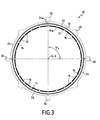
- FIG. 3 illustrates another example of application of the method according to the invention.
- the selected angular sector ⁇ b has a sector of 90 °.
- This angular sector ⁇ b corresponds to an angular sector of housing 24.
- the elements of the stator 10 are arranged, on the one hand so as to avoid radial alignment between inter-sector areas of stator elements, and on the other hand so as to radially align each mouth of the stator. air supply 30 with an inter-sector housing area 24a.
- FIG. 4 illustrates another example of application of the method according to the invention.
- ⁇ c a sector of 30 ° corresponding to an angular sector of housing 24.
- each angular sector of housing of air circulation 24 is associated three spacers 14 and a mouth 30.
- the high-pressure turbine stator 10 comprises N angular sectors of air flow boxes 24, 3N spacers 14, N air supply vents 30, and 6N sectors of ring 16.
Landscapes
- Engineering & Computer Science (AREA)
- Mechanical Engineering (AREA)
- General Engineering & Computer Science (AREA)
- Turbine Rotor Nozzle Sealing (AREA)
Applications Claiming Priority (2)
| Application Number | Priority Date | Filing Date | Title |
|---|---|---|---|
| FR0402825A FR2867805A1 (fr) | 2004-03-18 | 2004-03-18 | Stator de turbine haute-pression de turbomachine et procede d'assemblage |
| FR0402825 | 2004-03-18 |
Publications (2)
| Publication Number | Publication Date |
|---|---|
| EP1577501A1 true EP1577501A1 (de) | 2005-09-21 |
| EP1577501B1 EP1577501B1 (de) | 2006-11-29 |
Family
ID=34834195
Family Applications (1)
| Application Number | Title | Priority Date | Filing Date |
|---|---|---|---|
| EP05290319A Expired - Lifetime EP1577501B1 (de) | 2004-03-18 | 2005-02-14 | Hochdruckturbinenstator einer Strömungsmaschine und deren Zusammenbauverfahren |
Country Status (9)
| Country | Link |
|---|---|
| US (1) | US7360987B2 (de) |
| EP (1) | EP1577501B1 (de) |
| JP (1) | JP4526420B2 (de) |
| CA (1) | CA2500493C (de) |
| DE (1) | DE602005000290T2 (de) |
| ES (1) | ES2273318T3 (de) |
| FR (1) | FR2867805A1 (de) |
| RU (1) | RU2374459C2 (de) |
| UA (1) | UA87968C2 (de) |
Cited By (1)
| Publication number | Priority date | Publication date | Assignee | Title |
|---|---|---|---|---|
| EP2182175A3 (de) * | 2008-10-30 | 2013-10-09 | General Electric Company | Gehäusestruktur und Verfahren zur Verbesserung des thermischen Verhaltens der Turbine während transienter und stationärer Betriebsbedingungen |
Families Citing this family (3)
| Publication number | Priority date | Publication date | Assignee | Title |
|---|---|---|---|---|
| DE102009031009A1 (de) * | 2009-06-29 | 2010-12-30 | Osram Opto Semiconductors Gmbh | Strahlungsemittierendes Bauelement |
| DE102015215144B4 (de) | 2015-08-07 | 2017-11-09 | MTU Aero Engines AG | Vorrichtung und Verfahren zum Beeinflussen der Temperaturen in Innenringsegmenten einer Gasturbine |
| US10443616B2 (en) * | 2016-03-16 | 2019-10-15 | United Technologies Corporation | Blade outer air seal with centrally mounted seal arc segments |
Citations (6)
| Publication number | Priority date | Publication date | Assignee | Title |
|---|---|---|---|---|
| US3146992A (en) * | 1962-12-10 | 1964-09-01 | Gen Electric | Turbine shroud support structure |
| EP0892153A1 (de) * | 1997-07-18 | 1999-01-20 | Societe Nationale D'etude Et De Construction De Moteurs D'aviation "Snecma" | Heiz- b.z.w. Kühleinrichtung für ein Gehäuse mit kreisförmigem Querschnitt |
| EP0892152A1 (de) * | 1997-07-18 | 1999-01-20 | Societe Nationale D'etude Et De Construction De Moteurs D'aviation "Snecma" | Heiz- b.z.w. Kühleinrichtung für ein Gehäuse mit kreisförmigem Querschnitt |
| EP1205637A1 (de) * | 2000-11-09 | 2002-05-15 | Snecma Moteurs | Kühlungsvorrichtung für einen Statorring |
| EP1258599A2 (de) * | 2001-03-23 | 2002-11-20 | General Electric Company | Montageverfahren und Vorrichtung zur Aufrechterhaltung des Schaufelspitzenspiels einer Rotoranordnung |
| US20040018084A1 (en) * | 2002-05-10 | 2004-01-29 | Halliwell Mark A. | Gas turbine blade tip clearance control structure |
Family Cites Families (4)
| Publication number | Priority date | Publication date | Assignee | Title |
|---|---|---|---|---|
| US5100291A (en) * | 1990-03-28 | 1992-03-31 | General Electric Company | Impingement manifold |
| US5281085A (en) * | 1990-12-21 | 1994-01-25 | General Electric Company | Clearance control system for separately expanding or contracting individual portions of an annular shroud |
| US5205115A (en) * | 1991-11-04 | 1993-04-27 | General Electric Company | Gas turbine engine case counterflow thermal control |
| US5219268A (en) * | 1992-03-06 | 1993-06-15 | General Electric Company | Gas turbine engine case thermal control flange |
-
2004
- 2004-03-18 FR FR0402825A patent/FR2867805A1/fr active Pending
-
2005
- 2005-02-14 ES ES05290319T patent/ES2273318T3/es not_active Expired - Lifetime
- 2005-02-14 EP EP05290319A patent/EP1577501B1/de not_active Expired - Lifetime
- 2005-02-14 DE DE602005000290T patent/DE602005000290T2/de not_active Expired - Lifetime
- 2005-03-04 CA CA2500493A patent/CA2500493C/fr not_active Expired - Lifetime
- 2005-03-07 US US11/072,280 patent/US7360987B2/en active Active
- 2005-03-11 JP JP2005068906A patent/JP4526420B2/ja not_active Expired - Lifetime
- 2005-03-14 RU RU2005106888/06A patent/RU2374459C2/ru active
- 2005-03-18 UA UAA200502480A patent/UA87968C2/ru unknown
Patent Citations (6)
| Publication number | Priority date | Publication date | Assignee | Title |
|---|---|---|---|---|
| US3146992A (en) * | 1962-12-10 | 1964-09-01 | Gen Electric | Turbine shroud support structure |
| EP0892153A1 (de) * | 1997-07-18 | 1999-01-20 | Societe Nationale D'etude Et De Construction De Moteurs D'aviation "Snecma" | Heiz- b.z.w. Kühleinrichtung für ein Gehäuse mit kreisförmigem Querschnitt |
| EP0892152A1 (de) * | 1997-07-18 | 1999-01-20 | Societe Nationale D'etude Et De Construction De Moteurs D'aviation "Snecma" | Heiz- b.z.w. Kühleinrichtung für ein Gehäuse mit kreisförmigem Querschnitt |
| EP1205637A1 (de) * | 2000-11-09 | 2002-05-15 | Snecma Moteurs | Kühlungsvorrichtung für einen Statorring |
| EP1258599A2 (de) * | 2001-03-23 | 2002-11-20 | General Electric Company | Montageverfahren und Vorrichtung zur Aufrechterhaltung des Schaufelspitzenspiels einer Rotoranordnung |
| US20040018084A1 (en) * | 2002-05-10 | 2004-01-29 | Halliwell Mark A. | Gas turbine blade tip clearance control structure |
Cited By (1)
| Publication number | Priority date | Publication date | Assignee | Title |
|---|---|---|---|---|
| EP2182175A3 (de) * | 2008-10-30 | 2013-10-09 | General Electric Company | Gehäusestruktur und Verfahren zur Verbesserung des thermischen Verhaltens der Turbine während transienter und stationärer Betriebsbedingungen |
Also Published As
| Publication number | Publication date |
|---|---|
| DE602005000290D1 (de) | 2007-01-11 |
| US7360987B2 (en) | 2008-04-22 |
| US20050238477A1 (en) | 2005-10-27 |
| CA2500493A1 (fr) | 2005-09-18 |
| ES2273318T3 (es) | 2007-05-01 |
| FR2867805A1 (fr) | 2005-09-23 |
| UA87968C2 (ru) | 2009-09-10 |
| JP4526420B2 (ja) | 2010-08-18 |
| JP2005264935A (ja) | 2005-09-29 |
| EP1577501B1 (de) | 2006-11-29 |
| CA2500493C (fr) | 2012-01-10 |
| RU2005106888A (ru) | 2006-08-20 |
| RU2374459C2 (ru) | 2009-11-27 |
| DE602005000290T2 (de) | 2007-06-21 |
Similar Documents
| Publication | Publication Date | Title |
|---|---|---|
| CA2500491C (fr) | Dispositif de pilotage de jeu de turbine a gaz a equilibrage des debits d'air | |
| EP1505261B1 (de) | Vorrichtung für die Regelung von Spalten in einer Gasturbine | |
| CA2491666C (fr) | Perfectionnements apportes au dispositif de controle de jeu dans une turbine a gaz | |
| EP1775427B1 (de) | Vorrichtung zur Regelung des Spiels zwischen einem Rotorblatt und einem feststehendem Ring in einer Gasturbine | |
| EP2009234B1 (de) | Kühlvorrichtung der Hohlräume einer Rotorscheibe einer Strömungsmaschine | |
| EP0176447B1 (de) | Vorrichtung für die automatische Regelung des Spiels einer Labyrinthdichtung einer Turbomaschine | |
| EP3587743B1 (de) | Vorrichtung zum kühlen eines turbotriebwerkgehäuses | |
| FR2699223A1 (fr) | Dispositif réglable de guidage d'écoulement. | |
| EP2300688B1 (de) | Hochdruckturbine für turbomotor mit verbesserter befestigung des gehäuses zur steuerung des radialspiels beweglicher schaufeln | |
| EP3130765A1 (de) | Enteisender trennungsschnabel eines kompressors einer axialen turbomaschine | |
| EP1637702B1 (de) | Turbinenmodule für einen Gasturbinenmotor | |
| EP3781791A1 (de) | Turbinendüse für einen turbinenmotor mit einem passiven system zum wiedereinführen von blow-by-gas in einen gasstrahl | |
| FR2527268A1 (fr) | Prediffuseur pour un moteur a turbine a gaz | |
| EP1452691B1 (de) | Ringförmige Leitschaufelplattform einer Niederdruckstufe einer Gasturbine | |
| CA2500493C (fr) | Stator de turbine haute-pression de turbomachine et procede d'assemblage | |
| FR3006366A1 (fr) | Roue de turbine dans une turbomachine | |
| WO2023047034A1 (fr) | Turbine à gaz haute-pression pour une turbomachine et turbomachine | |
| EP4136327B1 (de) | Kühlvorrichtung für turbinengehäuse | |
| EP3320186B1 (de) | Anordnung einer gasturbine | |
| WO2024194568A1 (fr) | Architecture pour joint d'etancheite de turbomachine | |
| FR3039225A1 (fr) | Turbomachine, telle par exemple qu'un turboreacteur d'avion | |
| EP4409113A1 (de) | Hochdruckgasturbine für eine turbomaschine und turbomaschine | |
| FR3121469A1 (fr) | Ensemble d’anneau de turbine pour une turbomachine | |
| FR3118782A1 (fr) | Turbine a gaz haute-pression pour turbomachine | |
| FR3097271A1 (fr) | Dispositif de refroidissement d’un carter d’une turbomachine |
Legal Events
| Date | Code | Title | Description |
|---|---|---|---|
| PUAI | Public reference made under article 153(3) epc to a published international application that has entered the european phase |
Free format text: ORIGINAL CODE: 0009012 |
|
| 17P | Request for examination filed |
Effective date: 20050222 |
|
| AK | Designated contracting states |
Kind code of ref document: A1 Designated state(s): AT BE BG CH CY CZ DE DK EE ES FI FR GB GR HU IE IS IT LI LT LU MC NL PL PT RO SE SI SK TR |
|
| AX | Request for extension of the european patent |
Extension state: AL BA HR LV MK YU |
|
| GRAP | Despatch of communication of intention to grant a patent |
Free format text: ORIGINAL CODE: EPIDOSNIGR1 |
|
| AKX | Designation fees paid |
Designated state(s): DE ES FR GB IT SE |
|
| GRAS | Grant fee paid |
Free format text: ORIGINAL CODE: EPIDOSNIGR3 |
|
| GRAA | (expected) grant |
Free format text: ORIGINAL CODE: 0009210 |
|
| AK | Designated contracting states |
Kind code of ref document: B1 Designated state(s): DE ES FR GB IT SE |
|
| PG25 | Lapsed in a contracting state [announced via postgrant information from national office to epo] |
Ref country code: IT Free format text: LAPSE BECAUSE OF FAILURE TO SUBMIT A TRANSLATION OF THE DESCRIPTION OR TO PAY THE FEE WITHIN THE PRESCRIBED TIME-LIMIT;WARNING: LAPSES OF ITALIAN PATENTS WITH EFFECTIVE DATE BEFORE 2007 MAY HAVE OCCURRED AT ANY TIME BEFORE 2007. THE CORRECT EFFECTIVE DATE MAY BE DIFFERENT FROM THE ONE RECORDED. Effective date: 20061129 |
|
| REG | Reference to a national code |
Ref country code: GB Ref legal event code: FG4D Free format text: NOT ENGLISH |
|
| REG | Reference to a national code |
Ref country code: SE Ref legal event code: TRGR |
|
| REF | Corresponds to: |
Ref document number: 602005000290 Country of ref document: DE Date of ref document: 20070111 Kind code of ref document: P |
|
| GBT | Gb: translation of ep patent filed (gb section 77(6)(a)/1977) |
Effective date: 20070124 |
|
| REG | Reference to a national code |
Ref country code: ES Ref legal event code: FG2A Ref document number: 2273318 Country of ref document: ES Kind code of ref document: T3 |
|
| PLBE | No opposition filed within time limit |
Free format text: ORIGINAL CODE: 0009261 |
|
| STAA | Information on the status of an ep patent application or granted ep patent |
Free format text: STATUS: NO OPPOSITION FILED WITHIN TIME LIMIT |
|
| 26N | No opposition filed |
Effective date: 20070830 |
|
| PGRI | Patent reinstated in contracting state [announced from national office to epo] |
Ref country code: IT Effective date: 20090401 |
|
| PGFP | Annual fee paid to national office [announced via postgrant information from national office to epo] |
Ref country code: ES Payment date: 20130207 Year of fee payment: 9 |
|
| REG | Reference to a national code |
Ref country code: ES Ref legal event code: FD2A Effective date: 20150401 |
|
| PG25 | Lapsed in a contracting state [announced via postgrant information from national office to epo] |
Ref country code: ES Free format text: LAPSE BECAUSE OF NON-PAYMENT OF DUE FEES Effective date: 20140215 |
|
| REG | Reference to a national code |
Ref country code: FR Ref legal event code: PLFP Year of fee payment: 12 |
|
| REG | Reference to a national code |
Ref country code: FR Ref legal event code: PLFP Year of fee payment: 13 |
|
| REG | Reference to a national code |
Ref country code: FR Ref legal event code: CD Owner name: SAFRAN AIRCRAFT ENGINES Effective date: 20170717 |
|
| REG | Reference to a national code |
Ref country code: FR Ref legal event code: PLFP Year of fee payment: 14 |
|
| REG | Reference to a national code |
Ref country code: DE Ref legal event code: R082 Ref document number: 602005000290 Country of ref document: DE Representative=s name: CBDL PATENTANWAELTE GBR, DE |
|
| PGFP | Annual fee paid to national office [announced via postgrant information from national office to epo] |
Ref country code: DE Payment date: 20240123 Year of fee payment: 20 Ref country code: GB Payment date: 20240123 Year of fee payment: 20 |
|
| PGFP | Annual fee paid to national office [announced via postgrant information from national office to epo] |
Ref country code: SE Payment date: 20240123 Year of fee payment: 20 Ref country code: IT Payment date: 20240123 Year of fee payment: 20 Ref country code: FR Payment date: 20240123 Year of fee payment: 20 |
|
| REG | Reference to a national code |
Ref country code: DE Ref legal event code: R071 Ref document number: 602005000290 Country of ref document: DE |
|
| REG | Reference to a national code |
Ref country code: GB Ref legal event code: PE20 Expiry date: 20250213 |
|
| REG | Reference to a national code |
Ref country code: SE Ref legal event code: EUG |
|
| PG25 | Lapsed in a contracting state [announced via postgrant information from national office to epo] |
Ref country code: GB Free format text: LAPSE BECAUSE OF EXPIRATION OF PROTECTION Effective date: 20250213 |