EP1577516A1 - Wärmeschild für Abgaskrümmer und Katalysator - Google Patents
Wärmeschild für Abgaskrümmer und Katalysator Download PDFInfo
- Publication number
- EP1577516A1 EP1577516A1 EP05250987A EP05250987A EP1577516A1 EP 1577516 A1 EP1577516 A1 EP 1577516A1 EP 05250987 A EP05250987 A EP 05250987A EP 05250987 A EP05250987 A EP 05250987A EP 1577516 A1 EP1577516 A1 EP 1577516A1
- Authority
- EP
- European Patent Office
- Prior art keywords
- catalyst
- exhaust manifold
- heat shield
- heat
- shield member
- Prior art date
- Legal status (The legal status is an assumption and is not a legal conclusion. Google has not performed a legal analysis and makes no representation as to the accuracy of the status listed.)
- Granted
Links
Images




Classifications
-
- F—MECHANICAL ENGINEERING; LIGHTING; HEATING; WEAPONS; BLASTING
- F01—MACHINES OR ENGINES IN GENERAL; ENGINE PLANTS IN GENERAL; STEAM ENGINES
- F01N—GAS-FLOW SILENCERS OR EXHAUST APPARATUS FOR MACHINES OR ENGINES IN GENERAL; GAS-FLOW SILENCERS OR EXHAUST APPARATUS FOR INTERNAL-COMBUSTION ENGINES
- F01N13/00—Exhaust or silencing apparatus characterised by constructional features
- F01N13/08—Other arrangements or adaptations of exhaust conduits
- F01N13/10—Other arrangements or adaptations of exhaust conduits of exhaust manifolds
- F01N13/102—Other arrangements or adaptations of exhaust conduits of exhaust manifolds having thermal insulation
-
- F—MECHANICAL ENGINEERING; LIGHTING; HEATING; WEAPONS; BLASTING
- F01—MACHINES OR ENGINES IN GENERAL; ENGINE PLANTS IN GENERAL; STEAM ENGINES
- F01N—GAS-FLOW SILENCERS OR EXHAUST APPARATUS FOR MACHINES OR ENGINES IN GENERAL; GAS-FLOW SILENCERS OR EXHAUST APPARATUS FOR INTERNAL-COMBUSTION ENGINES
- F01N13/00—Exhaust or silencing apparatus characterised by constructional features
- F01N13/18—Construction facilitating manufacture, assembly, or disassembly
- F01N13/1805—Fixing exhaust manifolds, exhaust pipes or pipe sections to each other, to engine or to vehicle body
- F01N13/1811—Fixing exhaust manifolds, exhaust pipes or pipe sections to each other, to engine or to vehicle body with means permitting relative movement, e.g. compensation of thermal expansion or vibration
-
- F—MECHANICAL ENGINEERING; LIGHTING; HEATING; WEAPONS; BLASTING
- F01—MACHINES OR ENGINES IN GENERAL; ENGINE PLANTS IN GENERAL; STEAM ENGINES
- F01N—GAS-FLOW SILENCERS OR EXHAUST APPARATUS FOR MACHINES OR ENGINES IN GENERAL; GAS-FLOW SILENCERS OR EXHAUST APPARATUS FOR INTERNAL-COMBUSTION ENGINES
- F01N3/00—Exhaust or silencing apparatus having means for purifying, rendering innocuous, or otherwise treating exhaust
- F01N3/08—Exhaust or silencing apparatus having means for purifying, rendering innocuous, or otherwise treating exhaust for rendering innocuous
-
- F—MECHANICAL ENGINEERING; LIGHTING; HEATING; WEAPONS; BLASTING
- F01—MACHINES OR ENGINES IN GENERAL; ENGINE PLANTS IN GENERAL; STEAM ENGINES
- F01N—GAS-FLOW SILENCERS OR EXHAUST APPARATUS FOR MACHINES OR ENGINES IN GENERAL; GAS-FLOW SILENCERS OR EXHAUST APPARATUS FOR INTERNAL-COMBUSTION ENGINES
- F01N3/00—Exhaust or silencing apparatus having means for purifying, rendering innocuous, or otherwise treating exhaust
- F01N3/08—Exhaust or silencing apparatus having means for purifying, rendering innocuous, or otherwise treating exhaust for rendering innocuous
- F01N3/10—Exhaust or silencing apparatus having means for purifying, rendering innocuous, or otherwise treating exhaust for rendering innocuous by thermal or catalytic conversion of noxious components of exhaust
- F01N3/24—Exhaust or silencing apparatus having means for purifying, rendering innocuous, or otherwise treating exhaust for rendering innocuous by thermal or catalytic conversion of noxious components of exhaust characterised by constructional aspects of converting apparatus
-
- F—MECHANICAL ENGINEERING; LIGHTING; HEATING; WEAPONS; BLASTING
- F01—MACHINES OR ENGINES IN GENERAL; ENGINE PLANTS IN GENERAL; STEAM ENGINES
- F01N—GAS-FLOW SILENCERS OR EXHAUST APPARATUS FOR MACHINES OR ENGINES IN GENERAL; GAS-FLOW SILENCERS OR EXHAUST APPARATUS FOR INTERNAL-COMBUSTION ENGINES
- F01N2450/00—Methods or apparatus for fitting, inserting or repairing different elements
- F01N2450/20—Methods or apparatus for fitting, inserting or repairing different elements by mechanical joints, e.g. by deforming housing, tube, baffle plate or parts thereof
-
- Y—GENERAL TAGGING OF NEW TECHNOLOGICAL DEVELOPMENTS; GENERAL TAGGING OF CROSS-SECTIONAL TECHNOLOGIES SPANNING OVER SEVERAL SECTIONS OF THE IPC; TECHNICAL SUBJECTS COVERED BY FORMER USPC CROSS-REFERENCE ART COLLECTIONS [XRACs] AND DIGESTS
- Y02—TECHNOLOGIES OR APPLICATIONS FOR MITIGATION OR ADAPTATION AGAINST CLIMATE CHANGE
- Y02A—TECHNOLOGIES FOR ADAPTATION TO CLIMATE CHANGE
- Y02A50/00—TECHNOLOGIES FOR ADAPTATION TO CLIMATE CHANGE in human health protection, e.g. against extreme weather
- Y02A50/20—Air quality improvement or preservation, e.g. vehicle emission control or emission reduction by using catalytic converters
-
- Y—GENERAL TAGGING OF NEW TECHNOLOGICAL DEVELOPMENTS; GENERAL TAGGING OF CROSS-SECTIONAL TECHNOLOGIES SPANNING OVER SEVERAL SECTIONS OF THE IPC; TECHNICAL SUBJECTS COVERED BY FORMER USPC CROSS-REFERENCE ART COLLECTIONS [XRACs] AND DIGESTS
- Y10—TECHNICAL SUBJECTS COVERED BY FORMER USPC
- Y10S—TECHNICAL SUBJECTS COVERED BY FORMER USPC CROSS-REFERENCE ART COLLECTIONS [XRACs] AND DIGESTS
- Y10S165/00—Heat exchange
- Y10S165/092—Heat exchange with valve or movable deflector for heat exchange fluid flow
- Y10S165/093—Adjustable radiator face covering means, e.g. adjustable shield for car radiator, heater core
Definitions
- the present invention relates to a heat shield structure of an exhaust manifold and a catalyst of an engine of a vehicle or the like.
- an exhaust manifold which is connected to a cylinder head of an engine and directs exhaust gas to an exhaust pipe, a catalyst which renders the exhaust gas from the exhaust manifold harmless, and the like are heat sources generating high temperature heat.
- a structure in which the heat sources such as the exhaust manifold and catalyst are covered with a member which intercepts heat Japanese Patent Laid-Open Publication Nos. 11-107772 and 2002-161739.
- a catalyst 2 is arranged in the vicinity of an exhaust manifold 1, and both an upper surface 3 of the exhaust manifold 1 and an upper surface 4 of the catalyst 2 are covered with a single heat shield member 5.
- Heat generated from the exhaust manifold and catalyst flows between the heat shield member and the exhaust manifold or catalyst toward the exhaust pipe side while a vehicle is moving. On the contrary, heat generated from the exhaust manifold and catalyst flows toward the engine side while the vehicle is stopped. However, in the structure shown in FIG. 1, heat from the exhaust manifold 1 and heat from the catalyst 2 are mixed within the heat shield member 5 either while the vehicle is moving or stopped, and the heat is not smoothly released, resulting in low heat radiation efficiency.
- An object of the present invention is to provide a heat shield structure of the exhaust manifold and catalyst which can efficiently release heat from the exhaust manifold and catalyst.
- a heat shield structure of an exhaust manifold and a catalyst comprising: a flange which is provided in a connecting portion connecting the exhaust manifold and catalyst and forms an open channel; an exhaust manifold heat shield member which covers an upper surface of the exhaust manifold; and a catalyst heat shield member which covers an upper surface of the catalyst, wherein an open side of the channel faces to the catalyst's side, and a rear end of the exhaust manifold heat shield member is arranged on a vehicle body upper side of an end portion of the flange, and a front end of the catalyst heat shield member is arranged on a vehicle body floor side of the end portion of the flange.
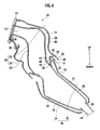
- FIG. 2 shows a heat shield structure of an exhaust manifold and a catalyst according to the embodiment of the present invention
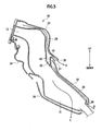
- FIG. 3 shows the heat shield structure of FIG. 2 with a heat shield member removed.
- UP indicates an upper side of a vehicle body (vehicle body upper side)
- DOWN indicates a floor side of the vehicle body (vehicle body floor side).
- a heat shield structure 10 of the exhaust manifold and catalyst is provided within a engine room 101 of a vehicle 100 or the like.
- a front end 13 of the exhaust manifold 12 is connected to a cylinder head of an engine 102, and the exhaust manifold 12 directs exhaust gas emitted from the engine 102 to an exhaust pipe 14.
- a catalyst 15 is provided between the exhaust manifold 12 and the exhaust pipe 14.
- the catalyst 15 renders the exhaust gas harmless and transmits the gas to the exhaust pipe 14.
- the catalyst 15 is connected to a rear end 16 of the exhaust manifold 12 and fixed with bolts 18 at a connecting portion 17.
- the exhaust manifold 12 and catalyst 15 connected to each other and the connecting portion 17 thereof are inclined downward (toward the vehicle body floor side) from the exhaust manifold 12 side to the exhaust pipe 14 side.
- the exhaust manifold 12 is bent in the vicinity of the engine toward the vehicle body floor side, and the rear end 16 of the exhaust manifold 12, catalyst 15, and exhaust pipe 14 are inclined toward the vehicle body floor side.
- the connecting portion 17 is provided to connect these inclined exhaust manifold 12 and catalyst 15.
- this bent flange 19 is provided in this connecting portion 17, a bent flange 19 is provided. As shown in FIG. 4, this bent flange 19 is provided with a bent wall 59, which is bent so as to have a substantially U-shaped cross-section and extended substantially horizontal to the aforementioned inclination.
- the bent flange 19 forms an open channel 40, and an open side of the channel 40 faces to the exhaust pipe 14 side (catalyst 15 side).
- This bent flange 19 is fastened by the bolts 18, which fix the catalyst 15 to the exhaust manifold 12, together with the catalyst 15 and fixed to the connecting portion 17. Since the bent flange 19 has a substantially U-shaped cross section, the rigidity thereof is enhanced.
- An exhaust manifold heat shield cover (exhaust manifold heat shield member) 20 includes an upper cover 22 covering an upper surface 21 of the exhaust manifold 12 and a lower cover 24 covering a lower surface 23 of the exhaust manifold 12.
- the upper and lower covers 22 and 24 are formed into shapes substantially along the upper and lower surfaces 21 and 23 of the exhaust manifold 12, respectively. As shown in FIG. 2, a side face 56 of the upper cover 22 is partially cut off to form a cut-off portion 57.
- upper and lower covers 22 and 24 are arranged opposite to each other so as to sandwich the exhaust manifold 12 above and below.
- the upper and lower covers 22 and 24 are fixed and attached to the exhaust manifold 12 by bolts 25.
- the upper cover 22 extends over the bent flange 19.
- a rear end 26 of the upper cover 22 is arranged on a vehicle body upper side of an end portion 41 of the bent flange 19 and is arranged on the exhaust pipe 14 side (catalyst 15 side) of the end portion 41.
- a rear aperture portion 28 is formed between the rear end 26 of the upper cover 22 and an outer surface 42 of the bent flange 19.
- a gap is provided along a path of the exhaust gas flow.
- the gap communicates with the rear aperture portion 28 to constitute a heat radiation path 29.
- a gap is provided by the cut-off portion 57 between the side face 56 of the upper cover 22 and a side face 62 of the lower cover 24.
- the gap forms a side aperture portion 58 on a side of the exhaust manifold heat shield cover 20.
- the side aperture portion 58 communicates with the heat radiation path 29.
- a catalyst heat shield cover (catalyst heat shield member) 30 includes an upper cover 32 covering an upper surface 31 of the catalyst 15 and a lower cover 34 covering a lower surface 33 of the catalyst 15.
- the upper and lower covers 32 and 34 are formed into shapes substantially along the upper and lower surfaces 31 and 33 of the catalyst 15, respectively.
- Side surfaces 52 and 53 of the upper and lower covers 32 and 34 are partially cut off to form cut-off portions 54 and 55, respectively.
- Flanges 47 and 48 are provided at side edges 45 and 46 of the upper and lower covers 32 and 34.
- the flanges 47 and 48 extend in a direction substantially perpendicular to the path of the exhaust gas flow. In the flanges 47 and 48, bolt holes 49 and 50, into which bolts 35 are inserted, are formed.
- upper and lower covers 32 and 34 are arranged opposite to each other so as to sandwich the catalyst 15 above and below.
- the upper and lower covers 32 and 34 are fixed to each other by the bolts 35 inserted through the bolt holes 49 and 50 of the flanges 47 and 48 abutting on each other, thus being attached to the catalyst 15.
- a front end 36 of the upper cover 32 is arranged in the channel 40 of the bent flange 19.
- the front end 36 of the upper cover 32 is arranged on a vehicle body floor side of the end portion 41 of the bent flange 19 and is arranged on the exhaust manifold 12 side of the end portion 41.
- a front aperture portion 37 is formed between the front end 36 of the upper cover 32 and an inner surface 43 of the bent flange 19.
- a gap is provided along the path of the exhaust gas flow and serves as a heat radiation path 39 in which the front aperture portion 37 communicates with a rear aperture portion 38.
- a gap provided by the cut-off portions 54 and 55 in a part between opposite side faces of the upper and lower covers 32 and 34 to form a side aperture portion 51.
- the side aperture portion 51 communicates with the heat radiation path 39.
- the rear end 26 of the upper cover 22 is arranged on the vehicle body upper side of the bent flange 19 while the front end 36 of the upper cover 32 is arranged in the channel 40 of the bent flange 19. Accordingly, the rear aperture portion 28 of the exhaust manifold heat shield cover 20 and the front aperture portion 37 of the catalyst heat shield cover 30 are separated by the outer and inner surfaces 42 and 43 of the bent flange 19, and the heat radiation paths 29 and 39 do not communicate with each other.
- heat generated from the exhaust manifold 12 passes through the heat radiation path 29 and is released from the side aperture portion 58 to the outside (see an arrow D).
- Heat from the catalyst 15 passes through the heat radiation path 39 and is released from the front aperture portion 37 to the outside (see an arrow E).
- the heat radiation paths 29 and 39 are disconnected from each other by the bent flange 19. Therefore, the heat from the catalyst 15 does not enter the heat radiation path 29 and is not mixed with the heat from the exhaust manifold 12.
- the rear end 26 of the upper cover 22 of the exhaust manifold heat shield cover 20 is arranged on the vehicle body upper side of the end portion 41 of the bent flange 19, and, moreover, the front end 36 of the upper cover 32 of the catalyst heat shield cover 30 is arranged on a vehicle body floor side of the end portion 41.
- the rear aperture portion 28 of the exhaust manifold heat shield cover 20 and the front aperture portion 37 of the catalyst heat shield cover 30 are separated by the outer and inner surfaces 42 and 43 of the bent flange 19, and the heat radiation paths 29 and 39 do not communicate with each other. Accordingly, heat from the exhaust manifold 12 and heat from the catalyst 15 are not mixed either when the vehicle is moving or stopped.
- heat from the exhaust manifold 12 is released to the outside from the rear aperture portion 28 or the side aperture portion 58
- heat from the catalyst 15 is released to the outside from the rear aperture portion 38, the side aperture portion 51, or the front aperture portion 37.
- heat from the exhaust manifold 12 and heat from the catalyst 15 can be efficiently released without being mixed with each other.
- the rear end 26 of the upper cover 22 of the exhaust manifold heat shield cover 20 is arranged on the exhaust pipe 14 side of the end portion 41 of the bent flange 19, and the front end 36 of the upper cover 32 of the catalyst heat shield cover 30 is arranged on the exhaust manifold 12 side of the end portion 41.
- the upper cover 22 and the upper cover 32 horizontally overlap each other with the bent wall 59 interposed therebetween.
- this liquid does not enter the heat radiation path 29 or 39 through the rear aperture portion 28 or front aperture portion 37 and not reach the exhaust manifold 12 or catalyst 15.
- the side surfaces 52 and 53 of the upper and lower covers 32 and 34 are partially cut off to provide the side aperture portion 51 communicating with the heat radiation path 39. Accordingly, while the vehicle is moving, heat from the catalyst 15 passes through the heat radiation path 39 and is released not only from the rear aperture portion 38 but also from the side aperture portion 51. Therefore, heat can be efficiently released even though the catalyst 15 is covered with the catalyst heat shield cover 30 above and below. In the case of using a work tool to connect the exhaust manifold 12 and catalyst 15 or to change the catalyst 15 or exhaust pipe 14, space for such a work can be secured by the side aperture portion 51. The work is not obstructed by the catalyst heat shield cover 30 and can be easily carried out.
- the present invention is not limited to the aforementioned embodiment.
- the rear end 26 of the upper cover 22 of the exhaust manifold heat shield cover 20 is arranged on the vehicle body upper side of the end portion 41 of the bent flange 19 and on the exhaust pipe 14 side of the end portion 41, and the front end 36 of the upper cover 32 of the catalyst heat shield cover 30 is arranged on a vehicle body upper side of the end portion 41 and on the exhaust manifold 12 side of the end portion 41.
- the rear end 26 needs to be arranged on a vehicle body upper side of the end portion 41 while the front end 36 needs to be arranged on a vehicle body upper side of the end portion 41.
- the rear end 26 is arranged on the exhaust pipe 14 side of the end portion 41, and the front end 36 is arranged on the exhaust manifold 12 side of the end portion 41.
Landscapes
- Engineering & Computer Science (AREA)
- Chemical & Material Sciences (AREA)
- Combustion & Propulsion (AREA)
- Mechanical Engineering (AREA)
- General Engineering & Computer Science (AREA)
- Chemical Kinetics & Catalysis (AREA)
- Health & Medical Sciences (AREA)
- Toxicology (AREA)
- Exhaust Gas After Treatment (AREA)
- Exhaust Silencers (AREA)
- Cooling, Air Intake And Gas Exhaust, And Fuel Tank Arrangements In Propulsion Units (AREA)
Applications Claiming Priority (2)
| Application Number | Priority Date | Filing Date | Title |
|---|---|---|---|
| JP2004058557A JP4375061B2 (ja) | 2004-03-03 | 2004-03-03 | エキゾーストマニホールド及びキャタリストの遮熱構造 |
| JP2004058557 | 2004-03-03 |
Publications (2)
| Publication Number | Publication Date |
|---|---|
| EP1577516A1 true EP1577516A1 (de) | 2005-09-21 |
| EP1577516B1 EP1577516B1 (de) | 2006-08-09 |
Family
ID=34836472
Family Applications (1)
| Application Number | Title | Priority Date | Filing Date |
|---|---|---|---|
| EP05250987A Expired - Lifetime EP1577516B1 (de) | 2004-03-03 | 2005-02-22 | Wärmeschild für Abgaskrümmer und Katalysator |
Country Status (5)
| Country | Link |
|---|---|
| US (1) | US7162868B2 (de) |
| EP (1) | EP1577516B1 (de) |
| JP (1) | JP4375061B2 (de) |
| CN (1) | CN100339572C (de) |
| DE (1) | DE602005000062T2 (de) |
Cited By (5)
| Publication number | Priority date | Publication date | Assignee | Title |
|---|---|---|---|---|
| FR2919532A1 (fr) * | 2007-07-31 | 2009-02-06 | Renault Sas | Systeme de protection de pieces chaudes d'un moteur |
| EP2522822A1 (de) | 2011-05-09 | 2012-11-14 | Peugeot Citroën Automobiles Sa | System, das einen Verbrennungsmotor umfasst, U-Einheit zur Aufbereitung von Abgas und optimisierter Wärmebildschirm |
| EP3064732A1 (de) * | 2015-03-03 | 2016-09-07 | Toyota Jidosha Kabushiki Kaisha | Wärmeisolierung |
| FR3042155A1 (fr) * | 2015-10-12 | 2017-04-14 | Renault Sas | Ecran de protection de ligne d'echappement |
| EP3670305A4 (de) * | 2017-09-28 | 2020-07-29 | Mazda Motor Corporation | Unterbodenstruktur eines fahrzeuges |
Families Citing this family (21)
| Publication number | Priority date | Publication date | Assignee | Title |
|---|---|---|---|---|
| JP2006070705A (ja) * | 2004-08-31 | 2006-03-16 | Honda Motor Co Ltd | 車両用エンジンの排気装置 |
| DE102005006577A1 (de) * | 2005-02-11 | 2006-08-24 | Elringklinger Ag | Strukturbauteil, insbesondere Abschirmteil |
| DE102005006320A1 (de) * | 2005-02-11 | 2006-08-24 | Elringklinger Ag | Abschirmteil, insbesondere Hitzeschild |
| US7874149B2 (en) * | 2005-08-17 | 2011-01-25 | Kawasaki Jukogyo Kabushiki Kaisha | Exhaust apparatus for vehicle, and motorcycle having the same |
| DE102006003229A1 (de) * | 2006-01-24 | 2007-08-02 | Federal-Mogul Sealing Systems Gmbh | Hitzeschild |
| JP2008069729A (ja) * | 2006-09-15 | 2008-03-27 | Toyota Motor Corp | マフラ |
| US7849681B2 (en) * | 2007-01-02 | 2010-12-14 | Cummins, Inc. | Apparatus, system, and method for engine-generated heat utilization in a NOx-adsorber aftertreatment system |
| DE102007007638A1 (de) * | 2007-02-16 | 2008-08-21 | Daimler Ag | Brennkraftmaschine mit mehreren Brennräumen |
| DE102007057309A1 (de) * | 2007-11-28 | 2009-06-10 | Continental Automotive Gmbh | Hitzeschild und Turbolader mit einem Hitzeschild |
| CA2709665C (en) * | 2007-12-21 | 2013-03-12 | Seok-Ju Song | Fuel heating equipment of diesel engine |
| JP5202140B2 (ja) * | 2008-07-04 | 2013-06-05 | ダイハツ工業株式会社 | 排気系の遮熱冷却装置 |
| DE102010005823A1 (de) * | 2010-01-27 | 2011-07-28 | GM Global Technology Operations LLC, ( n. d. Ges. d. Staates Delaware ), Mich. | System für eine Abgasanlage eines Kraftfahrzeuges sowie entsprechende Abgasanlage |
| DE102010062049A1 (de) * | 2010-11-26 | 2012-05-31 | J. Eberspächer GmbH & Co. KG | Schalldämpfer |
| JP5773975B2 (ja) * | 2012-12-26 | 2015-09-02 | 本田技研工業株式会社 | 鞍乗り型車両の排気管カバー構造 |
| JP6300835B2 (ja) | 2013-02-22 | 2018-03-28 | インターフェイス パフォーマンス マテリアルズ, インコーポレイテッド | 軽量熱シールド |
| JP5843830B2 (ja) * | 2013-09-18 | 2016-01-13 | アイシン高丘株式会社 | 触媒ケース一体型排気マニホルド |
| JP6179488B2 (ja) * | 2014-08-29 | 2017-08-16 | トヨタ自動車株式会社 | 内燃機関及びシリンダヘッド |
| CN107109998A (zh) * | 2014-12-25 | 2017-08-29 | 本田技研工业株式会社 | 内燃机的废气净化装置 |
| DE102015113137B4 (de) * | 2015-08-10 | 2021-01-14 | Tenneco Gmbh | Abgasgehäuse |
| JP6418263B2 (ja) * | 2017-03-10 | 2018-11-07 | マツダ株式会社 | エンジンの排気装置 |
| US12584434B2 (en) * | 2023-01-12 | 2026-03-24 | Brp-Rotax Gmbh & Co. Kg | Protective heat shield enclosure for turbocharged engines |
Citations (5)
| Publication number | Priority date | Publication date | Assignee | Title |
|---|---|---|---|---|
| JP2002161739A (ja) * | 2000-11-24 | 2002-06-07 | Suzuki Motor Corp | 触媒コンバータ |
| US20020184880A1 (en) * | 2001-06-12 | 2002-12-12 | Dana Corporation | Insulated heat shield |
| US6555070B1 (en) * | 1998-10-05 | 2003-04-29 | Scambia Industrial Developments Ag | Exhaust component and method for producing an exhaust component |
| US20030080519A1 (en) * | 2001-10-31 | 2003-05-01 | Kerchner Douglas M. | Gasket and heat shield for a flanged joint |
| US6681890B1 (en) * | 2001-11-30 | 2004-01-27 | Dana Corporation | Sound barrier layer for insulated heat shield |
Family Cites Families (10)
| Publication number | Priority date | Publication date | Assignee | Title |
|---|---|---|---|---|
| US5768890A (en) * | 1993-11-12 | 1998-06-23 | Benteler Automotive Corporation | Exhaust air rail manifold |
| JP3649306B2 (ja) * | 1996-09-12 | 2005-05-18 | 本田技研工業株式会社 | 多気筒内燃機関の排気マニホルド |
| JPH10331632A (ja) * | 1997-05-30 | 1998-12-15 | Suzuki Motor Corp | 内燃機関の排気マニホルド装置 |
| JPH11107772A (ja) | 1997-10-03 | 1999-04-20 | Nippon Reinz Co Ltd | ヒートインシュレータ |
| JP3452796B2 (ja) * | 1998-05-21 | 2003-09-29 | ダイハツ工業株式会社 | スラント型内燃機関における排気マニホールドのカバー装置 |
| US6230490B1 (en) * | 1998-11-09 | 2001-05-15 | Suzuki Motor Corp. | Exhaust manifold for internal combustion engines |
| JP4014355B2 (ja) * | 2000-07-03 | 2007-11-28 | 本田技研工業株式会社 | 排気ガス還流装置 |
| JP2002089248A (ja) * | 2000-09-08 | 2002-03-27 | Calsonic Kansei Corp | 自動車用排気システム |
| JP2002276356A (ja) * | 2001-03-19 | 2002-09-25 | Mazda Motor Corp | 車載用エンジンの排気構造 |
| US6647715B2 (en) * | 2001-11-30 | 2003-11-18 | Van-Rob Stampings Inc. | Heat shield for an exhaust system of an internal combustion engine |
-
2004
- 2004-03-03 JP JP2004058557A patent/JP4375061B2/ja not_active Expired - Lifetime
-
2005
- 2005-02-22 US US11/061,613 patent/US7162868B2/en not_active Expired - Lifetime
- 2005-02-22 EP EP05250987A patent/EP1577516B1/de not_active Expired - Lifetime
- 2005-02-22 DE DE602005000062T patent/DE602005000062T2/de not_active Expired - Lifetime
- 2005-03-03 CN CNB2005100518806A patent/CN100339572C/zh not_active Expired - Lifetime
Patent Citations (5)
| Publication number | Priority date | Publication date | Assignee | Title |
|---|---|---|---|---|
| US6555070B1 (en) * | 1998-10-05 | 2003-04-29 | Scambia Industrial Developments Ag | Exhaust component and method for producing an exhaust component |
| JP2002161739A (ja) * | 2000-11-24 | 2002-06-07 | Suzuki Motor Corp | 触媒コンバータ |
| US20020184880A1 (en) * | 2001-06-12 | 2002-12-12 | Dana Corporation | Insulated heat shield |
| US20030080519A1 (en) * | 2001-10-31 | 2003-05-01 | Kerchner Douglas M. | Gasket and heat shield for a flanged joint |
| US6681890B1 (en) * | 2001-11-30 | 2004-01-27 | Dana Corporation | Sound barrier layer for insulated heat shield |
Non-Patent Citations (1)
| Title |
|---|
| PATENT ABSTRACTS OF JAPAN vol. 2002, no. 10 10 October 2002 (2002-10-10) * |
Cited By (5)
| Publication number | Priority date | Publication date | Assignee | Title |
|---|---|---|---|---|
| FR2919532A1 (fr) * | 2007-07-31 | 2009-02-06 | Renault Sas | Systeme de protection de pieces chaudes d'un moteur |
| EP2522822A1 (de) | 2011-05-09 | 2012-11-14 | Peugeot Citroën Automobiles Sa | System, das einen Verbrennungsmotor umfasst, U-Einheit zur Aufbereitung von Abgas und optimisierter Wärmebildschirm |
| EP3064732A1 (de) * | 2015-03-03 | 2016-09-07 | Toyota Jidosha Kabushiki Kaisha | Wärmeisolierung |
| FR3042155A1 (fr) * | 2015-10-12 | 2017-04-14 | Renault Sas | Ecran de protection de ligne d'echappement |
| EP3670305A4 (de) * | 2017-09-28 | 2020-07-29 | Mazda Motor Corporation | Unterbodenstruktur eines fahrzeuges |
Also Published As
| Publication number | Publication date |
|---|---|
| DE602005000062D1 (de) | 2006-09-21 |
| JP4375061B2 (ja) | 2009-12-02 |
| US7162868B2 (en) | 2007-01-16 |
| JP2005248778A (ja) | 2005-09-15 |
| CN1664323A (zh) | 2005-09-07 |
| EP1577516B1 (de) | 2006-08-09 |
| CN100339572C (zh) | 2007-09-26 |
| US20050193726A1 (en) | 2005-09-08 |
| DE602005000062T2 (de) | 2007-03-08 |
Similar Documents
| Publication | Publication Date | Title |
|---|---|---|
| US7162868B2 (en) | Heat shield structure of exhaust manifold and catalyst | |
| EP2211036B1 (de) | Motorrad mit einer Abgasreinigungsvorrichtung mit verbessertem Design | |
| US7137722B2 (en) | Motorcycle front body structure | |
| US20110180345A1 (en) | Cowling structure for saddle-ride type vehicle | |
| JP2013068123A (ja) | 小型車両のプロテクター付きマフラー装置 | |
| US8783024B2 (en) | Exhaust chamber in motorcycle exhaust system | |
| US7174991B1 (en) | Muffler for internal combustion engine | |
| US20070227812A1 (en) | Muffler | |
| JP2017061255A (ja) | 車両の後部構造 | |
| JP2014181678A (ja) | 鞍乗型車両の内燃機関 | |
| CA1297414C (en) | Silencer | |
| EP1186755A2 (de) | Abgasschalldämpfer | |
| JP2007015481A (ja) | 車両の排水構造 | |
| JP2009029183A (ja) | エンジンの冷却構造 | |
| JP5710333B2 (ja) | フード | |
| JP4569435B2 (ja) | 車両吸気ダクトの吸気取入構造 | |
| JP2001193450A (ja) | エンジンの排気系支持構造 | |
| US7900442B2 (en) | Engine including secondary air supply apparatus | |
| JP4357910B2 (ja) | 自動二輪車のマフラーの接続構造とカバー | |
| JP6668777B2 (ja) | 車両の遮熱構造 | |
| JP2007085301A (ja) | 多気筒エンジン | |
| US10350987B2 (en) | Upper structure of vehicle engine | |
| US8584449B2 (en) | Manifold for a multicylinder internal combustion engine | |
| JP2005171792A (ja) | 自動車の排気系の遮熱板 | |
| EP2211035B1 (de) | Motorrad mit einer Abgasreinigungsvorrichtung mit verbessertem Design |
Legal Events
| Date | Code | Title | Description |
|---|---|---|---|
| PUAI | Public reference made under article 153(3) epc to a published international application that has entered the european phase |
Free format text: ORIGINAL CODE: 0009012 |
|
| 17P | Request for examination filed |
Effective date: 20050303 |
|
| AK | Designated contracting states |
Kind code of ref document: A1 Designated state(s): AT BE BG CH CY CZ DE DK EE ES FI FR GB GR HU IE IS IT LI LT LU MC NL PL PT RO SE SI SK TR |
|
| AX | Request for extension of the european patent |
Extension state: AL BA HR LV MK YU |
|
| GRAP | Despatch of communication of intention to grant a patent |
Free format text: ORIGINAL CODE: EPIDOSNIGR1 |
|
| GRAS | Grant fee paid |
Free format text: ORIGINAL CODE: EPIDOSNIGR3 |
|
| AKX | Designation fees paid |
Designated state(s): DE FR GB |
|
| GRAA | (expected) grant |
Free format text: ORIGINAL CODE: 0009210 |
|
| AK | Designated contracting states |
Kind code of ref document: B1 Designated state(s): DE FR GB |
|
| REG | Reference to a national code |
Ref country code: GB Ref legal event code: FG4D |
|
| REF | Corresponds to: |
Ref document number: 602005000062 Country of ref document: DE Date of ref document: 20060921 Kind code of ref document: P |
|
| ET | Fr: translation filed | ||
| PLBE | No opposition filed within time limit |
Free format text: ORIGINAL CODE: 0009261 |
|
| STAA | Information on the status of an ep patent application or granted ep patent |
Free format text: STATUS: NO OPPOSITION FILED WITHIN TIME LIMIT |
|
| 26N | No opposition filed |
Effective date: 20070510 |
|
| REG | Reference to a national code |
Ref country code: FR Ref legal event code: PLFP Year of fee payment: 12 |
|
| REG | Reference to a national code |
Ref country code: FR Ref legal event code: PLFP Year of fee payment: 13 |
|
| REG | Reference to a national code |
Ref country code: FR Ref legal event code: PLFP Year of fee payment: 14 |
|
| REG | Reference to a national code |
Ref country code: DE Ref legal event code: R084 Ref document number: 602005000062 Country of ref document: DE |
|
| REG | Reference to a national code |
Ref country code: GB Ref legal event code: 746 Effective date: 20230929 |
|
| PGFP | Annual fee paid to national office [announced via postgrant information from national office to epo] |
Ref country code: DE Payment date: 20240123 Year of fee payment: 20 Ref country code: GB Payment date: 20240123 Year of fee payment: 20 |
|
| PGFP | Annual fee paid to national office [announced via postgrant information from national office to epo] |
Ref country code: FR Payment date: 20240123 Year of fee payment: 20 |
|
| REG | Reference to a national code |
Ref country code: DE Ref legal event code: R071 Ref document number: 602005000062 Country of ref document: DE |
|
| REG | Reference to a national code |
Ref country code: GB Ref legal event code: PE20 Expiry date: 20250221 |
|
| PG25 | Lapsed in a contracting state [announced via postgrant information from national office to epo] |
Ref country code: GB Free format text: LAPSE BECAUSE OF EXPIRATION OF PROTECTION Effective date: 20250221 |