EP1577586A1 - Dispositif pour le force limitative d'un différentiel - Google Patents
Dispositif pour le force limitative d'un différentiel Download PDFInfo
- Publication number
- EP1577586A1 EP1577586A1 EP04029664A EP04029664A EP1577586A1 EP 1577586 A1 EP1577586 A1 EP 1577586A1 EP 04029664 A EP04029664 A EP 04029664A EP 04029664 A EP04029664 A EP 04029664A EP 1577586 A1 EP1577586 A1 EP 1577586A1
- Authority
- EP
- European Patent Office
- Prior art keywords
- inner shaft
- housing
- clutch
- gear
- cam
- Prior art date
- Legal status (The legal status is an assumption and is not a legal conclusion. Google has not performed a legal analysis and makes no representation as to the accuracy of the status listed.)
- Granted
Links
- 230000007246 mechanism Effects 0.000 claims abstract description 50
- 230000033001 locomotion Effects 0.000 claims abstract description 23
- 230000000694 effects Effects 0.000 claims description 2
- 230000005540 biological transmission Effects 0.000 abstract description 23
- 230000009471 action Effects 0.000 abstract description 2
- 238000010276 construction Methods 0.000 abstract description 2
- 230000001133 acceleration Effects 0.000 description 7
- 230000035939 shock Effects 0.000 description 4
- 230000004907 flux Effects 0.000 description 3
- 238000003754 machining Methods 0.000 description 3
- 239000002184 metal Substances 0.000 description 3
- 229910052751 metal Inorganic materials 0.000 description 3
- XEEYBQQBJWHFJM-UHFFFAOYSA-N Iron Chemical compound [Fe] XEEYBQQBJWHFJM-UHFFFAOYSA-N 0.000 description 2
- 230000008859 change Effects 0.000 description 2
- 241000490025 Schefflera digitata Species 0.000 description 1
- 239000006185 dispersion Substances 0.000 description 1
- 238000009826 distribution Methods 0.000 description 1
- 229910052742 iron Inorganic materials 0.000 description 1
- 235000015250 liver sausages Nutrition 0.000 description 1
- 238000005461 lubrication Methods 0.000 description 1
- 238000004519 manufacturing process Methods 0.000 description 1
- 230000004048 modification Effects 0.000 description 1
- 238000012986 modification Methods 0.000 description 1
- 238000000926 separation method Methods 0.000 description 1
- 230000007704 transition Effects 0.000 description 1
- 238000003466 welding Methods 0.000 description 1
Images
Classifications
-
- F—MECHANICAL ENGINEERING; LIGHTING; HEATING; WEAPONS; BLASTING
- F16—ENGINEERING ELEMENTS AND UNITS; GENERAL MEASURES FOR PRODUCING AND MAINTAINING EFFECTIVE FUNCTIONING OF MACHINES OR INSTALLATIONS; THERMAL INSULATION IN GENERAL
- F16H—GEARING
- F16H48/00—Differential gearings
- F16H48/06—Differential gearings with gears having orbital motion
- F16H48/10—Differential gearings with gears having orbital motion with orbital spur gears
-
- F—MECHANICAL ENGINEERING; LIGHTING; HEATING; WEAPONS; BLASTING
- F16—ENGINEERING ELEMENTS AND UNITS; GENERAL MEASURES FOR PRODUCING AND MAINTAINING EFFECTIVE FUNCTIONING OF MACHINES OR INSTALLATIONS; THERMAL INSULATION IN GENERAL
- F16H—GEARING
- F16H48/00—Differential gearings
- F16H48/20—Arrangements for suppressing or influencing the differential action, e.g. locking devices
- F16H48/22—Arrangements for suppressing or influencing the differential action, e.g. locking devices using friction clutches or brakes
-
- F—MECHANICAL ENGINEERING; LIGHTING; HEATING; WEAPONS; BLASTING
- F16—ENGINEERING ELEMENTS AND UNITS; GENERAL MEASURES FOR PRODUCING AND MAINTAINING EFFECTIVE FUNCTIONING OF MACHINES OR INSTALLATIONS; THERMAL INSULATION IN GENERAL
- F16H—GEARING
- F16H48/00—Differential gearings
- F16H48/20—Arrangements for suppressing or influencing the differential action, e.g. locking devices
- F16H48/30—Arrangements for suppressing or influencing the differential action, e.g. locking devices using externally-actuatable means
- F16H48/34—Arrangements for suppressing or influencing the differential action, e.g. locking devices using externally-actuatable means using electromagnetic or electric actuators
-
- F—MECHANICAL ENGINEERING; LIGHTING; HEATING; WEAPONS; BLASTING
- F16—ENGINEERING ELEMENTS AND UNITS; GENERAL MEASURES FOR PRODUCING AND MAINTAINING EFFECTIVE FUNCTIONING OF MACHINES OR INSTALLATIONS; THERMAL INSULATION IN GENERAL
- F16H—GEARING
- F16H48/00—Differential gearings
- F16H48/20—Arrangements for suppressing or influencing the differential action, e.g. locking devices
- F16H2048/204—Control of arrangements for suppressing differential actions
-
- F—MECHANICAL ENGINEERING; LIGHTING; HEATING; WEAPONS; BLASTING
- F16—ENGINEERING ELEMENTS AND UNITS; GENERAL MEASURES FOR PRODUCING AND MAINTAINING EFFECTIVE FUNCTIONING OF MACHINES OR INSTALLATIONS; THERMAL INSULATION IN GENERAL
- F16H—GEARING
- F16H48/00—Differential gearings
- F16H48/20—Arrangements for suppressing or influencing the differential action, e.g. locking devices
- F16H48/30—Arrangements for suppressing or influencing the differential action, e.g. locking devices using externally-actuatable means
- F16H48/34—Arrangements for suppressing or influencing the differential action, e.g. locking devices using externally-actuatable means using electromagnetic or electric actuators
- F16H2048/346—Arrangements for suppressing or influencing the differential action, e.g. locking devices using externally-actuatable means using electromagnetic or electric actuators using a linear motor
Definitions
- the present invention relates to a differential limiting device of the type that the transmission torque of a pilot clutch is amplified by a cam mechanism to bring a main clutch into friction engagement.
- differential limiting devices for vehicles there has been known one which is constructed by combining a planetary gear mechanism and an electromagnetic pilot clutch mechanism, as described in Japanese unexamined, published patent application No. 9-144845 (144845/1997).
- the differential limiting device described in the patent document is provided with the planetary gear mechanism which is composed of planetary gears in meshing with a sun gear and a ring gear and a housing rotatably receiving the planetary gears in receiving bores thereof.
- the differential limiting device is further provided with a main clutch arranged between the ring gear and the sun gear.
- connection means i.e., the pilot clutch mechanism
- the transmission torque from an engine is transmitted to the housing, and the transmission torque transmitted to the housing is distributed by the planetary gear mechanism to the sun gear and the ring gear. Further, the main clutch is brought into friction engagement by the operation of the electromagnetic pilot clutch mechanism to limit the differential rotation between the ring gear and the sun gear.
- the differential limiting device of the aforementioned type is mounted on a drive power transmission system of a vehicle and is used to constitute the vehicle as a four-wheel drive vehicle.
- the differential limiting device under this circumstance, it is sometimes the case that reversal occurs in the differential rotation while torque transmission is being performed with the cam mechanism being operated by the pilot clutch.
- the occurrence of the reversal in the differential rotation causes the differential limiting device or devices around the same to generate a strange noise.
- the reversal takes place between the rotational speed of the housing to which the rotation from the engine is transmitted and the rotational speed of the sun gear to which the rotation of the front wheels is transmitted, or the rotational speed of the ring gear to which the rotation of the rear wheels is transmitted. That is, the reversal takes place when the vehicle transitions from the acceleration state to the deceleration state or from the deceleration state to the acceleration state.
- the cam rotational angle of the cam mechanism, frictions among the component members and the like may occasionally cooperate to generate the strange noise.
- the cause may be analyzed as follows. That is, when a reversal occurs in the cam mechanism, the pressuring force exerted on the main clutch is lost, and the main clutch thus comes not to generate the friction torque. When the differential rotation further proceeds, the main clutch again receives the pressuring force from the cam mechanism and revives to generate a predetermined torque. Where the time continues long during which the main clutch does not generate any friction torque, the rotational speed difference becomes large between the idle rotations of main outer clutch plates and main inner clutch plates, and a large difference in rotational energy is produced therebetween. When the main clutch is restored to the state in which it again transmits the torque, the large difference in energy is absorbed within a very short period of time, which causes the strange noise to be generated at the cam mechanism.
- the present invention is made to solve the foregoing various problems, and it is a primary object of the present invention to provide an improved differential limiting device for a vehicle capable of suppressing the generations of the strange noise and shock which are caused by the reversal in motion transmission of the cam mechanism.
- a differential limiting device for a vehicle comprising a housing rotatable about a rotational axis; first and second inner shafts arranged in the housing in tandem on the rotational axis and each rotatable relative to the housing; a ring gear provided in the housing to be rotatable bodily with the first inner shaft; a sun gear provided on the second inner shaft in the housing to be rotatable bodily with the second inner shaft; a planetary carrier rotatable bodily with the housing in the housing and provided with a support portion; and at least one planetary gear rotatably carried by the support portion of the planetary carrier in meshing engagement with the sun gear and the ring gear.
- the differential limiting device further comprises a cam ring provided in tandem with the second inner shaft in axial alignment and rotatable relative to the second inner shaft; a pilot clutch for transmitting drive power between the housing and the cam ring when in friction engagement, to selectively effect relative rotation between the cam ring and the second inner shaft; and pilot clutch control means for controlling the friction engagement of the pilot clutch.
- a cam mechanism is further provided including cam grooves formed on mutually facing end surfaces of the cam ring and the second inner shaft and cam followers held in the cam grooves for axially moving the second inner shaft upon relative rotation between the cam ring and the second inner shaft.
- a main clutch is also provided for transmitting drive power between the housing rotatable bodily with the planetary carrier and the first inner shaft rotatable bodily with the ring gear, with outer and inner clutch plates thereof being spline-engaged respectively with the housing and the first inner shaft.
- the main clutch limits the relative rotation between the planetary carrier and the ring gear when brought into friction engagement by the axial movement of the second inner shaft.
- the inventor of the present invention took two states into consideration. That is, one is the state wherein the first inner shaft is idling, with the pilot clutch kept in friction engagement by the pilot clutch control means and hence, with the main clutch kept in friction engagement. The other is the state wherein the second inner shaft is idling, with the pilot clutch kept in friction engagement by the pilot clutch control means and hence, with the main clutch kept in friction engagement. Then, the inventor studied about the differential rotational speeds between any two members of the planetary carrier, the sun gear and the ring gear. As a result, the rotational speed differences were found as specified in the following Table 1.
- N represents a reference rotational speed
- Z1 represents the number of the ring gear teeth
- Z2 represents the number of the sun gear teeth wherein a relation of Z1 > Z2 holds.
- the relative rotation between the planetary carrier and the ring gear is the lowest of the three inter-element relative rotations.
- the reversal in motion transmission of the cam mechanism can be completed earlier than the reversal in motion transmission of the main clutch throughout backlashes at the spline engagement portions thereof.
- the cam mechanism completes the reversal in motion transmission while the second inner shaft is being permitted to rotate relative to the housing. In other words, during the reversal motion of the cam mechanism, the second inner shaft is being released from the tight drive connection with any of the housing and the first inner shaft.
- the second inner shaft which is being released from the tight drive connection with any of the housing and the first inner shaft can easily yield to and follow the rotation of the cam ring. Accordingly, a shock which is generated when the drive connection between the cam ring and the second inner shaft is revived upon the completion of the reversal motion can be suppressed to be small, so that the generation of the strange noise can also be suppressed. This advantageously makes it unnecessary to precisely control the dimensions of the backlashes provided in the main clutch and the cam mechanism in the machining processes therefor.
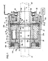
- the differential limiting device 10 is used for example to distribute the drive power of an engine (labeled) to front and rear wheels (not shown) in a four-wheel drive vehicle.
- a numeral 11 denotes a front housing taking a bottomed cylindrical shape, and the front housing 11 is carried in a clutch case (not shown) to be rotatable about an rotational axis O.
- the front housing 11 is drivingly connected to an input shaft (not numbered) to which the drive torque from the engine is transmitted, so that the front housing 11 is rotated upon receipt of the drive torque from the engine.
- a rear housing 12 is screw-secured to an open end portion of the front housing 11.
- a first inner shaft 13 and a second inner shaft 14 are arranged in tandem to be rotatable relative to each other on the rotational axis O and define therearound a receiving chamber 15 which is fluid-tightly filled with lubrication oil.
- the first and second inner shafts 13, 14 are respectively connected to two output shafts 41 and 42 for transmitting the drive power respectively to the front wheels and rear wheels.
- a main clutch 16 is received at one axial end, and a pilot clutch 17 is received at the other axial end.
- a planetary gear mechanism 18 is arranged between the main clutch 16 and the pilot clutch 17.
- the main clutch 16 is constituted by having plural main outer clutch plates 16a and plural main inner clutch plates 16b arranged in an alternate fashion.
- the main outer clutch plates 16a are made of iron and are spline-engaged with spline grooves 11a formed on the internal surface of the front housing 11, so that they are prevented from relative rotation to the front housing 11, but are movable relative thereto in the axial direction parallel to the rotational axis O.
- the main inner clutch plates 16b are each constituted by pasting paper-made friction members on both end surfaces of an iron-made core plate.
- the main inner clutch plates 16b are spline-engaged with spline grooves 13a formed on the external surface of the first inner shaft 13, so that they are prevented from relative rotation to the first inner shaft 13, but are movable relative thereto in the axial direction parallel to the rotational axis O.
- the main outer clutch plates 16a and the main inner clutch plates 16b are contacted and frictionally engaged with each other when in engagement, but are separated and disengaged from each other when in separation.
- the first and second inner shafts 13, 14 are supported to be axially movable through a slight distance.
- the first inner shaft 13 is provided with a shoulder portion 13s, and a pressuring plate 13b is interposed between the shoulder portion 13s and an endmost one of the main inner clutch plates 16b.
- the main clutch 16 is arranged between a bottom end surface of the front housing 11 and the shoulder portion 13s of the first inner shaft 13 in the axial direction and is pressured by the shoulder portion 13s upon the bottom end surface of the front housing 11 when the first inner shaft 13 is axially moved through the slight distance by being pushed by the second inner shaft 14, as described later in detail.
- the pilot clutch 17 is composed of plural pilot outer clutch plates 17a and plural pilot inner clutch plates 17b.
- the pilot outer clutch plates 17a are spline-engaged with the spline grooves 11a of the front housing 11, so that they are prevented from relative rotation to the front housing 11, but are movable relative thereto in the axial direction parallel to the rotational axis O.
- the pilot inner clutch plates 17b are arranged in an alternate fashion with the pilot outer clutch plates 17a and are spline-engaged with the external surface of a cam ring 19 arranged between the second inner shaft 14 and the rear housing 12, so that they are prevented from relative rotation to the cam ring 19, but are movable relative thereto in the axial direction parallel to the rotational axis O.
- the cam ring 19 is rotatably carried at its one end surface on the rear housing 12 through a needle bearing 20.
- Plural cam grooves 19a constituting a cam mechanism 21 are formed on the other end surface of the cam ring 19 at a regular interval in the circumferential direction thereof.
- cam grooves 14a On an end surface facing the cam ring 19 of the second inner shaft 14, there are formed plural cam grooves 14a at a regular interval in the circumferential direction thereof. These cam grooves 14a and the cam grooves 19a formed on the cam ring 19 define plural cam spaces, which respectively retain ball-like cam followers 22 therein.
- the cam mechanism 21 is composed of the second inner shaft 14, the cam ring 19 and the cam followers 22.
- the backlash in the cam mechanism 21 is set to be equal to or greater than the backlash that the main outer clutch plates 16a define at the spline engagement portions with the spline grooves 11 a and than the backlash that the main inner clutch plates 16b define at the spline engagement portions with the spline grooves 13a.
- An annular armature 23 is arranged between the pilot clutch 17 and the planetary gear mechanism 18.
- the armature 23 is spline-engaged at its external surface with the spline grooves 11a formed on the internal surface of the front housing 11, so that it is prevented from relative rotation to the front housing 11, but is movable relative thereto in the axial direction parallel to the rotational axis O.
- an electromagnet 24 which serves as pilot clutch control means.
- the rear housing 12 is secured to the open end portion of the front housing 11 at a portion (right side as viewed in Figure 1) behind the pilot outer clutch plates 17a.
- the rear housing 12 is composed of a large-diameter rear housing portion12a made of a magnetic metal, a small-diameter rear housing portion 12b made of a magnetic metal, and an intermediate member 12c made of a non-magnetic metal.
- the large-diameter rear housing portion12a takes a cylindrical shape and is screw-fixed to the internal surface of the open end portion of the front housing 11.
- the small-diameter rear housing portion 12b is of a stepped cylindrical shape formed with an internal bore 12d, through which the output shaft 42 spline-engaged with the second inner shaft 14 passes for transmission of drive power to the rear wheels.
- the intermediate member 12c of an annular shape is interposed between the internal surface of the large-diameter rear housing portion12a and the outer surface of the small-diameter rear housing portion 12b and is secured by welding or the like to the large-diameter rear housing portion12a and the small-diameter rear housing portion 12b.
- the electromagnet 24 takes an annular shape and has electric current applied thereto through a terminal (not numbered).
- the electromagnet 24 is secured to a yoke 25 at a position surrounded by the large and small- diameter rear housing portions 12a, 12b and the intermediate member 12c.
- the yoke 25 is rotatably carried on the small-diameter rear housing portion 12b through a bearing 26 with a small clearance being held relative to the large and small- diameter rear housing portions 12a, 12b.
- the planetary gear mechanism 18 is primarily composed of a planetary carrier 27, a ring gear 28, several (usually, three) planetary gears 29, and a sun gear 30 which is formed on the second inner shaft 14.
- the planetary carrier 27 is arranged between the front housing 11 and the second inner shaft 14.
- the planetary carrier 27 is spline-engaged with the spline grooves 11 a of the front housing 11 at the external surface thereof and is mounted with a play on the second inner shaft 14 at the internal surface thereof.
- the planetary carrier 27 is provided with an annular support portion 27a, in which plural receiving bore 27b each extending in parallel to the rotational axis O are formed at a regular interval in the circumferential direction.
- the receiving bore 27b are opened at the internal surface side and the external surface side of the annular support portion 27a and respectively receives the planetary gears 29 to be rotatable therein. Respective one ends (right ends as viewed in Figure 1) of the planetary gears 29 are kept in contact with bottom end surfaces of the receiving bore 27b, while respective other ends (left ends as viewed in Figure 1) of the planetary gears 29 are kept in contact with an inner end surface of the ring gear 28 through a thrust washer 31.
- the planetary gears 29 are in meshing with the sun gear 30 and also in meshing with the ring gear 28 through openings formed at the internal surface side and the external surface side of the annular support portion 27a.
- the rotation is transmitted to the ring gear 28 (hence, to the first inner shaft 13) and the sun gear 30 (hence, to the second inner shaft 14) through the planetary carrier 27 and the planetary gears 29.
- the ring gear 28 and the sun gear 30 are rotated bodily when the planetary gears 29 are not rotated about their own axes, while differential rotations of the ring gear 28 and the sun gear 30 are given when the planetary gears 29 are rotated about their own axes.
- the ring gear 28 is arranged between the front housing 11 and the support portion 27a of the planetary carrier 27 and has a disc-like joint portion 28a formed at an end thereof which is on the side of the main clutch 16.
- the internal surface of the joint portion 28a is connected with the first inner shaft 13 through spline engagement to be rotatable bodily therewith.
- the planetary gears 29 are revolved, whereby the drive power from the engine is distributed to the first inner shaft 13 and the second inner shaft 14 respectively through the ring gear 28 and the sun gear 30.
- a braking phenomenon takes place due to the difference in turn radius between the front wheels and the rear wheels.
- the braking phenomenon causes the ring gear 28 and the sun gear 30 to be relatively rotated since the planetary gears 29 are revolved around the sun gear 30 and at the same time, are rotated about their own axes within the receiving bores 27b.
- the planetary gear mechanism 18 distributes much more drive power to either the front wheels (i.e., the first inner shaft 13) or the rear wheels (i.e., the second inner shaft 14) which have a smaller load exerted thereon, while absorbing the relative rotation between the ring gears 28 and the sun gear 27.
- the planetary gear mechanism 18 tends to distribute much more drive power to the front wheels or the rear wheels on which a smaller load is being exerted, so that much more drive power tends to be distributed to the front wheels or the rear wheels which are slipping.
- electric current is applied to the electromagnet 24, and a loop magnetic flux is formed around the electromagnet 24.
- the armature 23 is thus attracted toward the rear housing 12, and the pilot outer clutch plates 17a are brought into friction engagement with the pilot inner clutch plates 17b.
- the rotational force controlled by the electromagnet 24 is transmitted from the front housing 11 to the cam ring 19 to produce the relative rotation between the second inner shaft 14 and the cam ring 19, and the cam followers 22 are caused to run on the cam grooves 14a, 19a.
- the running of the cam followers 22 on the cam grooves 14a, 19a causes the axial space between the second inner shaft 14 and the cam ring 19 to be widened, and the second inner shaft 14 is moved toward the first inner shaft 13.
- the first inner shaft 13 is pressured by the second inner shaft 14 and brings about the pressuring contact between the main inner clutch plates 16b and the main outer clutch pates 16a through the pressuring plate 13b.
- the main clutch 16 is enabled to transmit the transmission torque which is amplified by the cam mechanism 21, that is, which depends on the magnitude of the magnetic flux produced by the electromagnet 24, from the front housing 11 to the first inner shaft 13 and restrains or limits the amount of the differential rotation between the ring gear 28 and the sun gear 30, so that the drive power from the engine is transmitted to the front wheel and the rear wheels at an appropriate distribution ratio.
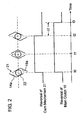
- the cam mechanism 21 When the reversal is brought about in the differential rotation, the cam mechanism 21 once releases the main clutch 16 from the pressuring force and again exerts the pressuring force on the main clutch 16. At this time, the planetary gear mechanism 18 is performing the torque transmission in the following relation shown in Table 1 in dependence on the gear tooth ratio of the ring gear 28 to the sun gear 30.
- the cam mechanism 21 completes the reversal in motion transmission earlier than the main outer and inner clutch plates 16a, 16b complete the reversals in motion transmission through the backlashes at their spline engagement portions with the front housing 11 and the first inner shaft 13. Accordingly, since the reversals of the main outer clutch plates 16a and the main inner clutch plates 16b are completed after the completion in reversal of the cam mechanism 21, the cam mechanism 21 can be prevented from generating the strange noise at the time of completing the reversal in the torque transmission.
- the cam grooves 19a and 14a of the cam ring 19 and the second inner shaft 14 are kept in tight connection as those schematically illustrated at the time point t0.
- the reversal of the cam mechanism 21 begins to release the main clutch 16 from the pressuring force.
- the main clutch 16 is released from the friction engagement and is brought into the reversal at the same time.
- the main clutch 16 is placed in the state of no friction connection.
- the cam mechanism 21 completes the reversal at the time point t2 and again exerts the pressuring force on the main clutch 16.
- the main clutch 16 is still in the course of the reversal, so that the second inner shaft 14 is being permitted to rotate relative to the housing 11.
- the minute time period or time difference ⁇ t is set longer than a fluctuation in time period which may be caused by a dispersion of the backlashes provided in the main clutch 16 and the cam mechanism 19 in the machining processes therefor.
- a differential limiting device 10 for a vehicle is provided with a planetary gear mechanism 18, in which a planetary carrier 27 rotatable bodily with a front housing 11 distributes the rotational power of the front housing 11 to a ring gear 28 and a sun gear 30 through planetary gears 29 and hence, to a first inner shaft 13 and a second inner shaft 14 which are rotatable bodily respectively with the ring gear 28 and the sun gear 30.
- the axial movement of the second inner shaft 14 causes the first inner shaft 13 to be axially moved, whereby a main clutch 16 arranged between the front housing 11 and the first inner shaft 13 is brought into friction engagement.
- the main clutch 16 limits the relative rotation between the ring gear 28 and the planetary carrier 27.
Landscapes
- Engineering & Computer Science (AREA)
- General Engineering & Computer Science (AREA)
- Mechanical Engineering (AREA)
- Physics & Mathematics (AREA)
- Electromagnetism (AREA)
- Retarders (AREA)
- Arrangement And Driving Of Transmission Devices (AREA)
- Mechanical Operated Clutches (AREA)
Applications Claiming Priority (2)
| Application Number | Priority Date | Filing Date | Title |
|---|---|---|---|
| JP2004001838A JP4363188B2 (ja) | 2004-01-07 | 2004-01-07 | 差動制限装置 |
| JP2004001838 | 2004-01-07 |
Publications (2)
| Publication Number | Publication Date |
|---|---|
| EP1577586A1 true EP1577586A1 (fr) | 2005-09-21 |
| EP1577586B1 EP1577586B1 (fr) | 2007-06-20 |
Family
ID=34709020
Family Applications (1)
| Application Number | Title | Priority Date | Filing Date |
|---|---|---|---|
| EP04029664A Expired - Lifetime EP1577586B1 (fr) | 2004-01-07 | 2004-12-15 | Dispositif pour le force limitative d'un différentiel |
Country Status (4)
| Country | Link |
|---|---|
| US (1) | US7144347B2 (fr) |
| EP (1) | EP1577586B1 (fr) |
| JP (1) | JP4363188B2 (fr) |
| DE (1) | DE602004007099T2 (fr) |
Families Citing this family (16)
| Publication number | Priority date | Publication date | Assignee | Title |
|---|---|---|---|---|
| JP2006348983A (ja) * | 2005-06-13 | 2006-12-28 | Fuji Heavy Ind Ltd | 差動制限機構付き差動装置 |
| US7341541B2 (en) * | 2005-10-11 | 2008-03-11 | Chrysler Llc | Method to reduce backlash in a drive train |
| JP4650225B2 (ja) * | 2005-11-15 | 2011-03-16 | 株式会社ジェイテクト | 駆動力伝達装置 |
| WO2007071115A1 (fr) * | 2005-12-23 | 2007-06-28 | Xiaochun Wang | Differentiel interponts a glissement limite a couple divise |
| JP2007315583A (ja) * | 2006-01-31 | 2007-12-06 | Gkn ドライブライン トルクテクノロジー株式会社 | クラッチ装置及びこれを用いたデファレンシャル装置 |
| JP2009085293A (ja) * | 2007-09-28 | 2009-04-23 | Jtekt Corp | 差動制限装置 |
| US8231494B2 (en) * | 2007-11-07 | 2012-07-31 | Borg Warner, Inc. | Active control center differential with front output |
| EP2131069B1 (fr) * | 2008-06-05 | 2011-09-21 | Jtekt Corporation | Appareil différentiel de véhicule |
| US8162791B1 (en) * | 2009-02-17 | 2012-04-24 | Michael Cronin | Transmission for model electric vehicles |
| US8500590B2 (en) * | 2010-06-23 | 2013-08-06 | Borgwarner, Inc. | Electromagnetic clutch disconnect for accessory drive |
| JP5668398B2 (ja) * | 2010-08-30 | 2015-02-12 | 株式会社ジェイテクト | 駆動力伝達装置及び車両 |
| CN103121634B (zh) * | 2011-11-18 | 2015-07-29 | 陈伟 | 恒制动内摆线减速卷扬机 |
| CN103121614B (zh) * | 2011-11-18 | 2015-07-29 | 陈伟 | 永磁恒制动电梯摆线曳引机 |
| WO2014186466A2 (fr) * | 2013-05-14 | 2014-11-20 | Gkn Driveline North America, Inc. | Ensemble dispositif de désolidarisation de différentiel de véhicule |
| CN108237900B (zh) * | 2016-12-27 | 2020-05-22 | 比亚迪股份有限公司 | 驱动轴锁止装置以及动力驱动系统和车辆 |
| CN114735205A (zh) * | 2022-04-25 | 2022-07-12 | 贵州新安航空机械有限责任公司 | 偏心凸轮式操纵手柄机构 |
Citations (8)
| Publication number | Priority date | Publication date | Assignee | Title |
|---|---|---|---|---|
| EP0409610A1 (fr) * | 1989-07-20 | 1991-01-23 | Tochigifujisangyo Kabushiki Kaisha | Dispositif d'embrayage |
| US5156578A (en) * | 1990-06-05 | 1992-10-20 | Tochigifujisangyo Kabushiki Kaisha | Differential gear device for vehicle |
| US5269730A (en) * | 1990-06-05 | 1993-12-14 | Tochigifujisangyo Kabushiki Kaisha | Differential gear device for vehicle |
| US5326333A (en) * | 1991-11-19 | 1994-07-05 | Tochigi Fuji Sangyo Kabushiki Kaisha | Differential apparatus with carrier axially movable relative to an output hub |
| EP0612929A2 (fr) * | 1993-02-26 | 1994-08-31 | Honda Giken Kogyo Kabushiki Kaisha | Dispositif de transmission |
| JPH09144845A (ja) * | 1995-11-21 | 1997-06-03 | Tochigi Fuji Ind Co Ltd | 差動制限装置 |
| US6378677B1 (en) * | 2000-10-03 | 2002-04-30 | Honda Giken Kogyo Kabushiki Kaisha | Power transmission device having electromagnetic clutch |
| US6436002B1 (en) * | 1999-07-12 | 2002-08-20 | Tochigi Fuji Sangyo Kabushiki Kaisha | Differential apparatus |
Family Cites Families (1)
| Publication number | Priority date | Publication date | Assignee | Title |
|---|---|---|---|---|
| JP2001163075A (ja) * | 1999-12-10 | 2001-06-19 | Komatsu Ltd | 2車軸走行駆動トルク伝達装置 |
-
2004
- 2004-01-07 JP JP2004001838A patent/JP4363188B2/ja not_active Expired - Fee Related
- 2004-12-14 US US11/010,268 patent/US7144347B2/en not_active Expired - Lifetime
- 2004-12-15 EP EP04029664A patent/EP1577586B1/fr not_active Expired - Lifetime
- 2004-12-15 DE DE602004007099T patent/DE602004007099T2/de not_active Expired - Lifetime
Patent Citations (8)
| Publication number | Priority date | Publication date | Assignee | Title |
|---|---|---|---|---|
| EP0409610A1 (fr) * | 1989-07-20 | 1991-01-23 | Tochigifujisangyo Kabushiki Kaisha | Dispositif d'embrayage |
| US5156578A (en) * | 1990-06-05 | 1992-10-20 | Tochigifujisangyo Kabushiki Kaisha | Differential gear device for vehicle |
| US5269730A (en) * | 1990-06-05 | 1993-12-14 | Tochigifujisangyo Kabushiki Kaisha | Differential gear device for vehicle |
| US5326333A (en) * | 1991-11-19 | 1994-07-05 | Tochigi Fuji Sangyo Kabushiki Kaisha | Differential apparatus with carrier axially movable relative to an output hub |
| EP0612929A2 (fr) * | 1993-02-26 | 1994-08-31 | Honda Giken Kogyo Kabushiki Kaisha | Dispositif de transmission |
| JPH09144845A (ja) * | 1995-11-21 | 1997-06-03 | Tochigi Fuji Ind Co Ltd | 差動制限装置 |
| US6436002B1 (en) * | 1999-07-12 | 2002-08-20 | Tochigi Fuji Sangyo Kabushiki Kaisha | Differential apparatus |
| US6378677B1 (en) * | 2000-10-03 | 2002-04-30 | Honda Giken Kogyo Kabushiki Kaisha | Power transmission device having electromagnetic clutch |
Non-Patent Citations (1)
| Title |
|---|
| PATENT ABSTRACTS OF JAPAN vol. 1997, no. 10 31 October 1997 (1997-10-31) * |
Also Published As
| Publication number | Publication date |
|---|---|
| DE602004007099D1 (de) | 2007-08-02 |
| EP1577586B1 (fr) | 2007-06-20 |
| DE602004007099T2 (de) | 2008-02-14 |
| US7144347B2 (en) | 2006-12-05 |
| US20050148424A1 (en) | 2005-07-07 |
| JP4363188B2 (ja) | 2009-11-11 |
| JP2005195090A (ja) | 2005-07-21 |
Similar Documents
| Publication | Publication Date | Title |
|---|---|---|
| US7144347B2 (en) | Differential limiting device | |
| US9744851B2 (en) | Transfer for four-wheel drive vehicle | |
| US9057430B2 (en) | Four-wheel drive vehicle | |
| US9695885B2 (en) | Auxiliary drive wheel-side differential unit for four-wheel drive vehicle | |
| CN100432485C (zh) | 齿轮变速装置、驱动装置和车辆 | |
| JP3002040B2 (ja) | デファレンシャル装置 | |
| JP2005516168A (ja) | 連続可変変速装置 | |
| US20130056321A1 (en) | Driving force transmission apparatus | |
| GB2525718A (en) | Disconnecting driveline component | |
| JP6388904B2 (ja) | 車両のための駆動ユニットおよび車両の2つの出力シャフトの間でトルクをシフトさせるための方法 | |
| JP2019535975A (ja) | クラッチアッセンブリおよび駆動アッセンブリ | |
| JPH03248919A (ja) | 動力伝達装置 | |
| JP2004114778A (ja) | 動力伝達装置 | |
| US6637572B2 (en) | Electromagnetic clutch structure in driving force distribution system | |
| JP2014148267A (ja) | 四輪駆動車両 | |
| JP2015140133A (ja) | 車両駆動システム | |
| JP2003039968A (ja) | 動力伝達装置 | |
| JP2010058684A (ja) | 四輪駆動車用駆動力伝達装置 | |
| JP2015148280A (ja) | 車両用多板クラッチ | |
| JP4038033B2 (ja) | 車両の前後輪駆動装置およびクラッチの切換方法 | |
| JP2005059683A (ja) | ハイブリッド車両の動力伝達装置 | |
| WO2014091621A1 (fr) | Dispositif d'interruption et dispositif de transmission de puissance utilisant ledit dispositif d'interruption | |
| JP4353606B2 (ja) | 発進クラッチ | |
| JP2662473B2 (ja) | センタデフロック装置 | |
| JP2950568B2 (ja) | 動力伝達装置 |
Legal Events
| Date | Code | Title | Description |
|---|---|---|---|
| PUAI | Public reference made under article 153(3) epc to a published international application that has entered the european phase |
Free format text: ORIGINAL CODE: 0009012 |
|
| AK | Designated contracting states |
Kind code of ref document: A1 Designated state(s): AT BE BG CH CY CZ DE DK EE ES FI FR GB GR HU IE IS IT LI LT LU MC NL PL PT RO SE SI SK TR |
|
| AX | Request for extension of the european patent |
Extension state: AL BA HR LV MK YU |
|
| 17P | Request for examination filed |
Effective date: 20060320 |
|
| AKX | Designation fees paid |
Designated state(s): DE FR GB |
|
| RAP1 | Party data changed (applicant data changed or rights of an application transferred) |
Owner name: JTEKT CORPORATION |
|
| RIN1 | Information on inventor provided before grant (corrected) |
Inventor name: KUSHINO, HIROSHI C/O JTEKT CORPORATION |
|
| GRAP | Despatch of communication of intention to grant a patent |
Free format text: ORIGINAL CODE: EPIDOSNIGR1 |
|
| GRAS | Grant fee paid |
Free format text: ORIGINAL CODE: EPIDOSNIGR3 |
|
| GRAA | (expected) grant |
Free format text: ORIGINAL CODE: 0009210 |
|
| AK | Designated contracting states |
Kind code of ref document: B1 Designated state(s): DE FR GB |
|
| REG | Reference to a national code |
Ref country code: GB Ref legal event code: FG4D |
|
| REF | Corresponds to: |
Ref document number: 602004007099 Country of ref document: DE Date of ref document: 20070802 Kind code of ref document: P |
|
| ET | Fr: translation filed | ||
| PLBE | No opposition filed within time limit |
Free format text: ORIGINAL CODE: 0009261 |
|
| STAA | Information on the status of an ep patent application or granted ep patent |
Free format text: STATUS: NO OPPOSITION FILED WITHIN TIME LIMIT |
|
| 26N | No opposition filed |
Effective date: 20080325 |
|
| GBPC | Gb: european patent ceased through non-payment of renewal fee |
Effective date: 20081215 |
|
| PG25 | Lapsed in a contracting state [announced via postgrant information from national office to epo] |
Ref country code: GB Free format text: LAPSE BECAUSE OF NON-PAYMENT OF DUE FEES Effective date: 20081215 |
|
| PGFP | Annual fee paid to national office [announced via postgrant information from national office to epo] |
Ref country code: FR Payment date: 20141208 Year of fee payment: 11 |
|
| REG | Reference to a national code |
Ref country code: FR Ref legal event code: ST Effective date: 20160831 |
|
| PG25 | Lapsed in a contracting state [announced via postgrant information from national office to epo] |
Ref country code: FR Free format text: LAPSE BECAUSE OF NON-PAYMENT OF DUE FEES Effective date: 20151231 |
|
| PGFP | Annual fee paid to national office [announced via postgrant information from national office to epo] |
Ref country code: DE Payment date: 20171212 Year of fee payment: 14 |
|
| REG | Reference to a national code |
Ref country code: DE Ref legal event code: R119 Ref document number: 602004007099 Country of ref document: DE |
|
| PG25 | Lapsed in a contracting state [announced via postgrant information from national office to epo] |
Ref country code: DE Free format text: LAPSE BECAUSE OF NON-PAYMENT OF DUE FEES Effective date: 20190702 |