EP1577592A1 - Vanne coulissante - Google Patents
Vanne coulissante Download PDFInfo
- Publication number
- EP1577592A1 EP1577592A1 EP04006114A EP04006114A EP1577592A1 EP 1577592 A1 EP1577592 A1 EP 1577592A1 EP 04006114 A EP04006114 A EP 04006114A EP 04006114 A EP04006114 A EP 04006114A EP 1577592 A1 EP1577592 A1 EP 1577592A1
- Authority
- EP
- European Patent Office
- Prior art keywords
- slide plate
- opening
- slide
- valve according
- housing
- Prior art date
- Legal status (The legal status is an assumption and is not a legal conclusion. Google has not performed a legal analysis and makes no representation as to the accuracy of the status listed.)
- Granted
Links
- 238000000576 coating method Methods 0.000 claims abstract description 20
- 239000011248 coating agent Substances 0.000 claims abstract description 19
- 238000007789 sealing Methods 0.000 claims description 45
- 239000000758 substrate Substances 0.000 claims description 13
- 239000012530 fluid Substances 0.000 claims description 2
- 150000001875 compounds Chemical class 0.000 claims 1
- 238000007598 dipping method Methods 0.000 claims 1
- 230000000149 penetrating effect Effects 0.000 claims 1
- 230000008901 benefit Effects 0.000 description 4
- 239000011521 glass Substances 0.000 description 4
- 230000007704 transition Effects 0.000 description 4
- 230000000284 resting effect Effects 0.000 description 3
- 230000000694 effects Effects 0.000 description 2
- 238000009434 installation Methods 0.000 description 2
- 238000012423 maintenance Methods 0.000 description 2
- 239000002184 metal Substances 0.000 description 2
- 239000002245 particle Substances 0.000 description 2
- 238000009827 uniform distribution Methods 0.000 description 2
- 230000004913 activation Effects 0.000 description 1
- 238000011161 development Methods 0.000 description 1
- 230000018109 developmental process Effects 0.000 description 1
- 230000004069 differentiation Effects 0.000 description 1
- 239000013013 elastic material Substances 0.000 description 1
- 239000005357 flat glass Substances 0.000 description 1
- 239000011888 foil Substances 0.000 description 1
- 230000007774 longterm Effects 0.000 description 1
- -1 magnetic tapes Substances 0.000 description 1
- 239000000203 mixture Substances 0.000 description 1
- 239000004033 plastic Substances 0.000 description 1
- 239000002985 plastic film Substances 0.000 description 1
- 229920006255 plastic film Polymers 0.000 description 1
- 238000003825 pressing Methods 0.000 description 1
- 230000009467 reduction Effects 0.000 description 1
- 238000004544 sputter deposition Methods 0.000 description 1
- 238000011144 upstream manufacturing Methods 0.000 description 1
Images

Classifications
-
- F—MECHANICAL ENGINEERING; LIGHTING; HEATING; WEAPONS; BLASTING
- F16—ENGINEERING ELEMENTS AND UNITS; GENERAL MEASURES FOR PRODUCING AND MAINTAINING EFFECTIVE FUNCTIONING OF MACHINES OR INSTALLATIONS; THERMAL INSULATION IN GENERAL
- F16K—VALVES; TAPS; COCKS; ACTUATING-FLOATS; DEVICES FOR VENTING OR AERATING
- F16K3/00—Gate valves or sliding valves, i.e. cut-off apparatus with closing members having a sliding movement along the seat for opening and closing
- F16K3/02—Gate valves or sliding valves, i.e. cut-off apparatus with closing members having a sliding movement along the seat for opening and closing with flat sealing faces; Packings therefor
- F16K3/16—Gate valves or sliding valves, i.e. cut-off apparatus with closing members having a sliding movement along the seat for opening and closing with flat sealing faces; Packings therefor with special arrangements for separating the sealing faces or for pressing them together
- F16K3/20—Gate valves or sliding valves, i.e. cut-off apparatus with closing members having a sliding movement along the seat for opening and closing with flat sealing faces; Packings therefor with special arrangements for separating the sealing faces or for pressing them together by movement of the seats
- F16K3/207—Gate valves or sliding valves, i.e. cut-off apparatus with closing members having a sliding movement along the seat for opening and closing with flat sealing faces; Packings therefor with special arrangements for separating the sealing faces or for pressing them together by movement of the seats by means of hydraulic forces
-
- F—MECHANICAL ENGINEERING; LIGHTING; HEATING; WEAPONS; BLASTING
- F16—ENGINEERING ELEMENTS AND UNITS; GENERAL MEASURES FOR PRODUCING AND MAINTAINING EFFECTIVE FUNCTIONING OF MACHINES OR INSTALLATIONS; THERMAL INSULATION IN GENERAL
- F16K—VALVES; TAPS; COCKS; ACTUATING-FLOATS; DEVICES FOR VENTING OR AERATING
- F16K27/00—Construction of housing; Use of materials therefor
- F16K27/02—Construction of housing; Use of materials therefor of lift valves
-
- F—MECHANICAL ENGINEERING; LIGHTING; HEATING; WEAPONS; BLASTING
- F16—ENGINEERING ELEMENTS AND UNITS; GENERAL MEASURES FOR PRODUCING AND MAINTAINING EFFECTIVE FUNCTIONING OF MACHINES OR INSTALLATIONS; THERMAL INSULATION IN GENERAL
- F16K—VALVES; TAPS; COCKS; ACTUATING-FLOATS; DEVICES FOR VENTING OR AERATING
- F16K3/00—Gate valves or sliding valves, i.e. cut-off apparatus with closing members having a sliding movement along the seat for opening and closing
- F16K3/02—Gate valves or sliding valves, i.e. cut-off apparatus with closing members having a sliding movement along the seat for opening and closing with flat sealing faces; Packings therefor
- F16K3/0281—Guillotine or blade-type valves, e.g. no passage through the valve member
-
- F—MECHANICAL ENGINEERING; LIGHTING; HEATING; WEAPONS; BLASTING
- F16—ENGINEERING ELEMENTS AND UNITS; GENERAL MEASURES FOR PRODUCING AND MAINTAINING EFFECTIVE FUNCTIONING OF MACHINES OR INSTALLATIONS; THERMAL INSULATION IN GENERAL
- F16K—VALVES; TAPS; COCKS; ACTUATING-FLOATS; DEVICES FOR VENTING OR AERATING
- F16K3/00—Gate valves or sliding valves, i.e. cut-off apparatus with closing members having a sliding movement along the seat for opening and closing
- F16K3/30—Details
- F16K3/314—Forms or constructions of slides; Attachment of the slide to the spindle
Definitions
- the invention relates to a slide valve having the features of the preamble of Patent claim 1, as well as on a coating system with such a valve.
- valves are often installed in continuous coating systems, which are used for Coating flexible tape substrates, e.g. As plastic films, magnetic tapes, films etc., or even of rigid substrates such as plastic or glass panes, serve in a vacuum.
- Rigid substrates lie on rolls and pass between loading and unloading stations transported, which in turn are regularly ventilated.
- Such continuous coating systems are basically subdivided into modules (Loading, coating and Auslademodul) arranged successively and are connected by openings through which the substrate in the next following Module is guided.
- valves do not have to switch constantly back and forth, but are ultimately only used or activated during charge changes or other system downtime, but then have to seal the pressure difference between atmospheric pressure and vacuum.
- the installation position of these valves is inevitably directly in the area of the substrate transport systems.
- these transport systems are usually designed as roller conveyors with defined roller distances. Due to ever-increasing customer requirements, such as ever smaller substrate dimensions and increasing throughput speeds, it is necessary to shorten the distances between the individual transport rollers to each other accordingly. This fact requires a very narrow separating valve, since it has to be accommodated between two transport rollers, with one transport roller in one module (upstream) and the next transport roller in the other module (downstream).
- the generic document DE 198 57 201 A1 describes such a flat-building Gate valve for simultaneously shutting off or releasing two between two vacuum chambers provided, aligned passage openings, which has a low Height and have a large width.
- the valve is for continuous systems for coating designed from large glass formats.
- a short-stroke further fluidic (pneumatic) closing drive the pressurized after the spool plates have been moved to their working position and the two plates spread apart until they are in their closed position at the same time abut against each associated with them, surrounding the openings sealing surfaces and the Close openings thus tightly.
- the reaction forces of the closing drive are each removed over the opposite valve plate.
- U.S. Patent No. 4,157,169 discloses another, in principle very similar to that discussed above constructed lock valve, the opening and closing two round passages is provided.
- the invention is based on the object, a particularly flat-built slide valve create that for the installation in particular between two close successive roles a continuous coating plant is suitable and nevertheless very high pressure differences endures and reliably seals, with its moving parts as simple as possible should be built.
- the invention describes a valve, preferably either as a maintenance valve or as Valve with a small number of cycles is used, so are not switched very often got to.
- the structure is similar to a slide valve with a very flat design (max. 50mm), which is vacuum-tight on both sides. Due to its active principle, it is also possible, also slit-shaped To reliably seal openings with a very long length. Likewise, the valve is in able to compensate for large-wave unevenness of the opening to be closed achieved due to the very flexible design of its slide plate.
- the plate is closed by means of a housing-fixed closing drive pressed down a housing wall, on which the corresponding sealing surface is located.
- Reaction forces of the closing drive are thus advantageously directly within the fixed housing ablated.
- the closing movement of the valve according to the invention or its slide plate runs angular, preferably at right angles to the adjusting movement between the rest position and the working position of its slide plate.
- the slide valve according to the invention is mirror-symmetrical with each built two closing drives and two sealing surfaces, making it two different Closed positions can take.
- the slide valve depending on the direction of the pressure difference across the slide plate be selectively closed so that the respective greater pressure on one Side the sealing effect even stronger.
- the slide plate is pendulum suspended in the sealing direction, thus in the adjusting movements between resting and working position substantially free of friction; this reduces or also avoids wear on the sealing surfaces.
- “commuting” is no Agility over longer distances or strokes to understand. Rather, the slide plate has transverse to the direction of adjustment between rest and working position certain degrees of freedom, which are rather to be regarded as a limited side game. It can be reliable
- the function of the slide valve is sufficient, the slide plate by a few tenths Millimeter from their work in their respective sealing position to move or deflect.
- the closing drives are preferably activated by fluid pressure, d. H. they include at least one provided with a pressure port closed space with at least a movable wall. It is not essential that these locking drives themselves completely to extend the entire opening, but you can basically provide a subdivided into several sections or individual actuators closing drive (as similarly described in the generic state of the art). In this Execution case is of course a uniform distribution of the individual drive parts along to the extent of the opening to be closed, although not necessarily functionally necessary.
- annularly closed, tubular tire-like design is particularly preferred the closing drive, especially since it is in this version as an additional Apply sealing ring to the smooth-walled slide plate and thus z.
- the closing drive also the (unwanted) Application of coating particles coming from the vacuum chamber into the opening and can get to the valve (also called overspray) on the actual sealing rings prevented.
- the closing drives and the corresponding seals are arranged on concentric parallel tracks around the openings to be closed, whereby the closing drives can be arranged outside or within the surfaces circumscribed by these seals.
- the closing drives protect the sealing rings, as already mentioned, as far as possible from unwanted deposits.
- this version with a simple, smooth slide plate has the big one Advantage that long-wave unevenness of the sealing surfaces by intrinsic flexibility of the large area and pressed over the entire circumference of the opening to be closed Sliding plate can be compensated, so that even slight distortion of the sealing seat due to dimensional or surface deviations or uneven tightening of Screws, etc., not necessarily to leaks of the slide valve according to the invention to lead.
- very large, slot-like openings of several Meters wide, the z For example, in continuous coating systems for more than 3 m wide glass plates are common and necessary, certainly against the pressure differences between vacuum and atmospheric pressure to be completed.
- each one Closing drive forms a mixture of drive member and sealing surface.
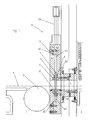
- This cross-section shows the transition between two modules 1, 2 of a continuous coating plant. It is assumed that (here only by a horizontal transport plane T) substrates undergo this transition from left to right, wherein they are supported by closely spaced rollers 3 (in the relatively short shown section of the system, however, only a role 3 is shown schematically).
- an opening 4 is provided which is perpendicular to Drawing plane can have significantly larger dimensions than in their visible here Height, so can be considered as slit-shaped, but overall with the smallest possible free cross section is executed. It just has to be in the preferred use case be large enough to pass through flat glass plates more than 3 m wide.
- the slide valve 5 initially comprises a housing 6 with two housing parts 6.1 and 6.2. It is understood that this housing 6 is very well sealed in itself, as far as it is composed of different components. One recognizes here z. B. a sealing ring 6D in the joint between the two housing parts 6.1 and 6.2, and another sealing ring 6D in the joint between the housing part 6.2 and the wall of the transition to which the housing 6 is clamped in the region of the opening 4 total.
- the housing 6 is also penetrated in total by the opening 4 or it has a channel which forms a continuation of said opening 4 with a constant free cross-section.
- this slide valve does not have to be arranged between the two modules 1 and 2, but that its housing 6 is screwed on one side to the wall of the module 1. This will be a certain Reduction of the distance between the two modules possible. Nevertheless, it is natural depending on the type of plant and available space, the valve according to the invention also possible to install in a joint, a gap or transition between two modules, wherein its channel between the two directly interconnected openings of the Modules would come to rest.
- the two housing parts 6.1 and 6.2 form between them a guide slot 6 S, in the a slide plate 7 oscillating, d. H. seen in the normal direction to their major surfaces is stored with little lateral play. It hangs on a not shown translatory actuator 7A.
- actuator 7A is with the slide plate 7 in a suitable manner connected to allow their lateral deflections.
- This connection between the actuator 7A and the slide plate 7 penetrates the housing 6. Special sealing measures are required at this point only if the actuator 7A itself should be outside the module 1 or outside the evacuable volume.
- the (vertical) guide slot 6S extends, as well as the recorded in it Slide plate, transverse to the (horizontal) axis of the opening 4, in sections on both sides of the transport plane T. Its substantial length portion is above the Transport level T, but is also provided below a short section.
- the slide plate 7 by means of the actuator 7A out and forth adjustable, between a rest position (see Fig. 2), in which the opening is completely open and substrates can pass through it, and the work shown here is or closed position in which the slide plate 7, the slot-shaped opening 4 completely covers.
- the slide plate 7 In the rest position, the slide plate 7 is completely in the upper part of the guide slot 6S recorded, in the working position their lower edge dives like a blade in the lower Section of the guide slot 6S, while its upper part still in the upper Section remains. It is essential that the slide plate 7 everywhere the edge of the opening 4 covered.
- the reciprocating movement of the slide plate 7 by means of the actuator 7A takes place first free, without too tight guide in the guide slot 6S, d. H. also with negligible Friction. Consequently, the actuator 7A does not have to apply too high actuating forces.
- He may be, for example, a pneumatic or hydraulic lift cylinder, a rack drive, or an electromagnetic linear motor. He does not have to run a long stroke (a few inches) and the sealing plate only has to be relatively coarse in its working position can position.
- the actuator 7A is representative of a plurality of similar, Synchronously controllable actuators is, which are used when needed, if the Slide plate 7 extends possibly over several meters in length perpendicular to the plane of the drawing.
- a first closing drive 8 is inserted in the left half of the housing 6.1. He is preferable designed as an inflatable seal, which in a circumferential annular groove of the housing wall is inserted and in turn surrounds the entire circumference of the opening 4. Functionally corresponds with this closing drive 8, a ring seal 9, in the wall of the opposite Housing half 6.2 is also embedded in an annular groove and also the opening 4 completely surrounds.
- the closing drive 8 in the illustrated embodiment is in the opposite lying wall of the housing part 6.2, a second closing drive 10 of the same type as the Closed drive 8 embedded. It is within the circumscribed by the ring seal 9 Area.
- the closing drive 10 in turn functionally corresponds to a ring seal 11, the in the wall of the housing part 6.1 is inserted, again exactly opposite the ring seal 9, and surrounds the closing drive 8.
- the closing drives 8 and / or 10 as uniform, schlauchsammlungartig circulating chambers interpret. It is special also conceivable, the closing drives instead of revolving only as two parallel elongated sections on both sides of the opening 4. Even that would be even more essential Protection of the sealing rings against overspray guaranteed.
- only one of the closing drives can be provided, if only in one direction, the slide plate is designed to seal.
- the circumferential configuration of the closing drives 8 and 10 discussed here has the Advantage that they with appropriate design of their outer surfaces as secondary seals on the smooth surface of the slide plate 7 abut and thus the sealing effect of the sealing rings 9 or 11 still support as long as their interior is pressurized.
- a strip 12 of permanently elastic material interchangeably attached He closes the section of the guide slot 6S below the transport plane and prevents the falling of particles in the lower portion of the guide slot 6S. It is designed as a lip seal divided and leaves the slide plate 7 unhindered immerse yourself when it is put into its working position.
- sealing rings 9 and 11 and the closing drives 8 and 10 respectively are far in the respective housing walls embedded or optionally by negative pressure Retractable are that damage or even friction due to contacts with the slide plate 7 during their Umstellieri between rest and working position can be excluded.
- the slide plate 7 in comparison with the thicknesses of the housing parts 6.1 and 6.2 can be kept quite thin and light. In cooperation with a uniform distribution as possible of the closing forces acting from the closing drives 8 and 10, respectively, the slide plate 7 will thus be able to conform exactly to the course of the sealing rings 9 and 11, even if these should have slight long-wave deviations from the ideal sealing plane. As a rule, the slide plate 7 is then actuated by the drive 7A when the pressure in both modules to be separated from each other is (still or again) the same, ie, for. B. atmospheric pressure on both sides or vacuum on both sides.
- closing drives 8 and 10 are the actual valve drives, which ensure the sealing function.
- the actuator 7A is for positioning only the slide plate provided in their general working position, regardless of the Direction of pressure difference.
- the actual sealing function of the slide valve 6 or the one-piece slide plate 7 are used here in both directions, by optionally one of the closing drives 8 or 10 is actuated.
- the exemplary embodiment of the slide valve described and shown here 6 is constructed mirror-symmetrically in its parts with sealing function and therefore in both directions a high pressure difference across the plane of the slide plate 7 endure can.
- the actuator can 7A return the slide plate to its rest position. Possibly. can solve the Slide plate 7 of the sealing rings 9 or 11 by means not shown here leaf or Disc springs are supported, of course, the restoring force of the closing drives must be overcome.
- slide valve according to the invention even if it is based on a preferred embodiment for continuous coating systems for large individual substrates has been described, regardless of this use also used elsewhere can be.
Landscapes
- Engineering & Computer Science (AREA)
- General Engineering & Computer Science (AREA)
- Mechanical Engineering (AREA)
- Sliding Valves (AREA)
- Details Of Valves (AREA)
- Valve Device For Special Equipments (AREA)
- Magnetically Actuated Valves (AREA)
- Electronic Switches (AREA)
- Physical Vapour Deposition (AREA)
- Valve-Gear Or Valve Arrangements (AREA)
- Multiple-Way Valves (AREA)
Priority Applications (12)
| Application Number | Priority Date | Filing Date | Title |
|---|---|---|---|
| DE202004005217U DE202004005217U1 (de) | 2004-03-15 | 2004-03-15 | Schieberventil |
| EP04006114A EP1577592B1 (fr) | 2004-03-15 | 2004-03-15 | Vanne coulissante |
| PL04006114T PL1577592T3 (pl) | 2004-03-15 | 2004-03-15 | Zawór suwakowy |
| PT04006114T PT1577592E (pt) | 2004-03-15 | 2004-03-15 | Válvula de corrediça |
| ES04006114T ES2305598T3 (es) | 2004-03-15 | 2004-03-15 | Valvula de compuerta. |
| AT04006114T ATE391874T1 (de) | 2004-03-15 | 2004-03-15 | Schieberventil |
| DE502004006768T DE502004006768D1 (de) | 2004-03-15 | 2004-03-15 | Schieberventil |
| TW093122261A TWI320832B (en) | 2004-03-15 | 2004-07-26 | Slide valve |
| KR1020040063553A KR100683482B1 (ko) | 2004-03-15 | 2004-08-12 | 슬라이드밸브 |
| US10/928,326 US7114702B2 (en) | 2004-03-15 | 2004-08-27 | Slide valve |
| JP2004306377A JP4095984B2 (ja) | 2004-03-15 | 2004-10-21 | スライド弁 |
| CNB2004101014597A CN100510487C (zh) | 2004-03-15 | 2004-12-16 | 滑阀 |
Applications Claiming Priority (1)
| Application Number | Priority Date | Filing Date | Title |
|---|---|---|---|
| EP04006114A EP1577592B1 (fr) | 2004-03-15 | 2004-03-15 | Vanne coulissante |
Publications (2)
| Publication Number | Publication Date |
|---|---|
| EP1577592A1 true EP1577592A1 (fr) | 2005-09-21 |
| EP1577592B1 EP1577592B1 (fr) | 2008-04-09 |
Family
ID=34833601
Family Applications (1)
| Application Number | Title | Priority Date | Filing Date |
|---|---|---|---|
| EP04006114A Expired - Lifetime EP1577592B1 (fr) | 2004-03-15 | 2004-03-15 | Vanne coulissante |
Country Status (11)
| Country | Link |
|---|---|
| US (1) | US7114702B2 (fr) |
| EP (1) | EP1577592B1 (fr) |
| JP (1) | JP4095984B2 (fr) |
| KR (1) | KR100683482B1 (fr) |
| CN (1) | CN100510487C (fr) |
| AT (1) | ATE391874T1 (fr) |
| DE (2) | DE202004005217U1 (fr) |
| ES (1) | ES2305598T3 (fr) |
| PL (1) | PL1577592T3 (fr) |
| PT (1) | PT1577592E (fr) |
| TW (1) | TWI320832B (fr) |
Cited By (2)
| Publication number | Priority date | Publication date | Assignee | Title |
|---|---|---|---|---|
| CN103899762A (zh) * | 2012-12-27 | 2014-07-02 | Vat控股公司 | 真空滑阀 |
| WO2017174448A1 (fr) * | 2016-04-08 | 2017-10-12 | Vat Holding Ag | Dispositif de fermeture |
Families Citing this family (21)
| Publication number | Priority date | Publication date | Assignee | Title |
|---|---|---|---|---|
| ATE360180T1 (de) * | 2004-03-15 | 2007-05-15 | Applied Materials Gmbh & Co Kg | Vakuumbehandlungsanlage mit umsetzbarem wartungsventil |
| EP1698715A1 (fr) * | 2005-03-03 | 2006-09-06 | Applied Films GmbH & Co. KG | machine de revêtement ayant des élèments sur un tiroir |
| DE102006043813B4 (de) * | 2006-02-21 | 2011-05-19 | Von Ardenne Anlagentechnik Gmbh | Schieberventil für eine Beschichtungsanlage und Beschichtungsanlage |
| FR2901006B1 (fr) * | 2006-05-09 | 2008-07-18 | Peugeot Citroen Automobiles Sa | Valve et systeme de limitation de debit d'air entrant de pompe a vide d'un vehicule |
| EP2057403B1 (fr) * | 2006-08-28 | 2016-05-25 | Liqui-Box Canada Inc. | Raccord de soupape à tiroir et collier |
| DE202006015750U1 (de) * | 2006-10-13 | 2007-11-29 | Hawle Armaturen Gmbh | Einsatzeinrichtung zum Einsetzen in eine Leitung oder Absperrarmatur sowie entsprechende Armatur mit dieser |
| US20080213071A1 (en) * | 2007-02-09 | 2008-09-04 | Applied Materials, Inc. | Transport device in an installation for the treatment of substrates |
| USD619219S1 (en) * | 2008-08-26 | 2010-07-06 | Evan Waymire | Dual port slide valve |
| USD641832S1 (en) * | 2008-12-29 | 2011-07-19 | Liqui-Box Corporation | Slider valve fitment |
| USD625390S1 (en) * | 2010-02-18 | 2010-10-12 | Max Widenmann Kg Armaturenfabrik | Slide valve |
| US8511639B2 (en) | 2010-11-15 | 2013-08-20 | Liqui-Box Corporation | Adaptor for use with a valve fitment |
| WO2013077053A1 (fr) * | 2011-11-22 | 2013-05-30 | 株式会社アイエイアイ | Actionneur |
| JP5584751B2 (ja) * | 2012-12-18 | 2014-09-03 | 本田技研工業株式会社 | スプールバルブ |
| DE102014001726A1 (de) * | 2014-02-07 | 2015-08-13 | Walter Kramer | Schieberventil |
| DE102014106001B4 (de) * | 2014-04-29 | 2022-09-29 | Z & J Technologies Gmbh | Leitrohrschieber für chemische und petrochemische Anlagen |
| CN106968224B (zh) * | 2017-05-31 | 2019-05-03 | 国家电网公司 | 抽水蓄能电站上库事故闸门锁定钢梁自动投退装置 |
| CN107524856B (zh) * | 2017-09-21 | 2019-02-19 | 安徽荣达阀门有限公司 | 一种全密封零泄露球阀 |
| CN108006244A (zh) * | 2017-12-29 | 2018-05-08 | 福建龙净脱硫脱硝工程有限公司 | 一种插板阀 |
| CN110959085B (zh) | 2018-06-12 | 2021-02-12 | 株式会社爱发科 | 闸阀装置 |
| GB2641061A (en) * | 2024-05-14 | 2025-11-19 | Woodward Peter | Valve |
| CN121474348B (zh) * | 2026-01-09 | 2026-03-24 | 浙江工业大学 | 一种基于滑阀机构的自适应智能调控唇形密封装置 |
Citations (6)
| Publication number | Priority date | Publication date | Assignee | Title |
|---|---|---|---|---|
| GB851732A (en) * | 1957-07-15 | 1960-10-19 | Vickers Electrical Co Ltd | Improvements relating to fluid control valves |
| FR2283375A1 (fr) * | 1974-07-15 | 1976-03-26 | Commissariat Energie Atomique | Vanne a tiroir pour ultra-vide |
| US4157169A (en) | 1977-10-12 | 1979-06-05 | Torr Vacuum Products | Fluid operated gate valve for use with vacuum equipment |
| FR2500103A2 (fr) * | 1974-04-09 | 1982-08-20 | Socea Balency | Vanne a registre coulissant, notamment pour le transport par voie pneumatique des ordures menageres |
| DE4446946C1 (de) | 1994-12-28 | 1996-09-12 | Vat Holding Ag | Schieberventil |
| DE19857201A1 (de) | 1998-12-11 | 2000-06-15 | Leybold Systems Gmbh | Schleusenventil |
Family Cites Families (14)
| Publication number | Priority date | Publication date | Assignee | Title |
|---|---|---|---|---|
| US2732170A (en) * | 1956-01-24 | Valves | ||
| US2496451A (en) | 1948-03-29 | 1950-02-07 | Mcevoy Co | Refinery valve |
| FR1089995A (fr) * | 1953-07-06 | 1955-03-25 | Ile D Etude Hydrac Soc Civ | Dispositif d'obturation, notamment pour conduits de fluide |
| US3367625A (en) * | 1965-06-22 | 1968-02-06 | Fortune Ronald | Slide gate valves |
| US3321176A (en) * | 1965-08-02 | 1967-05-23 | Jr Thomas J Bolling | Closed fluid system for sealing valve closure elements |
| US3497177A (en) * | 1967-11-02 | 1970-02-24 | Eldon E Hulsey | Seat and seal assembly for valves |
| JPS5115233A (ja) | 1974-07-25 | 1976-02-06 | Ichinose Barubu Kk | Suruusuparubu |
| US4136710A (en) * | 1977-10-11 | 1979-01-30 | Acf Industries, Incorporated | Floating seat structure for gate valves |
| US4292992A (en) * | 1979-07-23 | 1981-10-06 | Allis-Chalmers Corporation | Valve for handling solids capable of gas-pressure-tight closure against a gas pressure differential |
| JPS60136671A (ja) | 1983-12-26 | 1985-07-20 | Fuji Seikou Kk | ゲ−トバルブのシ−ル構造 |
| US4561472A (en) * | 1984-03-20 | 1985-12-31 | Ecolaire Incorporated | Sliding blade closure apparatus with inflatable sealing ring |
| JPH06331044A (ja) * | 1993-05-18 | 1994-11-29 | Kubota Corp | マルチポートスルーコンジットバルブ |
| JP2956739B2 (ja) * | 1993-06-23 | 1999-10-04 | 株式会社クボタ | 高温スライド弁 |
| US6390448B1 (en) * | 2000-03-30 | 2002-05-21 | Lam Research Corporation | Single shaft dual cradle vacuum slot valve |
-
2004
- 2004-03-15 PT PT04006114T patent/PT1577592E/pt unknown
- 2004-03-15 PL PL04006114T patent/PL1577592T3/pl unknown
- 2004-03-15 EP EP04006114A patent/EP1577592B1/fr not_active Expired - Lifetime
- 2004-03-15 ES ES04006114T patent/ES2305598T3/es not_active Expired - Lifetime
- 2004-03-15 DE DE202004005217U patent/DE202004005217U1/de not_active Expired - Lifetime
- 2004-03-15 AT AT04006114T patent/ATE391874T1/de not_active IP Right Cessation
- 2004-03-15 DE DE502004006768T patent/DE502004006768D1/de not_active Expired - Lifetime
- 2004-07-26 TW TW093122261A patent/TWI320832B/zh not_active IP Right Cessation
- 2004-08-12 KR KR1020040063553A patent/KR100683482B1/ko not_active Expired - Fee Related
- 2004-08-27 US US10/928,326 patent/US7114702B2/en not_active Expired - Fee Related
- 2004-10-21 JP JP2004306377A patent/JP4095984B2/ja not_active Expired - Lifetime
- 2004-12-16 CN CNB2004101014597A patent/CN100510487C/zh not_active Expired - Fee Related
Patent Citations (6)
| Publication number | Priority date | Publication date | Assignee | Title |
|---|---|---|---|---|
| GB851732A (en) * | 1957-07-15 | 1960-10-19 | Vickers Electrical Co Ltd | Improvements relating to fluid control valves |
| FR2500103A2 (fr) * | 1974-04-09 | 1982-08-20 | Socea Balency | Vanne a registre coulissant, notamment pour le transport par voie pneumatique des ordures menageres |
| FR2283375A1 (fr) * | 1974-07-15 | 1976-03-26 | Commissariat Energie Atomique | Vanne a tiroir pour ultra-vide |
| US4157169A (en) | 1977-10-12 | 1979-06-05 | Torr Vacuum Products | Fluid operated gate valve for use with vacuum equipment |
| DE4446946C1 (de) | 1994-12-28 | 1996-09-12 | Vat Holding Ag | Schieberventil |
| DE19857201A1 (de) | 1998-12-11 | 2000-06-15 | Leybold Systems Gmbh | Schleusenventil |
Cited By (5)
| Publication number | Priority date | Publication date | Assignee | Title |
|---|---|---|---|---|
| CN103899762A (zh) * | 2012-12-27 | 2014-07-02 | Vat控股公司 | 真空滑阀 |
| US9791052B2 (en) | 2012-12-27 | 2017-10-17 | Vat Holding Ag | Vacuum slide gate valve |
| CN103899762B (zh) * | 2012-12-27 | 2018-05-15 | Vat控股公司 | 真空滑阀 |
| WO2017174448A1 (fr) * | 2016-04-08 | 2017-10-12 | Vat Holding Ag | Dispositif de fermeture |
| US10890262B2 (en) | 2016-04-08 | 2021-01-12 | Vat Holding Ag | Closure device |
Also Published As
| Publication number | Publication date |
|---|---|
| CN1670409A (zh) | 2005-09-21 |
| DE202004005217U1 (de) | 2004-07-15 |
| JP2005265177A (ja) | 2005-09-29 |
| EP1577592B1 (fr) | 2008-04-09 |
| US20050199849A1 (en) | 2005-09-15 |
| KR100683482B1 (ko) | 2007-02-15 |
| TW200530526A (en) | 2005-09-16 |
| PT1577592E (pt) | 2008-07-11 |
| JP4095984B2 (ja) | 2008-06-04 |
| DE502004006768D1 (de) | 2008-05-21 |
| ES2305598T3 (es) | 2008-11-01 |
| PL1577592T3 (pl) | 2008-09-30 |
| ATE391874T1 (de) | 2008-04-15 |
| KR20050092334A (ko) | 2005-09-21 |
| CN100510487C (zh) | 2009-07-08 |
| US7114702B2 (en) | 2006-10-03 |
| TWI320832B (en) | 2010-02-21 |
Similar Documents
| Publication | Publication Date | Title |
|---|---|---|
| EP1577592A1 (fr) | Vanne coulissante | |
| EP2215387B1 (fr) | Soupape de dépression | |
| DE102010053411B4 (de) | Vakuumventil | |
| EP0555764A1 (fr) | Appareillage de traitement sous vide | |
| EP0568950A1 (fr) | Vanne à roue cellulaire | |
| DE4020513C3 (de) | Vorrichtung zur Beförderung von Feststoffe enthaltendem Material zwischen Räumen unterschiedlichen Drucks | |
| EP1582832B1 (fr) | Système de traitement sous vide avec vanne détachable | |
| EP0026401A1 (fr) | Dispositif pour exercer une pression sur la surface de pièces à travailler en mouvement | |
| WO2014060468A1 (fr) | Dispositif de revêtement multicouches pour substrats en bande et installation de revêtement sous vide de substrats en bande | |
| EP1561837B1 (fr) | Installation de revêtement des bandes avec une chambre à vide et un cylindre de revêtement | |
| EP0163820A1 (fr) | Installation de compression sur des pièces en mouvement continu | |
| EP0135042B1 (fr) | Dispositif de vanne à tiroir | |
| DE2937971A1 (de) | Vorrichtung zum aufbringen einer flaechenpressung auf fortschreitende werkstuecke | |
| EP1747301B1 (fr) | Installation de traitement de bande | |
| EP2420459B1 (fr) | Transporteur à dépression, notamment pour le transport d'objets plats | |
| DE2904248A1 (de) | Absperrschieber | |
| EP1751454B1 (fr) | Clapet d'arret destine, en particulier, a une installation de manipulation de bandes | |
| WO1999064164A1 (fr) | Soupape de limitation de debit commandee a precontrainte, en particulier soupape de vaporisation, et barre de vaporisation | |
| EP4374095B1 (fr) | Robinet à boisseau sphérique à chambre de surveillance | |
| WO2011072315A1 (fr) | Soupape à vide | |
| DE4005349A1 (de) | Vorrichtung zum festhalten und foerdern von platten | |
| EP0337145B1 (fr) | Dispositif pour supporter hydrostatiquement les cylindres d'un laminoir | |
| DE3204647C2 (de) | Einrichtung zur Durchführung eines Druckmediums von einem feststehenden Gehäuse zu einer drehbaren Welle | |
| DE69725348T2 (de) | Andruckrollenanordnung | |
| DE2033614A1 (de) | Betatigungsghed fur Steuerventile |
Legal Events
| Date | Code | Title | Description |
|---|---|---|---|
| PUAI | Public reference made under article 153(3) epc to a published international application that has entered the european phase |
Free format text: ORIGINAL CODE: 0009012 |
|
| 17P | Request for examination filed |
Effective date: 20040315 |
|
| AK | Designated contracting states |
Kind code of ref document: A1 Designated state(s): AT BE BG CH CY CZ DE DK EE ES FI FR GB GR HU IE IT LI LU MC NL PL PT RO SE SI SK TR |
|
| AX | Request for extension of the european patent |
Extension state: AL LT LV MK |
|
| AKX | Designation fees paid |
Designated state(s): AT BE BG CH CY CZ DE DK EE ES FI FR GB GR HU IE IT LI LU MC NL PL PT RO SE SI SK TR |
|
| RAP1 | Party data changed (applicant data changed or rights of an application transferred) |
Owner name: APPLIED MATERIALS GMBH & CO. KG |
|
| GRAP | Despatch of communication of intention to grant a patent |
Free format text: ORIGINAL CODE: EPIDOSNIGR1 |
|
| GRAS | Grant fee paid |
Free format text: ORIGINAL CODE: EPIDOSNIGR3 |
|
| GRAA | (expected) grant |
Free format text: ORIGINAL CODE: 0009210 |
|
| AK | Designated contracting states |
Kind code of ref document: B1 Designated state(s): AT BE BG CH CY CZ DE DK EE ES FI FR GB GR HU IE IT LI LU MC NL PL PT RO SE SI SK TR |
|
| REG | Reference to a national code |
Ref country code: GB Ref legal event code: FG4D Free format text: NOT ENGLISH |
|
| REG | Reference to a national code |
Ref country code: CH Ref legal event code: EP |
|
| REG | Reference to a national code |
Ref country code: IE Ref legal event code: FG4D Free format text: LANGUAGE OF EP DOCUMENT: GERMAN |
|
| REF | Corresponds to: |
Ref document number: 502004006768 Country of ref document: DE Date of ref document: 20080521 Kind code of ref document: P |
|
| REG | Reference to a national code |
Ref country code: PT Ref legal event code: SC4A Free format text: AVAILABILITY OF NATIONAL TRANSLATION Effective date: 20080630 |
|
| REG | Reference to a national code |
Ref country code: CH Ref legal event code: NV Representative=s name: TROESCH SCHEIDEGGER WERNER AG |
|
| REG | Reference to a national code |
Ref country code: GR Ref legal event code: EP Ref document number: 20080401735 Country of ref document: GR |
|
| PG25 | Lapsed in a contracting state [announced via postgrant information from national office to epo] |
Ref country code: SI Free format text: LAPSE BECAUSE OF FAILURE TO SUBMIT A TRANSLATION OF THE DESCRIPTION OR TO PAY THE FEE WITHIN THE PRESCRIBED TIME-LIMIT Effective date: 20080409 |
|
| REG | Reference to a national code |
Ref country code: PL Ref legal event code: T3 |
|
| PG25 | Lapsed in a contracting state [announced via postgrant information from national office to epo] |
Ref country code: FI Free format text: LAPSE BECAUSE OF FAILURE TO SUBMIT A TRANSLATION OF THE DESCRIPTION OR TO PAY THE FEE WITHIN THE PRESCRIBED TIME-LIMIT Effective date: 20080409 Ref country code: BG Free format text: LAPSE BECAUSE OF FAILURE TO SUBMIT A TRANSLATION OF THE DESCRIPTION OR TO PAY THE FEE WITHIN THE PRESCRIBED TIME-LIMIT Effective date: 20080709 |
|
| REG | Reference to a national code |
Ref country code: ES Ref legal event code: FG2A Ref document number: 2305598 Country of ref document: ES Kind code of ref document: T3 |
|
| REG | Reference to a national code |
Ref country code: HU Ref legal event code: AG4A Ref document number: E003646 Country of ref document: HU |
|
| REG | Reference to a national code |
Ref country code: IE Ref legal event code: FD4D |
|
| ET | Fr: translation filed | ||
| PG25 | Lapsed in a contracting state [announced via postgrant information from national office to epo] |
Ref country code: DK Free format text: LAPSE BECAUSE OF FAILURE TO SUBMIT A TRANSLATION OF THE DESCRIPTION OR TO PAY THE FEE WITHIN THE PRESCRIBED TIME-LIMIT Effective date: 20080409 Ref country code: IE Free format text: LAPSE BECAUSE OF FAILURE TO SUBMIT A TRANSLATION OF THE DESCRIPTION OR TO PAY THE FEE WITHIN THE PRESCRIBED TIME-LIMIT Effective date: 20080409 Ref country code: SE Free format text: LAPSE BECAUSE OF FAILURE TO SUBMIT A TRANSLATION OF THE DESCRIPTION OR TO PAY THE FEE WITHIN THE PRESCRIBED TIME-LIMIT Effective date: 20080709 |
|
| PLBE | No opposition filed within time limit |
Free format text: ORIGINAL CODE: 0009261 |
|
| STAA | Information on the status of an ep patent application or granted ep patent |
Free format text: STATUS: NO OPPOSITION FILED WITHIN TIME LIMIT |
|
| PG25 | Lapsed in a contracting state [announced via postgrant information from national office to epo] |
Ref country code: RO Free format text: LAPSE BECAUSE OF FAILURE TO SUBMIT A TRANSLATION OF THE DESCRIPTION OR TO PAY THE FEE WITHIN THE PRESCRIBED TIME-LIMIT Effective date: 20080409 Ref country code: SK Free format text: LAPSE BECAUSE OF FAILURE TO SUBMIT A TRANSLATION OF THE DESCRIPTION OR TO PAY THE FEE WITHIN THE PRESCRIBED TIME-LIMIT Effective date: 20080409 |
|
| 26N | No opposition filed |
Effective date: 20090112 |
|
| PG25 | Lapsed in a contracting state [announced via postgrant information from national office to epo] |
Ref country code: EE Free format text: LAPSE BECAUSE OF FAILURE TO SUBMIT A TRANSLATION OF THE DESCRIPTION OR TO PAY THE FEE WITHIN THE PRESCRIBED TIME-LIMIT Effective date: 20080409 |
|
| PG25 | Lapsed in a contracting state [announced via postgrant information from national office to epo] |
Ref country code: CY Free format text: LAPSE BECAUSE OF FAILURE TO SUBMIT A TRANSLATION OF THE DESCRIPTION OR TO PAY THE FEE WITHIN THE PRESCRIBED TIME-LIMIT Effective date: 20080409 |
|
| PG25 | Lapsed in a contracting state [announced via postgrant information from national office to epo] |
Ref country code: MC Free format text: LAPSE BECAUSE OF NON-PAYMENT OF DUE FEES Effective date: 20090331 |
|
| PG25 | Lapsed in a contracting state [announced via postgrant information from national office to epo] |
Ref country code: AT Free format text: LAPSE BECAUSE OF NON-PAYMENT OF DUE FEES Effective date: 20090315 |
|
| PGFP | Annual fee paid to national office [announced via postgrant information from national office to epo] |
Ref country code: NL Payment date: 20110316 Year of fee payment: 8 Ref country code: LU Payment date: 20110324 Year of fee payment: 8 Ref country code: PT Payment date: 20110310 Year of fee payment: 8 Ref country code: PL Payment date: 20110223 Year of fee payment: 8 Ref country code: CZ Payment date: 20110222 Year of fee payment: 8 |
|
| PGFP | Annual fee paid to national office [announced via postgrant information from national office to epo] |
Ref country code: GR Payment date: 20110321 Year of fee payment: 8 |
|
| PGFP | Annual fee paid to national office [announced via postgrant information from national office to epo] |
Ref country code: ES Payment date: 20110322 Year of fee payment: 8 Ref country code: BE Payment date: 20110311 Year of fee payment: 8 |
|
| PG25 | Lapsed in a contracting state [announced via postgrant information from national office to epo] |
Ref country code: TR Free format text: LAPSE BECAUSE OF FAILURE TO SUBMIT A TRANSLATION OF THE DESCRIPTION OR TO PAY THE FEE WITHIN THE PRESCRIBED TIME-LIMIT Effective date: 20080409 |
|
| PGFP | Annual fee paid to national office [announced via postgrant information from national office to epo] |
Ref country code: HU Payment date: 20110404 Year of fee payment: 8 |
|
| PGFP | Annual fee paid to national office [announced via postgrant information from national office to epo] |
Ref country code: IT Payment date: 20110329 Year of fee payment: 8 |
|
| PGFP | Annual fee paid to national office [announced via postgrant information from national office to epo] |
Ref country code: FR Payment date: 20120328 Year of fee payment: 9 Ref country code: CH Payment date: 20120126 Year of fee payment: 9 |
|
| PGFP | Annual fee paid to national office [announced via postgrant information from national office to epo] |
Ref country code: GB Payment date: 20120227 Year of fee payment: 9 |
|
| PGFP | Annual fee paid to national office [announced via postgrant information from national office to epo] |
Ref country code: DE Payment date: 20120330 Year of fee payment: 9 |
|
| BERE | Be: lapsed |
Owner name: APPLIED MATERIALS G.M.B.H. & CO. KG Effective date: 20120331 |
|
| REG | Reference to a national code |
Ref country code: NL Ref legal event code: V1 Effective date: 20121001 |
|
| PG25 | Lapsed in a contracting state [announced via postgrant information from national office to epo] |
Ref country code: CZ Free format text: LAPSE BECAUSE OF NON-PAYMENT OF DUE FEES Effective date: 20120315 |
|
| PG25 | Lapsed in a contracting state [announced via postgrant information from national office to epo] |
Ref country code: PT Free format text: LAPSE BECAUSE OF NON-PAYMENT OF DUE FEES Effective date: 20120917 |
|
| REG | Reference to a national code |
Ref country code: GR Ref legal event code: ML Ref document number: 20080401735 Country of ref document: GR Effective date: 20121008 |
|
| PG25 | Lapsed in a contracting state [announced via postgrant information from national office to epo] |
Ref country code: BE Free format text: LAPSE BECAUSE OF NON-PAYMENT OF DUE FEES Effective date: 20120331 Ref country code: HU Free format text: LAPSE BECAUSE OF NON-PAYMENT OF DUE FEES Effective date: 20120316 |
|
| PG25 | Lapsed in a contracting state [announced via postgrant information from national office to epo] |
Ref country code: GR Free format text: LAPSE BECAUSE OF NON-PAYMENT OF DUE FEES Effective date: 20121008 Ref country code: IT Free format text: LAPSE BECAUSE OF NON-PAYMENT OF DUE FEES Effective date: 20120315 |
|
| PG25 | Lapsed in a contracting state [announced via postgrant information from national office to epo] |
Ref country code: NL Free format text: LAPSE BECAUSE OF NON-PAYMENT OF DUE FEES Effective date: 20121001 |
|
| PG25 | Lapsed in a contracting state [announced via postgrant information from national office to epo] |
Ref country code: PL Free format text: LAPSE BECAUSE OF NON-PAYMENT OF DUE FEES Effective date: 20120315 |
|
| REG | Reference to a national code |
Ref country code: PL Ref legal event code: LAPE |
|
| REG | Reference to a national code |
Ref country code: ES Ref legal event code: FD2A Effective date: 20130710 |
|
| PG25 | Lapsed in a contracting state [announced via postgrant information from national office to epo] |
Ref country code: ES Free format text: LAPSE BECAUSE OF NON-PAYMENT OF DUE FEES Effective date: 20120316 |
|
| REG | Reference to a national code |
Ref country code: PT Ref legal event code: MM4A Free format text: LAPSE DUE TO NON-PAYMENT OF FEES Effective date: 20120917 |
|
| REG | Reference to a national code |
Ref country code: CH Ref legal event code: PL |
|
| GBPC | Gb: european patent ceased through non-payment of renewal fee |
Effective date: 20130315 |
|
| REG | Reference to a national code |
Ref country code: FR Ref legal event code: ST Effective date: 20131129 |
|
| REG | Reference to a national code |
Ref country code: DE Ref legal event code: R119 Ref document number: 502004006768 Country of ref document: DE Effective date: 20131001 |
|
| PG25 | Lapsed in a contracting state [announced via postgrant information from national office to epo] |
Ref country code: LI Free format text: LAPSE BECAUSE OF NON-PAYMENT OF DUE FEES Effective date: 20130331 Ref country code: CH Free format text: LAPSE BECAUSE OF NON-PAYMENT OF DUE FEES Effective date: 20130331 Ref country code: FR Free format text: LAPSE BECAUSE OF NON-PAYMENT OF DUE FEES Effective date: 20130402 Ref country code: DE Free format text: LAPSE BECAUSE OF NON-PAYMENT OF DUE FEES Effective date: 20131001 Ref country code: GB Free format text: LAPSE BECAUSE OF NON-PAYMENT OF DUE FEES Effective date: 20130315 |
|
| PG25 | Lapsed in a contracting state [announced via postgrant information from national office to epo] |
Ref country code: LU Free format text: LAPSE BECAUSE OF NON-PAYMENT OF DUE FEES Effective date: 20120315 |