EP1577974A2 - Dispositif pour contacter une structure d 'antenne, produite par moulage par injection à plusieurs composants - Google Patents
Dispositif pour contacter une structure d 'antenne, produite par moulage par injection à plusieurs composants Download PDFInfo
- Publication number
- EP1577974A2 EP1577974A2 EP05001541A EP05001541A EP1577974A2 EP 1577974 A2 EP1577974 A2 EP 1577974A2 EP 05001541 A EP05001541 A EP 05001541A EP 05001541 A EP05001541 A EP 05001541A EP 1577974 A2 EP1577974 A2 EP 1577974A2
- Authority
- EP
- European Patent Office
- Prior art keywords
- contact
- contact element
- housing
- carrier
- contacting
- Prior art date
- Legal status (The legal status is an assumption and is not a legal conclusion. Google has not performed a legal analysis and makes no representation as to the accuracy of the status listed.)
- Withdrawn
Links
- 238000001746 injection moulding Methods 0.000 title claims abstract description 5
- 238000004519 manufacturing process Methods 0.000 description 14
- 239000000463 material Substances 0.000 description 14
- 238000009434 installation Methods 0.000 description 8
- 239000004020 conductor Substances 0.000 description 6
- 238000000034 method Methods 0.000 description 4
- 238000007493 shaping process Methods 0.000 description 4
- 238000002347 injection Methods 0.000 description 3
- 239000007924 injection Substances 0.000 description 3
- 239000011343 solid material Substances 0.000 description 3
- 238000010276 construction Methods 0.000 description 2
- 238000004026 adhesive bonding Methods 0.000 description 1
- 230000015572 biosynthetic process Effects 0.000 description 1
- 230000003750 conditioning effect Effects 0.000 description 1
- 230000005489 elastic deformation Effects 0.000 description 1
- 238000002955 isolation Methods 0.000 description 1
- 239000002245 particle Substances 0.000 description 1
- 239000007787 solid Substances 0.000 description 1
- 238000003860 storage Methods 0.000 description 1
Images


Classifications
-
- H—ELECTRICITY
- H01—ELECTRIC ELEMENTS
- H01R—ELECTRICALLY-CONDUCTIVE CONNECTIONS; STRUCTURAL ASSOCIATIONS OF A PLURALITY OF MUTUALLY-INSULATED ELECTRICAL CONNECTING ELEMENTS; COUPLING DEVICES; CURRENT COLLECTORS
- H01R13/00—Details of coupling devices of the kinds covered by groups H01R12/70 or H01R24/00 - H01R33/00
- H01R13/02—Contact members
- H01R13/22—Contacts for co-operating by abutting
- H01R13/24—Contacts for co-operating by abutting resilient; resiliently-mounted
- H01R13/2407—Contacts for co-operating by abutting resilient; resiliently-mounted characterized by the resilient means
- H01R13/2414—Contacts for co-operating by abutting resilient; resiliently-mounted characterized by the resilient means conductive elastomers
-
- H—ELECTRICITY
- H01—ELECTRIC ELEMENTS
- H01R—ELECTRICALLY-CONDUCTIVE CONNECTIONS; STRUCTURAL ASSOCIATIONS OF A PLURALITY OF MUTUALLY-INSULATED ELECTRICAL CONNECTING ELEMENTS; COUPLING DEVICES; CURRENT COLLECTORS
- H01R2201/00—Connectors or connections adapted for particular applications
- H01R2201/02—Connectors or connections adapted for particular applications for antennas
-
- H—ELECTRICITY
- H01—ELECTRIC ELEMENTS
- H01R—ELECTRICALLY-CONDUCTIVE CONNECTIONS; STRUCTURAL ASSOCIATIONS OF A PLURALITY OF MUTUALLY-INSULATED ELECTRICAL CONNECTING ELEMENTS; COUPLING DEVICES; CURRENT COLLECTORS
- H01R43/00—Apparatus or processes specially adapted for manufacturing, assembling, maintaining, or repairing of line connectors or current collectors or for joining electric conductors
- H01R43/20—Apparatus or processes specially adapted for manufacturing, assembling, maintaining, or repairing of line connectors or current collectors or for joining electric conductors for assembling or disassembling contact members with insulating base, case or sleeve
- H01R43/24—Assembling by moulding on contact members
Definitions
- the invention relates to a device for contacting a first contact partner with at least one other contact partner via a contact element according to the features of the preamble of claim 1.
- the invention is therefore based on the object, a device for contacting a first contact partner with at least one other contact partner provide over a contact element that is easy to install, tolerances compensates and is easily replaceable in case of damage.
- the contact element is electrically conductive and elastically deformable and in a housing of an electronic device or a carrier can be fixed, wherein the contact element together with the Housing of the electronic device or the carrier in a multi-component injection molding process will be produced.
- the carrier may be z. B. to a part a rohbau Japanese mountable contact adapter or on the vehicle window mountable support frame in which a signal processing unit is arranged to act.
- This combination of construction and manufacturing method has the advantage that after the manufacture of the housing of the electronic device or the carrier and its installation within the vehicle, the contact between the Contact surfaces of the antenna structure and the circuit board of the electronic Device is readily possible.
- the multi-component injection method has Moreover, the advantage that the housing or the carrier at the same time the contact element is provided in a manufacturing step, which is especially for mass production. Because for the multi-component injection process It is necessary to produce a mold for the series parts, in the the materials involved (for example, in a two-component process the material for the housing or the carrier and the material for the contact element) are to be injected. The mold (or several parts of the mold, e.g.
- Molds for the outer and inner shaping of the housing or the carrier as well as for the shaping of the contact element allow namely the production the finished housing or the finished carrier (electrically non-conductive Areas) with the associated contact elements (electrically conductive areas). It is conceivable that the material from which the contact element exists, is electrically conductive and injected this electrically conductive material becomes. Alternatively, the material to be injected for the contact element other than that for the housing and initially not be electrically conductive and after the manufacture of the contact element on the housing or the Carrier be provided with an electrically conductive layer such that a continuous electrical contact between the contact surface of Antenna structure and the contact surface of a printed circuit board is given.
- the contact element even after the production in multicomponent injection at least has a constriction of a corresponding recess of the Housing or the carrier is surrounded.
- a conclusive, z. Legs positive and / or non-positive connection available.
- the material of the contact element on the material of the housing or the Carrier is set, without that by the shaping of a mechanical Supporting the setting must be achieved.
- one is Shaping conceivable so that the contact element due to this shape in the housing or the carrier can be fixed, which are either to the at least a constriction or at least partially circulating alliance can act and this at least partially encircling Bund is surrounded by the housing or the carrier.
- the first Contact partner for example, a contact surface of a circuit board
- the elastic deformability has the advantage that on the one hand Tolerances in all directions, preferably in mounting direction of the electronic Device, can be compensated at its installation.
- the elastic deformability has the advantage that after assembly of the electronic device at its installation by the elastic deformation of themaschineticians a permanent contact pressure of the contact element on the At least two contact partners is generated, so that thereby a permanent and reliable contact is given.
- the shape that is designed in such a way is that the contact element due to this shape in or on the housing of the electronic device can be fixed.
- the shape of a constriction, with the Contact element in a corresponding recess in the housing of the electronic device engages. If in the manufacture of the device a such recess (or more recesses) has been provided (are), then can the material of the contact element in this recess be injected and is thus fixed in its position.
- the Contact element an at least partially circumferential collar or more, of having the contact element projecting collar sections (for example, wings), wherein the contact element can be inserted into a recess of the housing and over the federal government or the collar sections can be connected to the housing.
- the federal government or the collar sections are electrically conductive or Not.
- the circumferential collar or the waistband sections electrically non-conductive to provide isolation of the electrically conductive To realize contact element.
- the contact element has at least one Recess or a hollow profile. This has the advantage that the Contact element is simply elastically deformable at its installation without excessive forces must be applied for the deformation. simultaneously ensures that after mounting the electronic device to his Installation site by a deformation of the contact element sufficiently high Investment forces for a reliable and permanent electrical contact available.
- a preferred but non-limiting application of the invention Contacting at least two contact partners via the invention Contact element is given for vehicles in which a electronic device, in particular an antenna amplifier comprising a circuit board having corresponding electrical and electronic components, with at least one on a surface of the vehicle (for example discs) arranged contact surface (further contact partner), an antenna structure to contact is. It is important on the one hand that the electronic device over the corresponding required number of contact elements with the contact surfaces the antenna structure (or other contact partners in the vehicle) is electrically connected. Offers by the contact element according to the invention the ability to easily make this electrical connection, wherein The production costs for such contact elements are extremely low, which is positively affects the mass production of such electronic devices.
- the contact element in the housing of the electronic device can be fixed, as such electronic devices as antenna amplifiers, video modules and the like are manufactured at a supplier of the vehicle manufacturer and The vehicle manufacturer quickly and easily installed at their installation location Need to become.
- the contact element according to the invention has the Advantage that it is due to its elastic deformability after fixing in the housing during storage or during transport is not damaged can be.
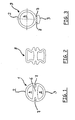
- Figure 1 shows a contact element 1, which consists of an elastically deformable material consists.
- This material is either continuously conductive (for example by Admixture of conductive particles in the base material) or such with a electrically conductive layer (not shown here) provided over this Contact element 1, the contact between a first contact partner and at least one other contact partner can be done.
- the contact element 1 With its contact surfaces 2, 3 in Investment.
- the contact element 1 two recesses, 4, 5, which are designed so that in between a web 6 is located at least partially, in particular a circumferential Constriction 7 includes. Due to this shape, especially with the Constriction 7, and the elastic deformability, the contact element. 1 in a multi-component process in a recess of a housing or a carrier can be used.
- FIG. 2 shows a further geometric embodiment of a contact element 8, which is similar to the contact element 1 according to Figure 1, but substantially in has approximately rectangular or square cross-section.
- FIG. 3 shows a contact element 9, which likewise has a constriction 7.
- the contact element 9 is shaped so that it is in the direction of Contact surface 2 again has the recess 4, but not in the direction of Contact surface 3.
- Such a shape is preferably used when in Direction of the contact surface 2 larger tolerances, but in the direction of Contact surface 2 only slight tolerances must be compensated.
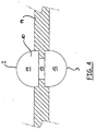
- FIG. 4 shows a contact element 10 designed as a solid profile (made of solid material) is.
- Two similar (or different from each other) contact bodies 11, 12, which are designed, for example dome-shaped, in turn, consist of a elastically deformable material and are electrically conductive, so that a Connection between the two contact surfaces 2, 3 is given, with which the Contact element 10 at the corresponding contact partners for conditioning can come.
- FIG. 1 shows a contact element 10 designed as a solid profile (made of solid material) is.
- the contact element 10 is again shaped in such a way that that between the two contact bodies 11, 12 at least partially, in particular circumferentially a constriction (referred to here as bridge 13) is formed with the the contact element 10 in a corresponding recess of one shown here Housing 14 can be used, but it is also conceivable that there is no constriction between the two contact bodies.
- Figure 5 shows the further embodiment of a contact element 15, which in corresponds approximately to the shape and function of the contact element 1 according to FIG. 1, wherein the contact element 15 has approximately the shape of an "8", so that the Recesses 4, 5 are approximately circular. But also other geometric ones Forms of the outer or inner contour (for example, square or rectangular Shapes, trapezoidal shapes, triangular shapes) or combinations thereof conceivable.
- Figure 6 shows the further embodiment of a contact element 16, not more a constriction for attachment of the contact element in the housing 14 with a recess 17, but at least partially, in particular completely circumferential collar 18 (or alternatively one or several collar sections).
- the contact element 16, in turn Contact surfaces 2, 3, is in the at least one recess 17 of the Housing 14 is inserted and over the collar 18 on or in the housing 14th established. This can be done for example by gluing, if the Contact element 16 after production of the housing 14 in the recess 17th is used.
- the contact element 16 in a Insert mold for the housing to be produced 14 and then the To manufacture housing (for example by a plastic injection molding process), so that after formation of the housing 14, the contact element 16 by material closure is fixed.
- FIG. 7 shows a further embodiment of an inventive device Contact element 19, which in the one direction two or more arms 20 and has a contact surface 3 in the other direction. It is also conceivable that the contact region of the contact element 19 is designed in the form of a shell. Likewise, this contact element 19 on the constriction 7 and is made of a made elastically deformable material which is electrically conductive, wherein the contact element 19 by means of its constriction 7 in the housing or a carrier 14, as already described in the preceding figures, is determinable.
- the right-hand illustration of FIG. 7 shows the contact element 19, after it has been introduced between two contact partners 21 and 22. These contact partners 21 and 22 are once at a preferred Application around the contact point of an antenna structure, eg. B.
Landscapes
- Details Of Aerials (AREA)
Applications Claiming Priority (4)
| Application Number | Priority Date | Filing Date | Title |
|---|---|---|---|
| DE102004013520 | 2004-03-19 | ||
| DE102004013520 | 2004-03-19 | ||
| DE102004042709A DE102004042709A1 (de) | 2004-03-19 | 2004-09-03 | Vorrichtung zur Kontaktierung einer Antennenstruktur, hergestellt in einem Mehrkomponentenverfahren |
| DE102004042709 | 2004-09-03 |
Publications (2)
| Publication Number | Publication Date |
|---|---|
| EP1577974A2 true EP1577974A2 (fr) | 2005-09-21 |
| EP1577974A3 EP1577974A3 (fr) | 2006-01-18 |
Family
ID=34839609
Family Applications (1)
| Application Number | Title | Priority Date | Filing Date |
|---|---|---|---|
| EP05001541A Withdrawn EP1577974A3 (fr) | 2004-03-19 | 2005-01-26 | Dispositif pour contacter une structure d 'antenne, produite par moulage par injection à plusieurs composants |
Country Status (2)
| Country | Link |
|---|---|
| EP (1) | EP1577974A3 (fr) |
| DE (1) | DE102004042709A1 (fr) |
Families Citing this family (1)
| Publication number | Priority date | Publication date | Assignee | Title |
|---|---|---|---|---|
| DE102008004103A1 (de) | 2007-01-11 | 2008-07-31 | Hirschmann Car Communication Gmbh | Vorrichtung zur Kontaktierung einer Antennenstruktur mit einem Kontaktelement mit einseitig offenem Profil |
Family Cites Families (6)
| Publication number | Priority date | Publication date | Assignee | Title |
|---|---|---|---|---|
| US4050756A (en) * | 1975-12-22 | 1977-09-27 | International Telephone And Telegraph Corporation | Conductive elastomer connector and method of making same |
| DE19823202C2 (de) * | 1998-05-25 | 2003-05-28 | Hirschmann Electronics Gmbh | Fahrzeug-Antenneneinrichtung |
| US6348659B1 (en) * | 1999-01-07 | 2002-02-19 | Thomas & Betts International, Inc. | Resilient electrical interconnects having non-uniform cross-section |
| EP1061608A3 (fr) * | 1999-05-10 | 2002-10-02 | Hirose Electric Co., Ltd. | Connecteurs électriques entre deux plaquettes à circuits imprimés |
| US20030074780A1 (en) * | 2001-05-16 | 2003-04-24 | Ericsson Inc. | Three-dimensional elastomeric connector |
| DE20321550U1 (de) * | 2003-08-11 | 2007-12-20 | Hirschmann Electronics Gmbh & Co. Kg | Elastische Kontaktelemente zum Einclipsen |
-
2004
- 2004-09-03 DE DE102004042709A patent/DE102004042709A1/de not_active Withdrawn
-
2005
- 2005-01-26 EP EP05001541A patent/EP1577974A3/fr not_active Withdrawn
Also Published As
| Publication number | Publication date |
|---|---|
| EP1577974A3 (fr) | 2006-01-18 |
| DE102004042709A1 (de) | 2005-10-13 |
Similar Documents
| Publication | Publication Date | Title |
|---|---|---|
| EP0840673B1 (fr) | Element de fixation | |
| WO2020007555A1 (fr) | Élément de liaison à enfichage pour un véhicule à moteur et procédé pour la fabrication d'un tel élément de liaison à enfichage | |
| LU92994B1 (de) | Tragschienenbaugruppe mit einem Bussystem und einem eine Leiterplatte aufweisenden Elektronikgerät | |
| DE202004021354U1 (de) | Elastische Kontaktelemente | |
| DE102016200243A1 (de) | Kontaktverbinder, Anschlusskontakt und Verfahren zur Herstellung eines Kontaktverbinders | |
| WO2017093517A1 (fr) | Antenne de toit présentant une mise en contact directe entre un film d'antenne et une carte de circuits imprimés | |
| EP2201643B1 (fr) | Procédé de production d'un système d'antenne de véhicule | |
| EP1577974A2 (fr) | Dispositif pour contacter une structure d 'antenne, produite par moulage par injection à plusieurs composants | |
| WO2018006894A1 (fr) | Procédé de fabrication d'un substrat de composant électronique pour des applications automobiles | |
| EP1213186A2 (fr) | Dispositif de fixation de deux pièces entre-elles | |
| EP1507310A1 (fr) | Connecteur élastique avec verrouillage | |
| DE102012105352A1 (de) | Positionierelement | |
| EP4000140B1 (fr) | Module de connecteur enfichable pouvant être modularisé destiné à un connecteur enfichable industriel lourd | |
| DE10358120A1 (de) | Elastische Kontaktelemente zum Einclipsen | |
| EP1507309A1 (fr) | Connecteur avec verrouillage | |
| DE102012108859B4 (de) | Elektronikmodul | |
| DE19703841C2 (de) | Vorrichtung zum Zentrieren zweier Bauteile in Kraftfahrzeugen | |
| DE10316384A1 (de) | Kontaktadapter für die Kontaktierung einer Antennenstruktur eines Fahrzeuges | |
| DE10231715A1 (de) | Symmetrischer Steckverbinder | |
| DE102018106797A1 (de) | Komponententräger für im Wesentlichen elektrische/elektronische Bauelemente als Bestandteil von Kraftfahrzeugschließsystemen | |
| DE102009048527B4 (de) | Anordnung von mehreren Schaltungsträgern und Verfahren zur Herstellung einer derartigen Anordnung | |
| WO2018149543A1 (fr) | Dispositif pour assurer le montage d'un composant à son emplacement d'installation prévu | |
| DE102017221543A1 (de) | Leiterplattennutzen | |
| EP1507308A2 (fr) | Eléments de contact du type à levier | |
| DE102023132202A1 (de) | Befestigung von Steuergeräten |
Legal Events
| Date | Code | Title | Description |
|---|---|---|---|
| PUAI | Public reference made under article 153(3) epc to a published international application that has entered the european phase |
Free format text: ORIGINAL CODE: 0009012 |
|
| AK | Designated contracting states |
Kind code of ref document: A2 Designated state(s): AT BE BG CH CY CZ DE DK EE ES FI FR GB GR HU IE IS IT LI LT LU MC NL PL PT RO SE SI SK TR |
|
| AX | Request for extension of the european patent |
Extension state: AL BA HR LV MK YU |
|
| PUAL | Search report despatched |
Free format text: ORIGINAL CODE: 0009013 |
|
| AK | Designated contracting states |
Kind code of ref document: A3 Designated state(s): AT BE BG CH CY CZ DE DK EE ES FI FR GB GR HU IE IS IT LI LT LU MC NL PL PT RO SE SI SK TR |
|
| AX | Request for extension of the european patent |
Extension state: AL BA HR LV MK YU |
|
| RIC1 | Information provided on ipc code assigned before grant |
Ipc: H01R 13/24 20060101ALI20051201BHEP Ipc: H01Q 1/32 20060101ALI20051201BHEP Ipc: H01Q 1/12 20060101AFI20050526BHEP |
|
| 17P | Request for examination filed |
Effective date: 20060211 |
|
| AKX | Designation fees paid |
Designated state(s): AT BE BG CH CY CZ DE DK EE ES FI FR GB GR HU IE IS IT LI LT LU MC NL PL PT RO SE SI SK TR |
|
| 17Q | First examination report despatched |
Effective date: 20081127 |
|
| STAA | Information on the status of an ep patent application or granted ep patent |
Free format text: STATUS: THE APPLICATION IS DEEMED TO BE WITHDRAWN |
|
| 18D | Application deemed to be withdrawn |
Effective date: 20080801 |