EP1579996A2 - Tintenstrahldrucker und Tintenstrahldruckverfahren - Google Patents
Tintenstrahldrucker und Tintenstrahldruckverfahren Download PDFInfo
- Publication number
- EP1579996A2 EP1579996A2 EP05013612A EP05013612A EP1579996A2 EP 1579996 A2 EP1579996 A2 EP 1579996A2 EP 05013612 A EP05013612 A EP 05013612A EP 05013612 A EP05013612 A EP 05013612A EP 1579996 A2 EP1579996 A2 EP 1579996A2
- Authority
- EP
- European Patent Office
- Prior art keywords
- ink
- voltage
- pressure generation
- generation chamber
- signal
- Prior art date
- Legal status (The legal status is an assumption and is not a legal conclusion. Google has not performed a legal analysis and makes no representation as to the accuracy of the status listed.)
- Withdrawn
Links
Images


Classifications
-
- B—PERFORMING OPERATIONS; TRANSPORTING
- B41—PRINTING; LINING MACHINES; TYPEWRITERS; STAMPS
- B41J—TYPEWRITERS; SELECTIVE PRINTING MECHANISMS, i.e. MECHANISMS PRINTING OTHERWISE THAN FROM A FORME; CORRECTION OF TYPOGRAPHICAL ERRORS
- B41J2/00—Typewriters or selective printing mechanisms characterised by the printing or marking process for which they are designed
- B41J2/005—Typewriters or selective printing mechanisms characterised by the printing or marking process for which they are designed characterised by bringing liquid or particles selectively into contact with a printing material
- B41J2/01—Ink jet
- B41J2/015—Ink jet characterised by the jet generation process
- B41J2/04—Ink jet characterised by the jet generation process generating single droplets or particles on demand
- B41J2/045—Ink jet characterised by the jet generation process generating single droplets or particles on demand by pressure, e.g. electromechanical transducers
- B41J2/04501—Control methods or devices therefor, e.g. driver circuits, control circuits
- B41J2/04541—Specific driving circuit
-
- B—PERFORMING OPERATIONS; TRANSPORTING
- B41—PRINTING; LINING MACHINES; TYPEWRITERS; STAMPS
- B41J—TYPEWRITERS; SELECTIVE PRINTING MECHANISMS, i.e. MECHANISMS PRINTING OTHERWISE THAN FROM A FORME; CORRECTION OF TYPOGRAPHICAL ERRORS
- B41J2/00—Typewriters or selective printing mechanisms characterised by the printing or marking process for which they are designed
- B41J2/005—Typewriters or selective printing mechanisms characterised by the printing or marking process for which they are designed characterised by bringing liquid or particles selectively into contact with a printing material
- B41J2/01—Ink jet
- B41J2/015—Ink jet characterised by the jet generation process
- B41J2/04—Ink jet characterised by the jet generation process generating single droplets or particles on demand
- B41J2/045—Ink jet characterised by the jet generation process generating single droplets or particles on demand by pressure, e.g. electromechanical transducers
- B41J2/04501—Control methods or devices therefor, e.g. driver circuits, control circuits
- B41J2/04581—Control methods or devices therefor, e.g. driver circuits, control circuits controlling heads based on piezoelectric elements
-
- B—PERFORMING OPERATIONS; TRANSPORTING
- B41—PRINTING; LINING MACHINES; TYPEWRITERS; STAMPS
- B41J—TYPEWRITERS; SELECTIVE PRINTING MECHANISMS, i.e. MECHANISMS PRINTING OTHERWISE THAN FROM A FORME; CORRECTION OF TYPOGRAPHICAL ERRORS
- B41J2/00—Typewriters or selective printing mechanisms characterised by the printing or marking process for which they are designed
- B41J2/005—Typewriters or selective printing mechanisms characterised by the printing or marking process for which they are designed characterised by bringing liquid or particles selectively into contact with a printing material
- B41J2/01—Ink jet
- B41J2/015—Ink jet characterised by the jet generation process
- B41J2/04—Ink jet characterised by the jet generation process generating single droplets or particles on demand
- B41J2/045—Ink jet characterised by the jet generation process generating single droplets or particles on demand by pressure, e.g. electromechanical transducers
- B41J2/04501—Control methods or devices therefor, e.g. driver circuits, control circuits
- B41J2/04588—Control methods or devices therefor, e.g. driver circuits, control circuits using a specific waveform
-
- B—PERFORMING OPERATIONS; TRANSPORTING
- B41—PRINTING; LINING MACHINES; TYPEWRITERS; STAMPS
- B41J—TYPEWRITERS; SELECTIVE PRINTING MECHANISMS, i.e. MECHANISMS PRINTING OTHERWISE THAN FROM A FORME; CORRECTION OF TYPOGRAPHICAL ERRORS
- B41J2/00—Typewriters or selective printing mechanisms characterised by the printing or marking process for which they are designed
- B41J2/005—Typewriters or selective printing mechanisms characterised by the printing or marking process for which they are designed characterised by bringing liquid or particles selectively into contact with a printing material
- B41J2/01—Ink jet
- B41J2/015—Ink jet characterised by the jet generation process
- B41J2/04—Ink jet characterised by the jet generation process generating single droplets or particles on demand
- B41J2/045—Ink jet characterised by the jet generation process generating single droplets or particles on demand by pressure, e.g. electromechanical transducers
- B41J2/04501—Control methods or devices therefor, e.g. driver circuits, control circuits
- B41J2/04593—Dot-size modulation by changing the size of the drop
Definitions
- the present invention relates to an ink jet printer and an ink jet type for printing by ink discharged from a nozzle by expanding and shrinking a pressure generation chamber filled with the ink by an electro-mechanic converter consisting of a piezoelectric element or the like.
- the present invention relates to an ink jet printer and an ink jet printing method in which the pressure chamber is expanded in a stepped manner so as to discharge fine ink droplets at a high speed, thus improving the image quality, and the pressure chamber is contracted prior to ink discharge so that a wide range of ink droplet size is discharged, realizing, a highly accurate gradation printing.
- the present invention also improve the service life of the electro-mechanic converter such as a piezoelectric element.
- the ink jet printer has been used as a printing apparatus for recording on a recording paper a data from an electronic processing apparatus such as a computer.
- the ink jet printer uses a piezoelectric element or other electro-mechanic converter to expand and contract a pressure generation chamber filled with ink so as to discharge the ink from a nozzle communicating with the pressure generation chamber for printing on a recording paper. Since the ink jet printer can be manufactured with a simple configuration of a small size at reasonable costs, it is widely used for business and private use at home.
- a printer In general, a printer is required to have a high quality and high speed printing capability. Especially with the recent spread of personal computers, a high speed and high density recording is strongly desired.
- the ink droplet size For performing a high-density recording in the ink jet printer, it is necessary to reduce the ink droplet size, for example, by reducing the diameter of the nozzle.
- a nozzle of a small diameter has difficulty in production as well as has a problem of clogging, deteriorating the reliability. Accordingly, reduction in the nozzle diameter has a limitation.
- a drive voltage signal is applied to deform the piezoelectric element.
- the drive voltage signal which has been used is a trapezoidal wave as shown in Fig. 14.
- a drive voltage V1 is increased for time T1 and applied for time T2. This deforms the piezoelectric element to push the wall of the pressure generation chamber.
- the pressure generation chamber is contracted to discharge the ink filled inside.
- the piezoelectric element When the drive current is decreased to V0, the piezoelectric element returns to its previous form and the pressure generation chamber returns to its previous volume, so that ink is filled from a common ink tank communicating with the pressure generation chamber.
- This contraction and expansion of the pressure generation chamber are repeated to discharge ink for printing a predetermined image or character on a printing paper.
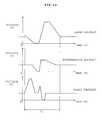
- Fig. 15 show as regions “a” to “f” as the maximum values of the ink droplet speed which can be obtained constantly when driven by various drive methods in the ink jet printer including the conventional technique and present invention which will be detailed later.
- Japanese Patent Publication A55-17589 [1] discloses a Pull-Push Method (so-called "hikiuchi” in Japanese), i.e., starting an ink discharge at the moment when the ink meniscus is pulled into the nozzle.
- Fig. 16 shows a waveform of the drive signal of this pull-push drive method. Prior to contract the pressure generation chamber to discharge an ink droplet, the pressure generation chamber is once expanded. This brings about two merits.
- Japanese Patent Publication A59-133067 [2] suggests a drive method for applying a voltage signal so as to pull back the ink into the nozzle before the ink droplet discharge is complete.
- the drive signal is triangular, where the voltage application maintaining time T2 in the conventional drive signal is made zero, so that the ink column during ink discharge is broken earlier.
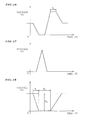
- Japanese Patent Publication B4-36071 [3] suggests a drive method of rapid meniscus pulling and maintaining the state to discharge a very small droplet.
- the drive signal has a reversed trapezoidal waveform, wherein the contraction time T4 of the pressure generation chamber is reduced and the bias voltage V2 is increased, so that a protrusion is formed at the center of the meniscus during a contraction maintaining time T5 of the pressure generation chamber.
- This protrusion is broken off from the meniscus and becomes an ink droplet.
- the aforementioned ink jet printers have a problem that it is impossible to obtain both of the ink droplet size reduction and an appropriate ink droplet speed.
- the ink column at the initial stage of the ink discharge is formed by the same phenomenon of the drive method of Fig. 14. Accordingly, like in the case of simple trapezoidal wave, it is impossible to make the head of the ink column smaller than the nozzle diameter. Thus, it is impossible to discharge an ink droplet smaller than the nozzle diameter.
- the aforementioned drive methods of the ink jet printer can reduce the ink droplet size but this is accompanied by reduction in the ink droplet speed. As a result, it has been difficult to realize clear printing at a high speed with a very small ink droplet.
- the ink jet printer comprises: a nozzle for discharging ink; a pressure generation chamber communicating with the nozzle; a common ink tank for supplying ink to the pressure generation chamber; an electro-mechanic converter connected to at least one wall of the pressure generation chamber; and a control unit for applying a drive voltage signal to the electro-mechanic converter; the electro-mechanic converter being deformed by a drive voltage signal from the control unit, so as to expand or contract the pressure generation chamber to discharge ink from the nozzle, and wherein the control unit generates: a first expansion signal which deforms the electro-mechanic converter so as to expand the pressure generation chamber and maintain the expanded state for a predetermined period of time, so that ink is discharged from the nozzle; and a second expansion signal, following the first expansion signal, which deforms the electro-mechanic converter so as to further expand the pressure generation chamber, so that an ink column discharged from the nozzle is broken off at an early stage and an unnecessary portion of the ink is pulled back into the
- the control unit In the ink jet printer having the aforementioned configuration, the control unit generates a first expansion signal so as to expand the pressure generation chamber via an electro-mechanic converter such as a piezoelectric element and the expanded state is maintained, so that the ink meniscus is abruptly retrieved and vibrated so as to discharge the ink; and generates a second expansion signal so as to further expand the pressure generation chamber, so that an ink column is broken off and an unnecessary portion of the ink is pulled back into the nozzle.
- an electro-mechanic converter such as a piezoelectric element
- the present invention enables to discharge an ink droplet having a diameter smaller than the nozzle diameter.
- the present invention enables to obtain a smaller droplet at a higher speed, thus improving the printing quality.
- the present invention expands the pressure generation chamber in a stepped manner to realize ink droplet discharge and break-off at an early state.
- the present invention enables to discharge a smaller ink droplet.
- control unit generates: a first contraction signal to deform the electro-mechanic converter so as to contract the pressure generation chamber without discharging ink from the nozzle; and a first expansion signal to deform the electro-mechanic converter so as to expand the pressure generation chamber and maintain the expanded state for a predetermined period of time, so that ink is discharged from the nozzle.
- the control unit generates: a first contraction signal to deform the electro-mechanic converter so as to contract the pressure generation chamber without discharging ink from the nozzle; a first expansion signal to deform the electro-mechanic converter so as to expand the pressure generation chamber and maintain the expanded state for a predetermined period of time, so that ink is discharged from the nozzle; and a second expansion signal, following the first expansion signal, so as to deform the electro-mechanic converter to further expand the pressure generation chamber, so that an ink column discharged from the nozzle is broken off at an early stage and an unnecessary portion of the ink is pulled back into the nozzle.
- control unit before generating the first expansion signal to discharge ink, generates the first contraction signal for contracting the pressure generation changer to a degree not to discharge ink.
- bias voltage applied in advance to the piezoelectric element is normally set at a high value and the drive waveform also has a high voltage.
- the bias voltage should be decreased to a reference voltage for discharging a large droplet. This requires a long period of time before the discharge timing. On the contrary, when discharging a small droplet, after the discharge, the voltage should increased to the bias voltage and a long period of time is required after the discharge timing.
- one ink discharge cycle requires a long period of time, which disables a high speed printing.
- the first contraction signal is generated to contract the pressure generation chamber to a degree not to discharge ink. This enables to obtain a large, intermediate, and small droplets at a high speed with a bias voltage and a drive voltage lower than in the conventional apparatus.
- the present invention When the present invention is driven without lowering the bias voltage, it is possible to set a large droplet at a value larger and a small droplet at a value smaller than in the conventional apparatus. This improves the gradation width, enabling printing with a higher accuracy.
- the bias voltage can be set at a low value, it is possible to set one discharge cycle than the aforementioned case, thus enabling to significantly improve the repetition drive frequency.
- the present invention with a lower voltage than the conventional drive voltage, it is possible to drive the piezoelectric element within a shorter time. That is, it is possible to obtain a wider gradation drive at a high speed, enabling to perform a high-speed and a high-accuracy printing. Since the drive voltage can be low, it is also possible to improve the service life of the piezoelectric life.
- control unit may generate a second contraction signal between the first expansion signal and the second expansion signal, so as to deform the electro-mechanic converter to temporarily contract the pressure generation chamber, thus increasing speed of the ink droplet discharge from the nozzle.
- control unit In the ink jet printer having the aforementioned configuration, the control unit generates the second contraction signal after the first expansion signal, so as to temporarily contract the pressure generating chamber.
- the second contraction signal may be followed by the second expansion signal immediate after, or after maintaining for a certain time the pressure generation chamber in the contracted state.
- control unit may generate a third contraction signal following the second expansion signal, so as to deform the electro-mechanic converter to contract the pressure generation chamber, so that residual vibration of the ink meniscus in the nozzle is suppressed.
- control unit In the ink jet printer having the aforementioned configuration, the control unit generates the third contraction signal after the second expansion signal, so as to contract the pressure generating chamber.
- the residual vibration of the meniscus after an ink droplet discharge can be suppressed at an early stage and accordingly, it is possible to perform drive with a high repetition frequency, enabling to perform printing with a smaller droplet at a high speed and a high resolution.
- the printing quality is significantly improved.
- the ink jet printing method uses an ink jet printer comprising a nozzle for discharging ink; a pressure generation chamber communicating with the nozzle; a common ink tank for supplying ink to the pressure generation chamber; an electro-mechanic converter connected to at least one wall of the pressure generation chamber; and a control unit for applying a drive voltage signal to the electro-mechanic converter; the electro-mechanic converter being deformed by a drive voltage signal from the control unit, so as to expand or contract the pressure generation chamber, so that ink is discharged from the nozzle, the method comprising: a first expansion step in which the electro-mechanic converter is deformed by a signal from the control unit to expand the pressure generation chamber and maintain the expanded state for a predetermined period of time, so that ink is discharged from the nozzle; and a second expansion step following the first expansion step, wherein the electro-mechanic converter is deformed by a signal from the control unit to further expand the pressure generation chamber, so as to break off an ink column to be
- the method may comprise: a first contraction step in which the electro-mechanic converter is deformed by a signal from the control unit to contract the pressure generation chamber without discharging any ink from the nozzle, and a first expansion step following the first contraction step, wherein the electro-mechanic converter is deformed by a signal from the control unit to expand the pressure generation chamber and maintain the expanded state for a predetermined period of time, so as to discharge ink from the nozzle.
- the method may comprise: a first contraction step in which the electro-mechanic converter is deformed by a signal from the control unit to contract the pressure generation chamber without discharging any ink from the nozzle; a first expansion step following the first contraction step, wherein the electro-mechanic converter is deformed by a signal from the control unit to expand the pressure generation chamber and maintain the expanded state for a predetermined period of time, so as to discharge ink from the nozzle; and a second expansion step following the first expansion step, wherein the electro-mechanic converter is deformed by a signal from the control unit to further expand the pressure generation chamber, so as to break off the ink column to be discharged from the nozzle at an early stage and pull an unnecessary portion of the ink back into the nozzle.
- the method may further comprise a second contraction step between the first expansion step and the second expansion step, wherein the electro-mechanic converter is deformed to temporarily contract the pressure generation chamber so as to increase speed of an ink droplet to be discharged from the nozzle.
- the method may further comprise a third contraction step following the second expansion step, wherein the electro-mechanic converter is deformed by a signal from the control unit to contract the pressure generation chamber so as to suppress residual vibration of the ink meniscus in the nozzle.
- Fig. 1 is a cross sectional view of an essential portion of a printing head of the ink jet printer of the present invention.
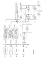
- Fig. 2 is a block diagram showing a control unit of the ink jet printer according to a first embodiment.
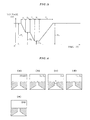
- Fig. 3 is a graph showing a drive waveform of the ink jet printer according to the first embodiment.
- Fig. 4 explains an ink meniscus of the ink jet printer according to the first embodiment.
- Fig. 15 as has been described above, explains the ink droplet size and ink droplet speed obtained in ink jet printers.
- the ink jet printer includes: a nozzle 12 for discharging ink; a pressure generation chamber 11 communicating with this nozzle 12; and a common ink tank 14 for supplying ink via an ink supply passage 13 to the pressure generation chamber 11.
- the common ink tank 14, the pressure generation chamber 11, and the nozzle 12 are filled with ink.
- the pressure generation chamber 11 has a wall constituted by a diaphragm 16, which is connected to a piezoelectric actuator (piezoelectric element) 15 serving as an electro-mechanic converter for the diaphragm 16.
- nozzles 12 and pressure generation chambers 11 there are a plurality of nozzles 12 and pressure generation chambers 11, each of which is provided with a diaphragm 16 and a piezoelectric actuator 15.
- the piezoelectric actuator 15 is connected to a control unit 20, so that a drive voltage signal is applied from the control unit.
- Fig. 2 is a block diagram of the control unit 20 of the present embodiment.
- control unit 20 includes: a CPU 21 for controlling components of the control unit 20; a ROM 22 containing a routine or the like for various data processing; a RAM 23 for storing various data items; an interface 24 for receiving a printing data from a computer (not depicted); and drive waveform generation circuit 25 (25a, 25b, 25c) for generating a drive waveform signal to the piezoelectric actuator 15.
- a CPU 21 for controlling components of the control unit 20
- ROM 22 containing a routine or the like for various data processing
- RAM 23 for storing various data items
- an interface 24 for receiving a printing data from a computer (not depicted)
- drive waveform generation circuit 25 25a, 25b, 25c for generating a drive waveform signal to the piezoelectric actuator 15.
- the drive waveform generation circuit 25 includes a large droplet drive waveform generation circuit 25a, an intermediate droplet drive waveform generation circuit 25b, and a small droplet drive waveform generation circuit 25c for performing gradation printing which will be detailed later.
- Drive waveform signals from these drive waveform generation circuits 25a, 25b, and 25c are output via a switch circuit 28 to the piezoelectric actuator 15.
- a plurality of piezoelectric actuators 15-1, 15-2, ... 15-n are arranged corresponding to a plurality of nozzles (not depicted).
- the switch circuit 28 for outputting a signal to the plurality of piezoelectric actuators includes three switch circuits 28-1a, 28-1b, 28-1c, 28-2a, 28-2b, 28-2c,... 28-na, 28-nb, 28-nc corresponding to the three drive waveform generation circuits 25a, 25b, and 25c for each of the piezoelectric actuators 15-1, 15-2, and 15-n.
- control unit 20 includes a data transmission circuit 26 and a data reception circuit 27.
- the data transmission circuit 26 converts a parallel printing data supplied via the bus 20a from the interface 24 and the CPU 21, into a serial printing data and transmits the converted data to the data reception circuit 27.
- the data reception circuit 27 decodes the serial printing data from the data transmission circuit 26, so as to control the switch circuits 28.
- each of the piezoelectric actuators 15 is deformed to push or release the diaphragm 16 to expand or contract the pressure generation chamber 11, so that an ink droplet 17 is discharged from the nozzle 12.
- the aforementioned drive signal as shown in Fig. 14 is applied to the piezoelectric actuator 15, so that the piezoelectric actuator 15 pushes the diaphragm 16 so as to contract the pressure generation chamber 11 to discharge an ink droplet 17 from the nozzle 12.
- the drive signal is modified according to the size of the ink droplet to be discharged.
- the pressure generation chamber 11 is expanded by a drive signal from the control unit and the expanded state is maintained while the ink droplet 17 is discharged from the nozzle 12.
- control unit 20 of the present embodiment generates a first expansion signal for discharging the ink from the nozzle 12 by deforming the piezoelectric actuator 15 to expand the pressure generation chamber 11 and maintaining the expanded state for a predetermined period of time; and a second expansion signal to further deform the piezoelectric actuator 15 to further expand the pressure generation chamber 11 from the first expanded state, so that an ink column discharging the nozzle 12 is broken earlier so as to be discharged from the nozzle 12 and simultaneously with this an unnecessary portion of the ink is pulled back into the nozzle 12.
- Fig. 3 shows a drive waveform applied to the piezoelectric actuator 15 from the control unit 20 according to the present embodiment.
- Voltage V1 and V4 are bias voltage applied during a repeated discharge or prior to discharge.
- Voltage V2 is a first expansion signal for expanding the pressure generation chamber abruptly enough to discharge an ink droplet from the nozzle 12 and maintaining the expansion.
- the voltage V1 is dropped to voltage V2 for a period of time T1, and this state is maintained for a period of time T2.
- This voltage V2 is applied for time T1 and T2, which vibrates the ink meniscus.
- time T1 and T2 are determined by a natural period of an ink jet head flow system.
- the voltage V2 is followed by voltage V3 which is a second expansion signal for abruptly expanding and maintaining the pressure generation chamber for pulling back an unnecessary portion of ink into the nozzle 12.
- the voltage V2 is dropped to voltage V3 for a time T3.
- This voltage V3 is applied for time T3, which promotes early destruction of the ink column during the ink discharge, enabling to discharge a further smaller droplet.
- voltage V4 After an ink droplet is discharged, voltage V4 returns the system to a state prior to printing operation start. The state of voltage V3 is maintained for time T4, the voltage is increased to the bias voltage V4 for time T5.
- the signal waveform thus explained constitutes a cycle.
- ink is discharged from the nozzle 12 and a character or image is recorded on a printing paper (not depicted).
- control unit 20 applies the bias voltage V1 to the piezoelectric actuator 15.
- control unit 20 generates the first expansion signal, and in the piezoelectric actuator 15, the voltage V1 is decreased to voltage V2 for time T1 and the V2 is maintained for time T2.
- This first expansion signal is followed by the second expansion signal, and in the piezoelectric actuator 15, the voltage V2 is decreased to voltage V3 for time T3.
- the voltage V3 is maintained for time T4, the voltage is increased to the bias voltage V4, taking time T5.
- the aforementioned waveform constitutes one drive cycle to be repeated and the ink is discharged from the nozzle 12 and printing is performed on a sheet of paper.
- the voltage V4 is set identical to the voltage V4, i.e., the state prior to the generation of the first expansion signal.
- the drive cycle can be repeated smoothly.
- the control unit 20 generates the first expansion signal to expand the pressure generation chamber 11 via the piezoelectric actuator 15, which abruptly retrieves the ink meniscus and vibrates the ink meniscus to discharge an ink droplet; and the second expansion signal following immediately after the first expansion signal, so as to further expand the pressure generation chamber 11 to break off the ink column and retrieve an unnecessary portion of the ink back into the nozzle.
- the pressure generation chamber 11 is expanded by two steps, enabling to realize an early break off of the ink droplet. This enables to obtain a further smaller droplet than in the apparatus disclosed in Citation [3] in which the pressure generation chamber is expanded by a single step.
- the drive waveform of the present embodiment is more advantageous than the conventional drive waveform for obtaining a small droplet.
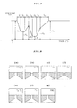
- Fig. 5 is a graph showing a drive waveform of the ink jet printer according to the second embodiment.
- Fig. 6 explains ink meniscus in the ink jet printer according to the second embodiment.
- a second contraction signal is generated between the first expansion signal and the second expansion signal, so as to deform the piezoelectric actuator to temporarily contract the pressure generation chamber 11, enabling to discharge an ink droplet from nozzle 12 at a high speed.
- the other drive method procedure is identical to the aforementioned first embodiment.
- Voltage V1 and V5 are bias voltages during a repeated discharge or prior to discharge.
- the waveform shown in Fig. 5 constitutes one cycle which is repeated smoothly.
- Voltage V2 is a first expansion signal to expand the pressure generation chamber abruptly enough to discharge an ink droplet from the nozzle 12. Voltage V1 decreased to V2 for a time T1 and the state is maintained for time T2.
- the voltage V2 is applied for time T1 and T2, and the ink meniscus is agitated.
- T1 and T2 are determined by the natural frequency of the flow path of the ink jet head.
- the voltage V2 is followed by voltage V3, which is a second contraction signal for temporarily contracting the pressure generation chamber.
- the voltage is increased from voltage V2 to voltage V3 for time T3.
- the time T3 is preferably set as short as possible. Considering the piezoelectric element reliability and the drive circuit electric problems, the time T3 is preferably set to several microseconds.
- the voltage V3 is followed by voltage V4, which is a second expansion signal to abruptly expand the pressure generation chamber to pull an unnecessary portion of ink back into the nozzle 12.
- the voltage V3 is decreased to voltage V4 for time T4.
- This voltage V4 is applied for time T4, which promotes early break off of the ink column during ink discharge, enabling to obtain a further smaller droplet.
- the time T4 to a short time so as not to involve a air bubble, and to set the voltage V4 smaller than V2: V2 > V4.
- Fig. 5 shows a case that the pressure chamber is contracted by the second contraction signal, and immediately after this, the second expansion signal is generated.
- the second expansion signal it is also possible to generate the second expansion signal after maintaining the contracted state of the pressure generation signal by the second contraction signal in a range that it is possible to obtain an effect to reduce the droplet size by the second expansion signal.
- the voltage V5 After an ink droplet is discharged, the voltage V5 returns the system to a state prior to printing operation start. After the state of voltage V4 is maintained for T5, the voltage is increased to bias voltage V5 for time T6.
- the aforementioned signal waveform constitutes one cycle, which is repeatedly driven and the ink is discharged from the nozzle 12 and an image or character is printed on a sheet of paper (not depicted).
- control unit 20 applies a bias voltage V1 to the piezoelectric actuator 15.
- control unit 20 generates a first expansion signal.
- voltage V1 is decreased to voltage V2 for time T1 and this state is maintained for time T2.
- the pressure generation chamber 11 is abruptly expanded so as to discharge an ink droplet from the nozzle 12, and this state is maintained. Accordingly, the ink meniscus is agitated as shown in Fig. 6B.
- This first expansion signal is followed by the second contraction signal.
- voltage V2 is increased to voltage V3 for time T3.
- This second contraction signal is followed by the second expansion signal, so that in the piezoelectric actuator, voltage V3 is decreased to voltage V4 for time T4.
- the voltage V4 state is maintained for time T5, and then the voltage is increased to bias voltage V5 for time T6.
- the meniscus vibration is gradually settled as shown in Fig. 6E returns to the state of Fig. 6F before a printing operation.
- the aforementioned signal waveform constitutes one cycle, which is repeatedly driven, and the ink is discharged from the nozzle 12 to print a character or image on a sheet of paper.
- the voltage V5 is set equal to the bias voltage V1. That is, the system returns to a state before generation of the first expansion signal. Accordingly, the drive is repeated smoothly.
- control unit 20 after the first expansion signal, generates the second contraction signal so as to temporarily contract the pressure generation chamber 11.
- the present embodiment enables to discharge a small ink droplet at a high speed, which in turn enables a printing of a high resolution, further improving the printing quality.
- Example 1 If this is compared to Example 1, the ink droplet speed can be increased twice or more. Thus, the present embodiment is more advantageous for obtaining a droplet speed than the drive waveform of Example 1.
- Fig. 7 is a graph showing a drive waveform of the ink jet printer according to the third embodiment of the present invention.
- Fig. 8 explains the ink meniscus in the ink jet printer of the third embodiment.
- control unit 20 after generating the second expansion signal, generates a third contraction signal so as to deform the piezoelectric actuator 15 to contract the pressure generation chamber 11, thus suppressing a residual vibration of the ink meniscus in the nozzle 12.
- the other portion of the printer components and the drive method is identical as in the first embodiment.
- Voltage V1 and V6 are a bias voltage preset beforehand or during a discharge.
- the waveform shown in Fig. 7 constitutes one cycle which is repeated smoothly.
- Voltage V2 is a first expansion signal to expand the pressure generation chamber abruptly enough to discharge an ink droplet from the nozzle 12. Voltage V1 decreased to V2 for a time T1 and the state is maintained for time T2.
- the voltage V2 is applied for time T1 and T2, and the ink meniscus is agitated.
- time T1 and T2 are determined by the natural frequency of the flow path of the ink jet head.
- Voltage V2 is followed by voltage V3, which is a second contraction signal for temporarily contracting and maintaining the pressure generation chamber for increasing the ink droplet discharge speed.
- the voltage V2 is increased to voltage V3 for a time T3.
- This voltage V3 is applied for time T3, which pushes the meniscus in the discharge direction, further increasing the ink droplet discharge speed.
- the time T3 is preferably as short as possible. Considering the piezoelectric reliability and electric problems of the drive circuit, the time T3 is preferably set in the order of several microseconds.
- Voltage V3 is followed by voltage V4, which is a second expansion signal for abruptly expanding the pressure generation chamber so as to pull back into the nozzle 12 an unnecessary portion of ink from the discharge ink droplet. Voltage V3 is decreased to voltage V4 for time T4.
- This voltage V4 applied for time T4 promotes early break off of the ink column during the ink discharge, enabling to discharge a further smaller droplet.
- the time T4 is preferably set small enough not to involve an air bubble. It is preferable that V2 > V4.
- the voltage V4 is followed by voltage V5, which is a third contraction signal for contracting the pressure generation chamber after the second expansion signal.
- the voltage V4 state is maintained for time T5 and the voltage is increased up to voltage V5 for time T6.
- This voltage V5 is applied for time T6, which suppresses residual vibration of the meniscus after a droplet discharge. Accordingly, it is possible to drive with a high repetition frequency.
- Time T6 and voltage V5 are preferably set as follows. The time T6 is set as small as possible within a range preventing the ink discharge from the nozzle 12 whereas the voltage V5 is set as large as possible. Thus, it is possible to obtain the maximum effect.
- Voltage V6 after discharge of an ink droplet is complete, returns the system to a state prior to printing operation start. The voltage is increased to V6 for time T7.
- the aforementioned signal waveform constitutes one cycle, which is repeatedly driven, so that ink is discharged from the nozzle 12 to print a character or image on a sheet of paper.
- control unit 20 applies a bias voltage V1 to the piezoelectric actuator 15.
- control unit 20 generates a first expansion signal.
- voltage V1 is decreased to voltage V2 for time T1 and this state is maintained for time T2.
- the pressure generation chamber 11 is abruptly expanded so as to discharge an ink droplet from the nozzle 12, and this state is maintained. Accordingly, the ink meniscus is agitated as shown in Fig. 8B.
- This first expansion signal is followed by the second contraction signal.
- voltage V2 is increased to voltage V3 for time T3.
- This second contraction signal is followed by the second expansion signal, so that in the piezoelectric actuator 15, voltage V3 is decreased to voltage V4 for time T4.
- This second expansion signal is followed by a third contraction signal.
- the voltage V4 state is maintained for time T5 and then increased to voltage V5 for time T6.
- the pressure generation chamber 11 suppresses the residual vibration of the meniscus after ink discharge.
- the aforementioned signal waveform constitutes one cycle, which is repeatedly driven, and the ink is discharged from the nozzle 12 to print a character or image on a sheet of paper.
- the voltage V6 is set equal to the bias voltage V1. That is, the system returns to a state before generation of the first expansion signal. Accordingly, the drive is repeated smoothly.
- control unit 20 after the second expansion signal, generates the third contraction signal so as to temporarily contract the pressure generation chamber 11.
- the present embodiment enables a printing of a high resolution, further improving the printing quality.
- Example 2 If this is compared to Example 2, repetition frequency can be almost doubled. Thus, the present embodiment is more advantageous for obtaining a small droplet with a higher repetition frequency than the drive waveform of Example 2.
- Fig. 9 is a graph showing a drive waveform of the ink jet printer according to the fourth embodiment of the present invention.
- Fig. 10 explains the ink meniscus in the ink jet printer of the fourth embodiment.
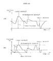
- Fig. 11 shows a drive waveform when performing a gradation printing using the ink jet printer of the present invention.
- Fig. 11A shows a case using other than the present embodiment, and
- Fig. 11B shows a case using the present embodiment.
- Fig. 12 and Fig. 13 are graphs showing a drive waveform when performing a gradation printing using the ink jet printer according to the present embodiment.
- Fig. 12 shows a case using embodiments other than the fourth embodiment, and fig. 13 shows a case using the fourth embodiment.
- control unit 20 prior to generating the first expansion signal, generates a first contraction signal so as to deform the piezoelectric actuator 15 to contract the pressure generation chamber 11.
- the other portion of the printer components and the drive method is identical as in the first embodiment.
- Voltage V1 and V6 are a bias voltage applied beforehand or during a discharge.
- the waveform shown in Fig. 9 constitutes one cycle which is repeated smoothly.
- Voltage V2 is a first contraction signal to contract the pressure generation chamber 11 in such a manner that no ink is discharged from the nozzle 12. Voltage V1 increased to V2 for a time T1 and this state is maintained for time T2.
- the voltage V3 is a first expansion signal for abruptly expanding the pressure generation chamber so as to discharge an ink droplet from the nozzle 12. Voltage is decreased from V2 to V3 for time T3 and this state is maintained for time T4.
- the voltage V3 is applied for time T3 and T4 so as to agitate the ink meniscus.
- time T3 and T4 are determined by the natural frequency of the flow path of the ink jet head.
- Voltage V3 is followed by voltage V4, which is a second contraction signal for temporarily contracting the pressure generation chamber for increasing the ink droplet discharge speed.
- the voltage is increased from V3 to voltage V4 for time T5.
- This voltage V4 is applied for time T3, which pushes the meniscus in the discharge direction, further increasing the ink droplet discharge speed.
- the time T5 is preferably as short as possible. Considering the piezoelectric reliability and electric problems of the drive circuit, the time T5 is preferably set in the order of several microseconds.
- Voltage V4 is followed by voltage V5, which is a second expansion signal for abruptly expanding the pressure generation chamber so as to pull back into the nozzle 12 an unnecessary portion of ink from the discharge ink droplet. Voltage is decreased from V4 to voltage V5 for time T6.
- This voltage V5 applied for time T6 promotes early break off of the ink column during the ink discharge, enabling to discharge a further smaller droplet.
- the time T6 is preferably set small enough not to involve an air bubble. It is preferable that V3 > V5.
- the voltage V5 is followed by voltage V6, which is a third contraction signal for contracting the pressure generation chamber 11 after the second expansion signal.
- the voltage V5 state is maintained for time T7 and the voltage is increased up to voltage V6 for time T8.
- This voltage V6 is applied for time T8, which suppresses residual vibration of the meniscus after a droplet discharge. Accordingly, it is possible to drive with a high repetition frequency.
- the aforementioned signal waveform constitutes one cycle, and this cycle is repeatedly driven, so that ink is discharged from the nozzle 12 for printing on a sheet of paper.
- Time T8 and voltage V6 are preferably set as follows. The time T8 is set as small as possible within a range preventing ink discharge, whereas the voltage V6 is set as large as possible. Thus, it is possible to obtain the maximum effect.
- control unit 20 applies a bias voltage V1 to the piezoelectric actuator 15.
- control unit 20 generates a first contraction signal.
- voltage V1 is increased to voltage V2 for time T1 and this state is maintained for time T2.
- the pressure generation chamber 11 is contracted in such a manner that no ink is discharged from the nozzle 12.
- This first contraction signal is followed by a first expansion signal.
- the voltage V2 is decreased to voltage V3 for time T3, and this state is maintained for time T4.
- the pressure generation chamber 11 is abruptly expanded, so that an ink droplet is discharged from the nozzle 12, and this state is maintained. This agitate the ink meniscus as shown in Fig. 10C.
- This first expansion signal is followed by the second contraction signal.
- voltage V3 is increased to voltage V4 for time T5.
- This second contraction signal is followed by the second expansion signal, so that in the piezoelectric actuator 15, voltage V4 is decreased to voltage V5 for time T3.
- This second expansion signal is followed by a third contraction signal.
- the voltage V5 state is maintained for time T7 and then increased to voltage V6 for time T8.
- the pressure generation chamber 11 suppresses the residual vibration of the meniscus after ink discharge.
- the meniscus vibration is settled as shown in Fig. 10G, and the system returns to the state before starting a printing operation.
- the aforementioned signal waveform constitutes one cycle, which is repeatedly driven, and the ink is discharged from the nozzle 12 to print a character or image on a sheet of paper.
- the voltage V6 is set equal to the bias voltage V1. That is, the system returns to a state before generation of the first expansion signal. Accordingly, the drive is repeated smoothly.
- control unit 20 before generating the first expansion signal for discharging ink, generates the first contraction signal so as to contract the pressure generation chamber 11 in such a manner that no ink is discharged and to maintain this state.
- Such a high bias voltage and drive voltage V1 increase the load on the piezoelectric actuator 15, leading to a short service life and disadvantage in the drive circuit cost.
- the first contraction signal is generated to contract the pressure generation chamber in such a manner that no ink is discharged and this state is maintained. Accordingly, as shown in Fig. 11B, it is possible to obtain a large, intermediate, and small droplets with a lower drive voltage V2 and a lower bias voltage than in the case of Fig. 11A.
- the reduction of the drive voltage and bias voltage reduces the load on the piezoelectric element and the drive circuit, and brings about advantage in costs.
- time required for one cycle of ink discharge is the time T3 shown in Fig. 12, disabling to perform a high-speed printing.
- the pressure generation chamber is contracted to a degree not discharging ink before ink discharge. Accordingly, one discharge cycle generating the first contraction signal can be set at T4 in Fig. 13, i.e., smaller than the case of Fig. 12.
- the ink jet printer and the ink jet printing method according to the present embodiment it is possible to drive the piezoelectric element in a shorter time than in the conventional printer and printing method.
- This enables to perform a wide gradation drive at a high speed. That is, it becomes possible to perform a high-speed, high-accuracy printing.
- drive can be performed with a low bias voltage, which improves the service life of the piezoelectric element.
- Example 3 If this is compared to Example 3, the same ink diameter, ink droplet speed, and repetition frequency can be obtained using a lower bias voltage: 10V in this example compared to 30V in Example 3.
- Example 4 shows that drive of a wide gradation width can be performed at a high speed, enabling a high-speed and highly-accurate printing.
- ink jet printer and the ink jet printing method according to the present invention is not to be limited to the aforementioned embodiments, but can be modified in various ways within the scope of the present invention.
- control unit 20 generates a first contraction signal prior to the first expansion signal and the second expansion signal, but the second expansion signal may also be omitted.
- the second contraction signal is generated to temporarily contract the pressure generation chamber and then the second expansion is generated.
- a drive signal for maintaining the piezoelectric element between the second contraction signal and the second expansion signal.
- the piezoelectric actuator is a piezoelectric element utilizing the longitudinal oscillation and longitudinal effect.
- the drive signal applied to the piezoelectric element may use waveform signals identical to the aforementioned embodiments as they are or reversed or offset in the voltage direction, which can be applied to the ink jet printer.
- the actuator for expanding and contracting the pressure generation chamber may be other than the piezoelectric element, if a vibrator can expand and contract according to a drive signal, such as a magnetostrictive element.
- the pressure generation chamber is expanded and contracted for ink discharge in a region where the volume of the pressure generation chamber is reduced in comparison to the stationary state.
- the pressure generation chamber is expanded in a stepped manner, enabling to discharge a very small ink droplet at a high speed, thus improving the image quality. Moreover, the pressure generation chamber is contracted before ink discharge, so that a wide range of ink droplet size can be discharged for gradation printing with a high accuracy, and the electromechanical converter such as a piezoelectric element can have a longer service life.
- the present invention enables to obtain an ink droplet smaller than the nozzle diameter discharged at a high speed and that with a high repetition frequency. This significantly improves printing quality.
Landscapes
- Particle Formation And Scattering Control In Inkjet Printers (AREA)
- Ink Jet (AREA)
Applications Claiming Priority (3)
| Application Number | Priority Date | Filing Date | Title |
|---|---|---|---|
| JP33477198 | 1998-11-25 | ||
| JP33477198A JP3223892B2 (ja) | 1998-11-25 | 1998-11-25 | インクジェット式記録装置及びインクジェット式記録方法 |
| EP99123426A EP1004441A3 (de) | 1998-11-25 | 1999-11-24 | Tintenstrahldrucker und Tintenstrahldruckverfahren |
Related Parent Applications (1)
| Application Number | Title | Priority Date | Filing Date |
|---|---|---|---|
| EP99123426A Division EP1004441A3 (de) | 1998-11-25 | 1999-11-24 | Tintenstrahldrucker und Tintenstrahldruckverfahren |
Publications (2)
| Publication Number | Publication Date |
|---|---|
| EP1579996A2 true EP1579996A2 (de) | 2005-09-28 |
| EP1579996A3 EP1579996A3 (de) | 2008-03-12 |
Family
ID=18281056
Family Applications (2)
| Application Number | Title | Priority Date | Filing Date |
|---|---|---|---|
| EP99123426A Withdrawn EP1004441A3 (de) | 1998-11-25 | 1999-11-24 | Tintenstrahldrucker und Tintenstrahldruckverfahren |
| EP05013612A Withdrawn EP1579996A3 (de) | 1998-11-25 | 1999-11-24 | Tintenstrahldrucker und Tintenstrahldruckverfahren |
Family Applications Before (1)
| Application Number | Title | Priority Date | Filing Date |
|---|---|---|---|
| EP99123426A Withdrawn EP1004441A3 (de) | 1998-11-25 | 1999-11-24 | Tintenstrahldrucker und Tintenstrahldruckverfahren |
Country Status (3)
| Country | Link |
|---|---|
| US (1) | US6312077B1 (de) |
| EP (2) | EP1004441A3 (de) |
| JP (1) | JP3223892B2 (de) |
Families Citing this family (33)
| Publication number | Priority date | Publication date | Assignee | Title |
|---|---|---|---|---|
| JP2001150672A (ja) * | 1999-01-29 | 2001-06-05 | Seiko Epson Corp | インクジェット式記録装置、及び、インクジェット式記録ヘッドの駆動方法 |
| JP3467570B2 (ja) * | 2000-08-04 | 2003-11-17 | セイコーエプソン株式会社 | 液体噴射装置、及び、液体噴射装置の駆動方法 |
| DE60204180T2 (de) * | 2001-03-09 | 2005-10-20 | Seiko Epson Corp. | Flüssigkeitsstrahlvorrichtung und Verfahren zu deren Steuerung |
| JPWO2003022582A1 (ja) | 2001-09-11 | 2004-12-24 | セイコーエプソン株式会社 | 液体吐出ヘッド駆動方法及び液体吐出装置 |
| US7249816B2 (en) * | 2001-09-20 | 2007-07-31 | Ricoh Company, Ltd. | Image recording apparatus and head driving control apparatus |
| JP4408608B2 (ja) * | 2002-06-24 | 2010-02-03 | 株式会社リコー | ヘッド駆動制御装置及び画像記録装置 |
| US6908167B2 (en) * | 2002-08-01 | 2005-06-21 | Konica Corporation | Ink-jet recording apparatus |
| US7073878B2 (en) * | 2002-09-30 | 2006-07-11 | Seiko Epson Corporation | Liquid ejecting apparatus and controlling unit of liquid ejecting apparatus |
| JP2005169963A (ja) | 2003-12-15 | 2005-06-30 | Canon Inc | 液体吐出方法およびその装置 |
| JP4492131B2 (ja) * | 2004-01-19 | 2010-06-30 | 富士ゼロックス株式会社 | 液滴吐出ヘッド駆動方法および液滴吐出装置 |
| US8491076B2 (en) | 2004-03-15 | 2013-07-23 | Fujifilm Dimatix, Inc. | Fluid droplet ejection devices and methods |
| US7281778B2 (en) * | 2004-03-15 | 2007-10-16 | Fujifilm Dimatix, Inc. | High frequency droplet ejection device and method |
| JP3956950B2 (ja) * | 2004-03-30 | 2007-08-08 | 富士フイルム株式会社 | 吐出ヘッド駆動方法及び吐出ヘッド製造方法並びに液吐出装置 |
| JP4678158B2 (ja) * | 2004-09-03 | 2011-04-27 | 富士ゼロックス株式会社 | 液滴吐出ヘッドの駆動方法、液滴吐出ヘッド、及び液滴吐出装置 |
| JP2006205720A (ja) * | 2004-12-28 | 2006-08-10 | Seiko Epson Corp | 液体吐出装置、液体吐出方法、および、プログラム |
| EP1836056B1 (de) | 2004-12-30 | 2018-11-07 | Fujifilm Dimatix, Inc. | Tintenstrahldruck |
| US8746827B2 (en) * | 2005-06-09 | 2014-06-10 | Xerox Corporation | Ink jet apparatus |
| US7549716B2 (en) * | 2005-07-01 | 2009-06-23 | Ricoh Printing Systems, Ltd. | Method of ejecting microdroplets of ink |
| JP5125004B2 (ja) * | 2005-07-01 | 2013-01-23 | リコープリンティングシステムズ株式会社 | 微小インク滴の吐出方法 |
| JP2008080751A (ja) * | 2006-09-29 | 2008-04-10 | Seiren Co Ltd | インクジェットヘッドの駆動方法 |
| JP2008149703A (ja) * | 2006-11-23 | 2008-07-03 | Ricoh Co Ltd | 画像形成装置及び印刷物 |
| US7988247B2 (en) | 2007-01-11 | 2011-08-02 | Fujifilm Dimatix, Inc. | Ejection of drops having variable drop size from an ink jet printer |
| US8162426B2 (en) * | 2008-08-28 | 2012-04-24 | Brother Kogyo Kabushiki Kaisha | Recording apparatus |
| JP5440412B2 (ja) | 2009-06-29 | 2014-03-12 | コニカミノルタ株式会社 | インクジェット記録装置及び記録ヘッドの駆動方法 |
| US8287071B2 (en) | 2009-06-29 | 2012-10-16 | Konica Minolta Ij Technologies, Inc. | Inkjet recording apparatus |
| JP5699427B2 (ja) | 2009-10-05 | 2015-04-08 | セイコーエプソン株式会社 | 液体噴射装置、及び、液体噴射装置の制御方法 |
| US8393702B2 (en) | 2009-12-10 | 2013-03-12 | Fujifilm Corporation | Separation of drive pulses for fluid ejector |
| JP5806868B2 (ja) * | 2011-07-11 | 2015-11-10 | 武蔵エンジニアリング株式会社 | 液滴吐出装置および方法 |
| JP5760918B2 (ja) * | 2011-09-30 | 2015-08-12 | ブラザー工業株式会社 | 液体吐出装置 |
| GB2536262B (en) | 2015-03-11 | 2019-09-25 | Xaar Technology Ltd | Actuator drive circuit with trim control of pulse shape |
| JP6935174B2 (ja) * | 2016-08-05 | 2021-09-15 | 東芝テック株式会社 | インクジェットヘッドおよびインクジェットプリンタ |
| JP6987580B2 (ja) * | 2017-09-22 | 2022-01-05 | 東芝テック株式会社 | 波形生成装置及びインクジェット記録装置 |
| GB2592868A (en) * | 2019-11-01 | 2021-09-15 | Jetronica Ltd | Method and apparatus for dispensing liquid droplets |
Family Cites Families (19)
| Publication number | Priority date | Publication date | Assignee | Title |
|---|---|---|---|---|
| US3814091A (en) | 1972-01-17 | 1974-06-04 | M Henkin | Anesthesia rebreathing apparatus |
| JPS5517589A (en) | 1978-07-27 | 1980-02-07 | Seiko Epson Corp | Ink jet driving method for ink jet recording device |
| JPS5615365A (en) * | 1979-07-18 | 1981-02-14 | Fujitsu Ltd | Driving method for ink jet recorder |
| US4523200A (en) | 1982-12-27 | 1985-06-11 | Exxon Research & Engineering Co. | Method for operating an ink jet apparatus |
| JPS59176060A (ja) | 1983-03-28 | 1984-10-05 | Seiko Epson Corp | インクジエツトヘツド駆動方法 |
| US4593291A (en) | 1984-04-16 | 1986-06-03 | Exxon Research And Engineering Co. | Method for operating an ink jet device to obtain high resolution printing |
| JP2593940B2 (ja) | 1988-10-14 | 1997-03-26 | 富士電機株式会社 | インクジェット記録ヘッドの駆動方法 |
| JPH0436071A (ja) | 1990-05-31 | 1992-02-06 | Fuji Electric Co Ltd | S形チューブラ水車 |
| JP3495761B2 (ja) | 1992-07-21 | 2004-02-09 | セイコーエプソン株式会社 | インクジェット式プリンタにおけるインク滴の形成方法、及びインクジェット式記録装置 |
| EP0765750B1 (de) | 1994-06-15 | 1998-09-23 | Citizen Watch Co., Ltd. | Verfahren zum antreiben eines tintenstrahldruckkopfes |
| JP3250596B2 (ja) | 1994-07-01 | 2002-01-28 | セイコーエプソン株式会社 | インクジェット式記録装置 |
| JP3480157B2 (ja) | 1995-11-20 | 2003-12-15 | セイコーエプソン株式会社 | アクチュエータの駆動方法およびインクジェット記録装置 |
| JP3491187B2 (ja) * | 1996-02-05 | 2004-01-26 | セイコーエプソン株式会社 | インクジェット式記録装置による記録方法 |
| JP3763200B2 (ja) | 1997-02-17 | 2006-04-05 | セイコーエプソン株式会社 | インクジェット式記録装置 |
| JP3552449B2 (ja) | 1997-03-12 | 2004-08-11 | セイコーエプソン株式会社 | インクジェット式印字ヘッドの駆動方法および装置 |
| JPH10291310A (ja) | 1997-04-21 | 1998-11-04 | Seiko Epson Corp | インクジェット駆動装置 |
| JPH10334771A (ja) | 1997-05-30 | 1998-12-18 | Tokyo Seat Kk | ステアリングホィールの操作装置 |
| AU755025B2 (en) * | 1997-11-28 | 2002-11-28 | Sony Corporation | Apparatus and method for driving recording head for ink-jet printer |
| JP3275965B2 (ja) * | 1998-04-03 | 2002-04-22 | セイコーエプソン株式会社 | インクジェット式記録ヘッドの駆動方法 |
-
1998
- 1998-11-25 JP JP33477198A patent/JP3223892B2/ja not_active Expired - Fee Related
-
1999
- 1999-11-23 US US09/448,218 patent/US6312077B1/en not_active Expired - Fee Related
- 1999-11-24 EP EP99123426A patent/EP1004441A3/de not_active Withdrawn
- 1999-11-24 EP EP05013612A patent/EP1579996A3/de not_active Withdrawn
Also Published As
| Publication number | Publication date |
|---|---|
| US6312077B1 (en) | 2001-11-06 |
| EP1579996A3 (de) | 2008-03-12 |
| EP1004441A3 (de) | 2000-10-25 |
| JP3223892B2 (ja) | 2001-10-29 |
| EP1004441A2 (de) | 2000-05-31 |
| JP2000158651A (ja) | 2000-06-13 |
Similar Documents
| Publication | Publication Date | Title |
|---|---|---|
| US6312077B1 (en) | Ink jet printer and ink jet printing method | |
| EP0738598B1 (de) | Antriebsvorrichtung zur Erzeugung eines Strahles von Tintentröpfchen | |
| JP3491187B2 (ja) | インクジェット式記録装置による記録方法 | |
| US8096632B2 (en) | Liquid ejecting apparatus and method for controlling liquid ejecting apparatus | |
| US6824238B2 (en) | Liquid jetting apparatus and method of driving the same | |
| US7871141B2 (en) | Liquid ejecting apparatus and method of controlling liquid ejecting apparatus | |
| EP1023998B1 (de) | Verfahren zum Steuern eines Tintenstrahldruckkopfes und Tintenstrahlaufzeichnungsgerät mit einem solchen Kopf | |
| US6779866B2 (en) | Liquid jetting apparatus and method for driving the same | |
| US8109590B2 (en) | Liquid ejecting apparatus and method of setting signal for micro vibration | |
| JP3671932B2 (ja) | インクジェット式記録装置、及び、その駆動方法 | |
| US6273538B1 (en) | Method of driving ink-jet head | |
| US6672700B2 (en) | Ink jet recording apparatus and method for driving ink jet recording head incorporated in the apparatus | |
| US7866777B2 (en) | Liquid ejecting apparatus and method for controlling same | |
| JP2000218786A (ja) | インクジェット式記録装置及びその駆動方法 | |
| JP2003182075A5 (de) | ||
| JP2003118113A (ja) | インクジェット式記録装置、及び、その駆動方法 | |
| JP3322276B2 (ja) | インクジェット式記録ヘッドの駆動方法、及びその装置 | |
| JP3419372B2 (ja) | インクジェット式記録装置 | |
| JP3522267B2 (ja) | インクジェット式記録装置による記録方法、及び前記記録方法に適した記録ヘッド | |
| JP4039038B2 (ja) | インクジェット式記録装置、及び、記録ヘッドの駆動方法 | |
| JP3329354B2 (ja) | インクジェット式記録ヘッドの駆動回路及び駆動方法 | |
| JP3346075B2 (ja) | インクジェットヘッドの駆動方法 | |
| JP2008105265A (ja) | 液体噴射ヘッドの駆動方法、及び、液体噴射装置 | |
| JP3685160B2 (ja) | インクジェット式記録装置 | |
| JP2002337334A (ja) | インクジェット式記録装置、及び、その駆動方法 |
Legal Events
| Date | Code | Title | Description |
|---|---|---|---|
| PUAI | Public reference made under article 153(3) epc to a published international application that has entered the european phase |
Free format text: ORIGINAL CODE: 0009012 |
|
| AC | Divisional application: reference to earlier application |
Ref document number: 1004441 Country of ref document: EP Kind code of ref document: P |
|
| AK | Designated contracting states |
Kind code of ref document: A2 Designated state(s): DE FR GB IT |
|
| PUAL | Search report despatched |
Free format text: ORIGINAL CODE: 0009013 |
|
| AK | Designated contracting states |
Kind code of ref document: A3 Designated state(s): DE FR GB IT |
|
| 17P | Request for examination filed |
Effective date: 20080711 |
|
| 17Q | First examination report despatched |
Effective date: 20081013 |
|
| AKX | Designation fees paid |
Designated state(s): DE FR GB |
|
| STAA | Information on the status of an ep patent application or granted ep patent |
Free format text: STATUS: THE APPLICATION IS DEEMED TO BE WITHDRAWN |
|
| 18D | Application deemed to be withdrawn |
Effective date: 20110128 |