EP1580073A2 - Verriegelungsanordnung zur Festlegung von Containern auf Lastfahrzeugen - Google Patents
Verriegelungsanordnung zur Festlegung von Containern auf Lastfahrzeugen Download PDFInfo
- Publication number
- EP1580073A2 EP1580073A2 EP05003349A EP05003349A EP1580073A2 EP 1580073 A2 EP1580073 A2 EP 1580073A2 EP 05003349 A EP05003349 A EP 05003349A EP 05003349 A EP05003349 A EP 05003349A EP 1580073 A2 EP1580073 A2 EP 1580073A2
- Authority
- EP
- European Patent Office
- Prior art keywords
- arrangement according
- bearing
- plate
- locking
- clamping nut
- Prior art date
- Legal status (The legal status is an assumption and is not a legal conclusion. Google has not performed a legal analysis and makes no representation as to the accuracy of the status listed.)
- Granted
Links
Images


Classifications
-
- B—PERFORMING OPERATIONS; TRANSPORTING
- B60—VEHICLES IN GENERAL
- B60P—VEHICLES ADAPTED FOR LOAD TRANSPORTATION OR TO TRANSPORT, TO CARRY, OR TO COMPRISE SPECIAL LOADS OR OBJECTS
- B60P7/00—Securing or covering of load on vehicles
- B60P7/06—Securing of load
- B60P7/13—Securing freight containers or forwarding containers on vehicles
- B60P7/132—Securing freight containers or forwarding containers on vehicles twist-locks for containers or frames
Definitions
- the invention relates to a locking arrangement for fixing containers on trucks with a tensionable by a clamping nut locking pin.
- a typical twist-lock type latch assembly for containers Trucks engages with a bolt head of a bolt from the bottom in a container fitting and is between a locking position and a Release position can be rotated by 90 ° about a vertical axis. additionally can be provided that by means of a thread on the shaft of the Bolt pin rotatably held clamping nut of the locking pin down can be clamped against the locking housing and over the Bolt head the container fitting down against a support surface suppressed.
- the clamping nut is radially structured along its circumference and typically has a star shape. To prevent yourself from being shaken while driving, loosen the clamping nut and lock safety devices in the form of fall arresters are in use.
- EP 0 934 848 A2 is e.g. B. a latch bolt with a on a horizontal Bolt held positively by its own weight in a safety position Latch provided which by lifting and pivoting order the bolt is released from the engagement in the structure of the clamping nut and in a Release can be brought.
- DE 85 22 360 U1 looks like this called nose trap, in which one on a tangential to the axis of rotation the clamping nut extending pin stored, specially shaped locking latch be pivoted outwards from a safety position can.
- the present invention is based on the object for a means of a Clamping nut tensionable twist-lock locking a beneficial safety device against unintentional release.
- the invention is described in claim 1.
- the dependent claims contain advantageous embodiments and developments of the invention.
- the Pivotability of a fuse element from the blocking position in the direction the release position after or overcoming a gravity independent Restoring force which by elastic deformation of a spring element applied and manually by a user without tools overcome is, combines ease of use by a pivoting movement with a high security against unintentional swinging out of the fuse element from the locked position.
- the restoring force preferably acts retracting, d. H. thus turning back around the pivot axis.
- the from the elastic deformation of the spring element spring force can directed arbitrarily and in a torque about the pivot axis as a to be implemented with retrogressive force.
- An embodiment is preferred which the restoring force is overcome during the pivoting movement.
- the elastically deformable Spring element may have any shape in itself.
- the spring element is preferably metallic.
- the spring element can in particular also by an elastically deformable blocking element itself and / or by a part of the Be given swivel bearings.
- the blocking element is generally an element, which in its blocking position in the peripheral structure of the clamping nut engages and this opposes a resistance against loosening twisting.
- the restoring force preferably acts only over part of the pivoting movement of the blocking element, so that this after overcoming the restoring force with noticeably less force in the release position is further pivoted or even under at least partial relaxation of the spring element itself in the release order strives.
- the blocking element can in its release position positive and / or non-positive be held.
- the return pivoting of the locking element from the release position in the blocking position can turn under elastic deformation of the spring element and overcoming a corresponding restoring force as Holding force done.
- the holding force of the locking element be given in the release position only by friction and the Reverse pivoting only against a frictional force without increase, if necessary also while reducing the elastic deformation of the spring element take place, wherein the friction force u. U. also by shaking can be overcome while driving, so accidentally not swung back locking element gradually while driving automatically pivots back into the locked position.
- a pivot bearing for a pivotable locking element by a bearing plate which on a housing plate of the locking housing arranged and fastened is particularly advantageous.
- the pivot axis runs advantageously parallel to the housing plate and can close to this be placed so that the pivot bearing is very little on the housing plate survives.
- the pivot bearing assembly only a very small Height, advantageously less than 35 mm, preferably less than 25 mm, in particular less than 20 mm between the clamping nut and the housing plate occupies.
- the bearing plate on a side housing plate be attached and the pivot bearing assembly laterally outside the Lock housing lie.
- the housing plate can also be part of a cross member spar to be a vehicle. This is favorable in terms of typically aspired small-volume design of such container locks.
- the clamping nut can be placed vertically close to the housing plate.
- the bearing plate forms a pivot bearing advantageously in the form of two in Direction of the pivot axis spaced part warehouse.
- the bearing plate can rest under elastic tension on the housing plate.
- the partial stocks can be firmly connected to a one-piece plate via a central portion or on two separate and separately connected to the housing plate Partial bearing plates may be formed.
- the blocking element is advantageously elastically deformable in itself and unbreakable. This can be avoided that z. B. at quite common Force application by hammer blows on the clamping nut for Loosen when not previously pivoted in the release position locking element this is destroyed.
- the blocking element is sufficient in the blocking position dimensionally stable around a releasing turning of the clamping nut while driving reliable to prevent.
- a blocking element as one of the pivot axis pointing away loop, preferably with a in the Locking position down over the clamping nut protruding handle.
- the loop may advantageously be in the direction parallel to the pivot axis be resiliently biased and even as a spring element for the out of the locked position serve to be overcome restoring force.
- the blocking element consists in a preferred embodiment of a curved Rod material, in particular a bent round material, the two ends at the same time as a pin in two spaced part bearings of the pivot bearing einre.
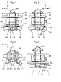
- Fig. 1 to Fig. 4 is a known and common locking arrangement
- a rectangular x, y, z coordinate system is shown chosen and marked with.
- Such locking arrangements contain in particular a locking pin with a bolt head RK and a threaded shaft GS.
- the locking pin is in a locking housing around a vertical, d. H. Parallel to the drawn z-direction Rotary axis DA by means of a hand lever HH manually rotated by about 90 ° between a sketched locking position, in which the container the vehicle is held captive, and a release position, in which a container can be lifted up or placed from above.
- In the sketched Locking position engages over a part of the bolt head a container fitting CB.
- the locking pin is by means of a guided on the threaded shaft clamping nut SM, which is rotatable by hand about the axis of rotation DA, down against the locking housing or a supported in this component clamped.
- the clamping nut protrudes with a conical Section through a lower plate UP of the lock housing through.
- the clamping nut can, as in other common designs, also on be supported by a housing plate.
- the hand lever HH or a functional comparable device for rotating the locking pin can also lie below the clamping nut.
- the unwanted rotation of the clamping nut which z. B. by Shaking movements during driving can be caused by securing means with a gravity drop protection, such. B. in the introduction mentioned state the technique, to prevent.
- the clamping nut is radial in the circumferential direction strongly structured by protrusions and indentations and typically shows the from Fig. 3 clearly visible quadruple star shape.
- a blocking element of Locking means is in the locked position within the maximum radius of Clamping nut in one of the radial indentations between two adjacent projections SV of the star shape.
- the fuse element through a bow bent into a bow a rod material, in particular a round material formed, which in a Swivel bearing about a horizontal pivot axis SA between a in Fig. 1 to Fig. 3 sketched blocking position and a in fig. 4 sketched release position is manually pivoted.
- the bracket In the locked position, the bracket is substantially below, in the release position substantially in the y direction laterally from the vehicle center away from the pivot axis SA. The pivoting movement from the blocking position into the release position thus takes place laterally outward and up.
- the loop-shaped bracket is facing away from the pivot axis with its and to this predominantly parallel, possibly also curved handle portion GA from a user easy to access.
- In the blocking position is preferably a tab SV of the clamping nut inside the loop of the strap.
- the grip portion GA is advantageously below in the locked position the clamping nut and can in the release position advantageously laterally in y direction over the locking housing protrude. In other not sketched Design, the arrangement can also be rotated by about 90 °.
- EA2 With opposite end portions EA1 in the direction of the pivot axis, EA2 advantageously forms the bracket two in the direction of the pivot axis spaced bearing journals of a pivot bearing assembly.
- the pivot bearing pins advantageously extend substantially parallel to the pivot axis and may be directed toward or away from each other.
- One of the Handle portion with the end portions connecting bracket legs serves as izoschenkel AS for supporting a projection SV of the clamping nut against releasing twisting.
- the bracket is in the pivot bearing arrangement stored that the supporting force when planting the projection the clamping nut on the plant leg the axial engagement of the associated end portion EA1 reinforced in the pivot bearing assembly.
- the blocking element is in small extent elastically deformable, so that in such situations themselves using a striking tool, the hanger arms AS elastic can yield without breaking. At the same time, however, the blocking element has a sufficient dimensional stability to prevent unintentional in regular operation Loosening the clamping nut to reliably absorb supporting forces.
- bracket Bent steel bar material easily accessible.
- the ironing material can also be used to advantage, the temple an elastic deformation with bias in the direction of the pivot axis pretend within the pivot bearing assembly.
- the elastic Deformability advantageous for improved securing of the bracket n the locking position be exploited.
- bearing plate LP from below at the clamping nut vertically facing lower housing plate UP of the lock housing attached.
- the attachment is preferably by means of fasteners, such as Screws, rivets, bolts, in particular releasable fasteners.
- the bearing plate is advantageously on the plate of the locking housing fastened after the latch housing is provided with a surface coating, in particular, a corrosion protection layer is provided.
- the bearing plate preferably forms at least a part of the bearing bushes the pivot bearing assembly.
- the bearing bushes up through the lower plate UP of the lock housing and down through formed on the bearing plate, upwardly open cups LS limited.
- the housing plate UP is characterized as a flat plate without special pivot bearing devices particularly advantageous.
- the bearing plate can advantageously by forming a flat sheet metal blank and thus made particularly cheap.
- the bearing plate is advantageously designed in one piece.
- the cups for the two in the direction of Swivel bearing axle spaced from the partial bearing of the pivot bearing assembly a middle part of the bearing plate firmly connected.
- the two bearing shells also formed on two separate partial bearing plates be, which are separately attached to the housing plate separately.
- the blocking element in the preferred sketched example So the bracket BU, from the locked position of FIG. 1 only by overcoming gravity-independent restoring force of an elastically deformable element from the blocking position in the direction of the release position pivoted.
- the retrograde Moment of restoring force is much greater than a Moment from the weight of the locking element itself.
- the remindschwenkende Moment preferably occurs only over a smaller angle section of less as 30 °, preferably less than 15 °, the pivotal movement appreciable in appearance and can be overcome manually by the user without tools.
- the restoring force engages in the region of the pivot bearing arrangement at a short distance from the pivot axis. Particularly advantageous at the Outlined execution is that overcoming the restoring force in the course the pivoting movement of the locking element and the user therefore no separate must perform additional movement.
- the elastic element is preferably the blocking element in the form of in the Swivel bearing elastically prestressed bracket itself.
- the strap lies with his lateral thighs under the elastic bias to the in axial Direction of the pivot axis inwardly facing edges of the bearing shells the bearing plate on. These edges do not run completely in one to Swivel axis vertical transverse plane, but point for the pivoting movement the bracket from the locked position in said angle section a reduced distance by a projection of the edges toward each other on.
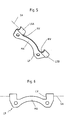
- a preferred embodiment of a bearing plate is shown in Fig. 5 in Outline sketched from below. The distance reduction of the edges is achieved here by a respective locking projection RV at the edges of both bearings. To overcome the locking projections must already biased elastically Temple further narrowed elastically.
- the temple is for clarity Half in Fig. 5 is not shown.
- the height of the locking lugs is preferably lower as half the radius of the cross section.
- the locking projection can also be a Run-up slope with gradually reduced over a larger angle section Have spacing between the flanks of the bearing shells.
- the bearings can in an advantageous embodiment completely around the Axle be closed and independent of a plate of the lock housing form the bearing bushes. This is especially true of Advantage that no contact, in particular no frictional contact between journals the locking element and a corrosion-resistant plate of the locking housing occurs and the corrosion layer is not destroyed.
- the Bearing shells can advantageously under elastic tension of the bearing plates be pressed on the plate UP via the fasteners BE.
- the central portion MA of the bearing plate LP faces the axis of rotation DA cut in a curved manner and can thus be arranged close to the clamping nut be.
- Fig. 7 shows an oblique view of an embodiment with a particularly flat locking housing at the end of a cross member QT of a vehicle.
- the lock housing VG7 to the clarity of the locking pin is not marked with, is partly due to continued plates of the Cross member itself formed and down through an additional lower plate UP7 completed.
- a bearing plate LP7 is by means of screws as fasteners BE on a side plate SPV of the lock housing, which integrally as an extension of a side plate SPQ of the cross member executed, attached.
- the pivot bearing arrangement is here laterally outside of the locking housing and clamping nut occupied Space.
- the pivot axis is parallel to the surface of the side plate SPV or SPQ in y-direction.
- the pivot bushings are in this example completely formed in the bearing plate LP7, so that the bearing pin LZ7 of As a blocking element used bent wire bracket BU7 only on surfaces support the bearing plate LP7 and rub, but not on preferably provided with a corrosion protection side plate.
- the bracket BU7 is angled twice in the course of its side legs and protrudes under the lower plate UP7 in the rotating space of the clamping nut and reliably prevents their unintentional twisting.
- a lock housing VG8 is sketched, which on a vertical Support plate TP8 is attached or such for attachment to a Vehicle has.
- the lock housing is through a top plate OP8 and a U-shaped bent lower part UT formed.
- On a side plate SP8 of the lower part is in Fig. 7 corresponding manner a pivot bearing assembly attached with a bracket as a blocking element.
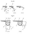
- FIG. 9 shows a view of a housing plate GP (FIG. 9A) and in the direction the pivot axis (Fig. 9B) corresponding to B-B of Fig. 9A a variant a pivot bearing arrangement in which, as in Fig. 7 and Fig. 8, the bearing bushes completely formed by the bearing plate itself by z. B. the Bearing pin LZ9 in the direction of the swivel axis via the bearing shells LS9 protrude. The journals LZ9 of the bracket BU9 do not come into contact with the housing plate GP. The bearing shells have at their side legs of the bracket BU9 again latching projections RV on.
- the bearing plate is divided in the example of FIG. 9 in two partial bearing plates TPA, TPB, each in a defined mutual position on one Housing plate GP to be attached.
- the partial bearing plates are preferably identically constructed.
- the bracket BU9 is in the outlined blocking position, in which in this example, the side legs of the bracket substantially parallel lie to the housing plate, again elastic in the direction of the pivot axis SA biased.
- FIG. 10 is a polygonal, in particular uniformly polygonal, z. B. square or hexagonal rod cross-section of the bracket provided.
- the bearing shell is curved downwards substantially semicircular.
- a plane surface of the journal LQ is advantageously under easier elastic tension of the bearing plate on the lower plate UP of the lock housing at.
- the bearing pin LF is against a round Cross-section flattened on one side and lies in the sketched in Fig. 11A blocking position with the flat cross section on a counter surface of a prestressed Spring tongue FZ on.
- the release position is the preferably elastically biased spring tongue pushed up by further elastic deformation.
- the spring tongue prevents at the same time, that the bearing pin LF in contact with the housing plate UP comes.
- the blocking element is only frictionally engaged held. It can u. U. again the effect of the automatic reset occur under the effect of vibration while driving.
- the arrangement of the pivot bearing on a plate of the locking housing and / or the securing of the blocking element by a restoring force of an elastic deformable element are particularly advantageous in a locking arrangement with removable, height-adjustable or swiveling Lock housing in a vehicle-mounted bracket.
Landscapes
- Engineering & Computer Science (AREA)
- Transportation (AREA)
- Mechanical Engineering (AREA)
- Clamps And Clips (AREA)
- Pivots And Pivotal Connections (AREA)
- Lock And Its Accessories (AREA)
- Connection Of Plates (AREA)
- Refuge Islands, Traffic Blockers, Or Guard Fence (AREA)
- Hooks, Suction Cups, And Attachment By Adhesive Means (AREA)
Abstract
Description
- Fig. 1
- eine twist-lock-Verriegelung mit gesperrter Spannmutter,
- Fig. 2
- eine zu Fig. 1 um 90° gedrehte Seitenansicht,
- Fig. 3
- eine Ansicht zu Fig. 1 von unten,
- Fig. 4
- eine Ansicht analog Fig. 2 mit dem Sperrelement in Freigabestellung,
- Fig. 5
- eine Schrägansicht einer Lagerplatte,
- Fig. 6
- eine Variation zu Fig. 5,
- Fig. 7
- ein Verriegelungsgehäuse mit einer seitlich an einem Schwenklagergehäuse befestigten Lagerplatte,
- Fig. 8
- eine Abwandlung zu Fig. 7,
- Fig. 9
- eine Schwenklageranordnung mit zwei Teillagerplatten,
- Fig. 10
- ein Schwenklager mit einem nicht rundem Lagerzapfen,
- Fig. 11
- ein weiteres Schwenklager mit nicht rundem Lagerzapfen.
Claims (19)
- Verriegelungsanordnung zur Festlegung von Containern auf Lastfahrzeugen mit einem Riegelzapfen, welcher einen zum Eingriff in einem Containerbeschlag ausgebildeten Riegelkopf (RK) und einem Gewindeschaft (GS) aufweist, mit einer den Gewindeschaft umgreifenden Spannmutter (SM) und mit Sicherungseinrichtung, welche in einer Sperrstellung ein Lösen der Spannmutter verhindern und manuell in eine Lösestellung verlagerbar sind, dadurch gekennzeichnet, dassund/oderdie Sicherungseinrichtungen ein schwenkbares Sperrelement (BU) enthalten, welches nach oder unter Überwindung einer manuell werkzeuglos von einem Benutzer überwindbaren, schwerkraftunabhängigen Rückstellkraft eines elastisch verformbaren Elements von der Sperrstellung in Richtung der Lösestellung verschwenkbar ist,und/oderdie Sicherungseinrichtungen ein zwischen einer Sperrstellung und einer Lösestellung schwenkbares Sperrelement (BU) enthalten und ein Schwenklager für das Sperrelement zumindest teilweise durch eine an einer Gehäuseplatte (UP,) eines Verriegelungsgehäuses angeordnete und an der Gehäuseplatte befestigte Lagerplatte (LP) gebildet ist,ein das Lösen der Spannmutter (SM) verhinderndes Sperrelement (BU) der Sicherungseinrichtungen bruchfest und in Öffnungsrichtung der Spannmutter begrenzt elastisch nachgebend ausgebildet und/oder in einem Schwenklager elastisch nachgebend gelagert ist.
- Anordnung nach Anspruch 1, dadurch gekennzeichnet, dass das elastisch verformbare Element durch das Sperrelement selbst gegeben ist.
- Anordnung nach Anspruch 1 oder 2, dadurch gekennzeichnet, dass das elastische Element durch ein Teil eines Schwenklagers für das Sperrelement gebildet ist.
- Anordnung nach einem der Ansprüche 1 bis 3, dadurch gekennzeichnet, dass das Sperrelement durch eine von einem Benutzer manuell überwindbare Haltekraft in der Lösestellung gehalten ist.
- Anordnung nach Anspruch 4, dadurch gekennzeichnet, dass die Haltekraft durch Reibschluss des Sperrelements aufgebracht ist.
- Anordnung nach Anspruch 4 oder 5, dadurch gekennzeichnet, dass die Haltekraft durch eine Rückstellkraft eines elastisch verformbaren Elements gebildet ist.
- Anordnung nach einem der Ansprüche 1 bis 6, dadurch gekennzeichnet, dass das Sperrelement eine Bügelschleife bildet.
- Anordnung nach Anspruch 7, dadurch gekennzeichnet, dass die Bügelschleife in der Sperrstellung in Richtung der Schwenkachse elastisch vorgespannt ist.
- Anordnung nach einem der Ansprüche 1 bis 8, dadurch gekennzeichnet, dass das Sperrelement (BU) aus einem gebogenen Stabmaterial gebildet ist.
- Anordnung nach einem der Ansprüche 1 bis 9, dadurch gekennzeichnet, dass bei der Schwenkbewegung wenigstens ein Bügelschenkel (AS) an einem Vorsprung (RL, LV) einer Führungsfläche entlang gleitet und an dem Vorsprung elastisch verformt wird.
- Anordnung nach Anspruch 10, dadurch gekennzeichnet, dass der Vorsprung eine Rastnase (RV) bildet.
- Anordnung nach einem der Ansprüche 1 bis 11, dadurch gekennzeichnet, dass das Schwenklager zwei in Richtung der Schwenkachse (SA) beabstandete Teillager aufweist.
- Anordnung nach einem der Ansprüche 1 bis 12, dadurch gekennzeichnet, dass das Schwenklager durch eine Lagerschale (LSA, LSB) der Lagerplatte (LP) und die Gehäuseplatte (UP) gebildet ist.
- Anordnung nach einem der Ansprüche 1 bis 13, dadurch gekennzeichnet, dass die Lagerplatte (LP) mittels Befestigungselementen an der Gehäuseplatte befestigt ist.
- Anordnung nach einem der Ansprüche 1 bis 14, dadurch gekennzeichnet, dass die Gehäuseplatte mit einer Korrosionsschutzschicht versehen ist.
- Anordnung nach einem der Ansprüche 1 bis 15, dadurch gekennzeichnet, dass die Gehäuseplatte der Spannmutter vertikal gegenüber steht und dass die Unterkante der Schwenklageranordnung von der Gehäuseplatte in Richtung der Spannmutter um maximal 35 mm, insbesondere maximal 25 mm beabstandet ist.
- Anordnung nach einem der Ansprüche 1 bis 16, dadurch gekennzeichnet, dass die Lagerplatte an einer seitlichen, insbesondere im wesentlichen vertikalen Gehäuseplatte befestigt ist.
- Anordnung nach einem der Ansprüche 1 bis 17, dadurch gekennzeichnet, dass die Lagerplatte zwei separat an der Gehäuseplatte befestigte Teillagerplatten umfasst.
- Anordnung nach einem der Ansprüche 1 bis 16, dadurch gekennzeichnet, dass das Verriegelungsgehäuse innerhalb einer Halterung höhenverstellbar und/oder verschwenkbar ist.
Applications Claiming Priority (2)
| Application Number | Priority Date | Filing Date | Title |
|---|---|---|---|
| DE102004014321 | 2004-03-22 | ||
| DE102004014321A DE102004014321A1 (de) | 2004-03-22 | 2004-03-22 | Verriegelungsanordnung zur Festlegung von Containern auf Lastfahrzeugen |
Publications (3)
| Publication Number | Publication Date |
|---|---|
| EP1580073A2 true EP1580073A2 (de) | 2005-09-28 |
| EP1580073A3 EP1580073A3 (de) | 2007-07-04 |
| EP1580073B1 EP1580073B1 (de) | 2008-11-05 |
Family
ID=34854021
Family Applications (1)
| Application Number | Title | Priority Date | Filing Date |
|---|---|---|---|
| EP05003349A Expired - Lifetime EP1580073B1 (de) | 2004-03-22 | 2005-02-17 | Verriegelungsanordnung zur Festlegung von Containern auf Lastfahrzeugen |
Country Status (4)
| Country | Link |
|---|---|
| EP (1) | EP1580073B1 (de) |
| AT (1) | ATE413307T1 (de) |
| DE (3) | DE102004014321A1 (de) |
| ES (1) | ES2315746T3 (de) |
Cited By (3)
| Publication number | Priority date | Publication date | Assignee | Title |
|---|---|---|---|---|
| CN104684822A (zh) * | 2012-06-26 | 2015-06-03 | 诺伊兰贝通H.布里吉两合公司(有限责任公司) | 锁紧装置 |
| DE202016001996U1 (de) | 2016-03-24 | 2016-06-10 | Helmut Fliegl | Verriegelungsvorrichtung für Lastfahrzeuge |
| CN111086771A (zh) * | 2020-01-21 | 2020-05-01 | 大连中集特种物流装备有限公司 | 散货集装箱 |
Families Citing this family (1)
| Publication number | Priority date | Publication date | Assignee | Title |
|---|---|---|---|---|
| RU2657920C2 (ru) * | 2016-05-12 | 2018-06-18 | Общество с ограниченной ответственностью Управляющая Компания "РэйлТрансХолдинг" | Железнодорожная вагон-платформа для перевозки контейнеров повышенной грузоподъемности |
Family Cites Families (9)
| Publication number | Priority date | Publication date | Assignee | Title |
|---|---|---|---|---|
| DE7303850U (de) * | 1973-05-10 | Wihag Westfaelische Industrie Und Handels Gmbh & Co Kg | Container Verriegelung | |
| DE2049927A1 (de) * | 1970-10-10 | 1972-04-13 | Gebr. Vielhaben Präzisions werkzeugfabrik, 2000 Norderstedt | Doppelt gesicherte Container-Befestigung auf Fahrzeugen |
| DE7135647U (de) * | 1971-09-20 | 1971-12-16 | Faka Gmbh | Verriegelungseinrichtung an Fahrzeugen oder dgl. für Container oder dgl |
| DE2209804A1 (de) * | 1972-03-01 | 1973-09-06 | Bueckeburg Faka Fahrzeug | Verriegelungseinrichtung an fahrzeugen oder dgl. fuer container oder dgl |
| DE2305001A1 (de) * | 1973-02-01 | 1974-08-08 | Wihag Westfael Ind | Absenkbare verriegelung fuer container und wechselaufbauten |
| DE2443554A1 (de) * | 1974-09-11 | 1976-03-25 | Peck & Hale | Vorrichtung mit schloss zum festlegen und/oder verblocken gestapelter elemente |
| DE8522360U1 (de) * | 1985-08-02 | 1985-09-26 | Gerd Schulz Fahrzeug- und Container-Technik, 2100 Hamburg | Containerverriegelung |
| DE19603817A1 (de) * | 1996-02-02 | 1997-10-09 | Gerd Schulz | Vorrichtung zur Verriegelung eines Containers an einem Fahrzeugchassis |
| DE19804771C2 (de) | 1998-02-06 | 2000-06-15 | Schneider Fahrzeug Und Contain | Verriegelungsvorrichtung für Container-Transportfahrzeuge |
-
2004
- 2004-03-22 DE DE102004014321A patent/DE102004014321A1/de not_active Withdrawn
-
2005
- 2005-02-17 EP EP05003349A patent/EP1580073B1/de not_active Expired - Lifetime
- 2005-02-17 ES ES05003349T patent/ES2315746T3/es not_active Expired - Lifetime
- 2005-02-17 DE DE502005005844T patent/DE502005005844D1/de not_active Expired - Lifetime
- 2005-02-17 DE DE202005021542U patent/DE202005021542U1/de not_active Expired - Lifetime
- 2005-02-17 AT AT05003349T patent/ATE413307T1/de not_active IP Right Cessation
Cited By (4)
| Publication number | Priority date | Publication date | Assignee | Title |
|---|---|---|---|---|
| CN104684822A (zh) * | 2012-06-26 | 2015-06-03 | 诺伊兰贝通H.布里吉两合公司(有限责任公司) | 锁紧装置 |
| CN104684822B (zh) * | 2012-06-26 | 2017-05-10 | 诺伊兰贝通H.布里吉两合公司(有限责任公司) | 锁紧装置 |
| DE202016001996U1 (de) | 2016-03-24 | 2016-06-10 | Helmut Fliegl | Verriegelungsvorrichtung für Lastfahrzeuge |
| CN111086771A (zh) * | 2020-01-21 | 2020-05-01 | 大连中集特种物流装备有限公司 | 散货集装箱 |
Also Published As
| Publication number | Publication date |
|---|---|
| EP1580073B1 (de) | 2008-11-05 |
| DE502005005844D1 (de) | 2008-12-18 |
| ES2315746T3 (es) | 2009-04-01 |
| DE102004014321A1 (de) | 2005-10-06 |
| ATE413307T1 (de) | 2008-11-15 |
| DE202005021542U1 (de) | 2008-07-10 |
| EP1580073A3 (de) | 2007-07-04 |
Similar Documents
| Publication | Publication Date | Title |
|---|---|---|
| EP3607213B1 (de) | Lochwandsystem und befestigungselement | |
| DE69004548T2 (de) | Schnell montierbare mutter. | |
| DE60109406T2 (de) | Befestigungsvorrichtung für Platten | |
| DE2217490B2 (de) | Halterung einer schwimmend gelagerten mutter an einem werkstueck | |
| DE19929966A1 (de) | Sicherungssystem für einen Bolzen und eine Mutter | |
| DE69220872T2 (de) | Sicherungsvorrichtung für Schraubenbolzen | |
| DE3134179A1 (de) | "stossfeste fussrollenanordung" | |
| EP2698296B1 (de) | Längenverstellbares Teleskoprohr | |
| DE102017009176A1 (de) | Kupplungsvorrichtung | |
| EP2412660A1 (de) | Flacher Verzurrpunkt | |
| EP1580073B1 (de) | Verriegelungsanordnung zur Festlegung von Containern auf Lastfahrzeugen | |
| EP3299332B1 (de) | Anschlag- oder zurrlasche, befestigungssockel für eine anschlag- oder zurrlasche sowie anschlag- oder zurrpunkt mit einer anschlag- oder zurrlasche und befestigungssockel | |
| DE102012103815A1 (de) | Verzurrhakenelement sowie System zum Verzurren von Ladungen auf Ladeflächen, insbesondere zur Befestigung von Ladungen auf Transportblechen | |
| EP3722244B1 (de) | Wirbelringschraube | |
| DE10003868A1 (de) | Dachgepäckhalteranordnung für Kraftfahrzeuge | |
| DE4336762C1 (de) | Befestigungseinrichtung | |
| DE10013845C2 (de) | Anschlußvorrichtung | |
| DE202019101309U1 (de) | Schraubenschlüssel und Schraubenschlüssel-Aufbau zum schnellen Drehen | |
| DE102017102665B4 (de) | Stahlaktivator für Container-Twistlocks | |
| EP0638462B1 (de) | Stützfuss für Dachlastenträger für Kraftfahrzeuge | |
| DE19900839B4 (de) | Riegelelement | |
| DE102004025475B4 (de) | Verriegelungsvorrichtung, insbesondere für Fahrzeugsitz | |
| DE102012025165A1 (de) | Befestigungsvorrichtung | |
| EP3599130B1 (de) | Hakenelement und spanngurt mit hakenelementen | |
| DE60008696T2 (de) | Lastenträger für ein Kraftfahrzeug sowie Kraftfahrzeug mit einem Lastenträger |
Legal Events
| Date | Code | Title | Description |
|---|---|---|---|
| PUAI | Public reference made under article 153(3) epc to a published international application that has entered the european phase |
Free format text: ORIGINAL CODE: 0009012 |
|
| AK | Designated contracting states |
Kind code of ref document: A2 Designated state(s): AT BE BG CH CY CZ DE DK EE ES FI FR GB GR HU IE IS IT LI LT LU MC NL PL PT RO SE SI SK TR |
|
| AX | Request for extension of the european patent |
Extension state: AL BA HR LV MK YU |
|
| PUAL | Search report despatched |
Free format text: ORIGINAL CODE: 0009013 |
|
| AK | Designated contracting states |
Kind code of ref document: A3 Designated state(s): AT BE BG CH CY CZ DE DK EE ES FI FR GB GR HU IE IS IT LI LT LU MC NL PL PT RO SE SI SK TR |
|
| AX | Request for extension of the european patent |
Extension state: AL BA HR LV MK YU |
|
| 17P | Request for examination filed |
Effective date: 20070807 |
|
| 17Q | First examination report despatched |
Effective date: 20070907 |
|
| AKX | Designation fees paid |
Designated state(s): AT BE BG CH CY CZ DE DK EE ES FI FR GB GR HU IE IS IT LI LT LU MC NL PL PT RO SE SI SK TR |
|
| GRAP | Despatch of communication of intention to grant a patent |
Free format text: ORIGINAL CODE: EPIDOSNIGR1 |
|
| GRAS | Grant fee paid |
Free format text: ORIGINAL CODE: EPIDOSNIGR3 |
|
| GRAA | (expected) grant |
Free format text: ORIGINAL CODE: 0009210 |
|
| AK | Designated contracting states |
Kind code of ref document: B1 Designated state(s): AT BE BG CH CY CZ DE DK EE ES FI FR GB GR HU IE IS IT LI LT LU MC NL PL PT RO SE SI SK TR |
|
| REG | Reference to a national code |
Ref country code: GB Ref legal event code: FG4D Free format text: NOT ENGLISH |
|
| REG | Reference to a national code |
Ref country code: CH Ref legal event code: EP |
|
| REG | Reference to a national code |
Ref country code: IE Ref legal event code: FG4D Free format text: LANGUAGE OF EP DOCUMENT: GERMAN |
|
| REF | Corresponds to: |
Ref document number: 502005005844 Country of ref document: DE Date of ref document: 20081218 Kind code of ref document: P |
|
| REG | Reference to a national code |
Ref country code: ES Ref legal event code: FG2A Ref document number: 2315746 Country of ref document: ES Kind code of ref document: T3 |
|
| LTIE | Lt: invalidation of european patent or patent extension |
Effective date: 20081105 |
|
| PG25 | Lapsed in a contracting state [announced via postgrant information from national office to epo] |
Ref country code: LT Free format text: LAPSE BECAUSE OF FAILURE TO SUBMIT A TRANSLATION OF THE DESCRIPTION OR TO PAY THE FEE WITHIN THE PRESCRIBED TIME-LIMIT Effective date: 20081105 |
|
| PG25 | Lapsed in a contracting state [announced via postgrant information from national office to epo] |
Ref country code: FI Free format text: LAPSE BECAUSE OF FAILURE TO SUBMIT A TRANSLATION OF THE DESCRIPTION OR TO PAY THE FEE WITHIN THE PRESCRIBED TIME-LIMIT Effective date: 20081105 Ref country code: IS Free format text: LAPSE BECAUSE OF FAILURE TO SUBMIT A TRANSLATION OF THE DESCRIPTION OR TO PAY THE FEE WITHIN THE PRESCRIBED TIME-LIMIT Effective date: 20090305 Ref country code: SI Free format text: LAPSE BECAUSE OF FAILURE TO SUBMIT A TRANSLATION OF THE DESCRIPTION OR TO PAY THE FEE WITHIN THE PRESCRIBED TIME-LIMIT Effective date: 20081105 Ref country code: PL Free format text: LAPSE BECAUSE OF FAILURE TO SUBMIT A TRANSLATION OF THE DESCRIPTION OR TO PAY THE FEE WITHIN THE PRESCRIBED TIME-LIMIT Effective date: 20081105 |
|
| REG | Reference to a national code |
Ref country code: IE Ref legal event code: FD4D |
|
| PG25 | Lapsed in a contracting state [announced via postgrant information from national office to epo] |
Ref country code: IE Free format text: LAPSE BECAUSE OF FAILURE TO SUBMIT A TRANSLATION OF THE DESCRIPTION OR TO PAY THE FEE WITHIN THE PRESCRIBED TIME-LIMIT Effective date: 20081105 Ref country code: DK Free format text: LAPSE BECAUSE OF FAILURE TO SUBMIT A TRANSLATION OF THE DESCRIPTION OR TO PAY THE FEE WITHIN THE PRESCRIBED TIME-LIMIT Effective date: 20081105 Ref country code: RO Free format text: LAPSE BECAUSE OF FAILURE TO SUBMIT A TRANSLATION OF THE DESCRIPTION OR TO PAY THE FEE WITHIN THE PRESCRIBED TIME-LIMIT Effective date: 20081105 Ref country code: EE Free format text: LAPSE BECAUSE OF FAILURE TO SUBMIT A TRANSLATION OF THE DESCRIPTION OR TO PAY THE FEE WITHIN THE PRESCRIBED TIME-LIMIT Effective date: 20081105 Ref country code: BG Free format text: LAPSE BECAUSE OF FAILURE TO SUBMIT A TRANSLATION OF THE DESCRIPTION OR TO PAY THE FEE WITHIN THE PRESCRIBED TIME-LIMIT Effective date: 20090205 |
|
| PG25 | Lapsed in a contracting state [announced via postgrant information from national office to epo] |
Ref country code: CZ Free format text: LAPSE BECAUSE OF FAILURE TO SUBMIT A TRANSLATION OF THE DESCRIPTION OR TO PAY THE FEE WITHIN THE PRESCRIBED TIME-LIMIT Effective date: 20081105 Ref country code: SE Free format text: LAPSE BECAUSE OF FAILURE TO SUBMIT A TRANSLATION OF THE DESCRIPTION OR TO PAY THE FEE WITHIN THE PRESCRIBED TIME-LIMIT Effective date: 20090205 Ref country code: PT Free format text: LAPSE BECAUSE OF FAILURE TO SUBMIT A TRANSLATION OF THE DESCRIPTION OR TO PAY THE FEE WITHIN THE PRESCRIBED TIME-LIMIT Effective date: 20090406 |
|
| PLBE | No opposition filed within time limit |
Free format text: ORIGINAL CODE: 0009261 |
|
| STAA | Information on the status of an ep patent application or granted ep patent |
Free format text: STATUS: NO OPPOSITION FILED WITHIN TIME LIMIT |
|
| PG25 | Lapsed in a contracting state [announced via postgrant information from national office to epo] |
Ref country code: MC Free format text: LAPSE BECAUSE OF NON-PAYMENT OF DUE FEES Effective date: 20090228 Ref country code: SK Free format text: LAPSE BECAUSE OF FAILURE TO SUBMIT A TRANSLATION OF THE DESCRIPTION OR TO PAY THE FEE WITHIN THE PRESCRIBED TIME-LIMIT Effective date: 20081105 |
|
| REG | Reference to a national code |
Ref country code: CH Ref legal event code: PL |
|
| 26N | No opposition filed |
Effective date: 20090806 |
|
| GBPC | Gb: european patent ceased through non-payment of renewal fee |
Effective date: 20090217 |
|
| PG25 | Lapsed in a contracting state [announced via postgrant information from national office to epo] |
Ref country code: LI Free format text: LAPSE BECAUSE OF NON-PAYMENT OF DUE FEES Effective date: 20090228 Ref country code: CH Free format text: LAPSE BECAUSE OF NON-PAYMENT OF DUE FEES Effective date: 20090228 |
|
| PG25 | Lapsed in a contracting state [announced via postgrant information from national office to epo] |
Ref country code: GB Free format text: LAPSE BECAUSE OF NON-PAYMENT OF DUE FEES Effective date: 20090217 |
|
| PG25 | Lapsed in a contracting state [announced via postgrant information from national office to epo] |
Ref country code: AT Free format text: LAPSE BECAUSE OF NON-PAYMENT OF DUE FEES Effective date: 20090217 |
|
| PG25 | Lapsed in a contracting state [announced via postgrant information from national office to epo] |
Ref country code: GR Free format text: LAPSE BECAUSE OF FAILURE TO SUBMIT A TRANSLATION OF THE DESCRIPTION OR TO PAY THE FEE WITHIN THE PRESCRIBED TIME-LIMIT Effective date: 20090206 |
|
| PG25 | Lapsed in a contracting state [announced via postgrant information from national office to epo] |
Ref country code: IT Free format text: LAPSE BECAUSE OF FAILURE TO SUBMIT A TRANSLATION OF THE DESCRIPTION OR TO PAY THE FEE WITHIN THE PRESCRIBED TIME-LIMIT Effective date: 20081105 |
|
| PG25 | Lapsed in a contracting state [announced via postgrant information from national office to epo] |
Ref country code: LU Free format text: LAPSE BECAUSE OF NON-PAYMENT OF DUE FEES Effective date: 20090217 |
|
| PG25 | Lapsed in a contracting state [announced via postgrant information from national office to epo] |
Ref country code: HU Free format text: LAPSE BECAUSE OF FAILURE TO SUBMIT A TRANSLATION OF THE DESCRIPTION OR TO PAY THE FEE WITHIN THE PRESCRIBED TIME-LIMIT Effective date: 20090506 |
|
| PG25 | Lapsed in a contracting state [announced via postgrant information from national office to epo] |
Ref country code: TR Free format text: LAPSE BECAUSE OF FAILURE TO SUBMIT A TRANSLATION OF THE DESCRIPTION OR TO PAY THE FEE WITHIN THE PRESCRIBED TIME-LIMIT Effective date: 20081105 |
|
| PG25 | Lapsed in a contracting state [announced via postgrant information from national office to epo] |
Ref country code: CY Free format text: LAPSE BECAUSE OF FAILURE TO SUBMIT A TRANSLATION OF THE DESCRIPTION OR TO PAY THE FEE WITHIN THE PRESCRIBED TIME-LIMIT Effective date: 20081105 |
|
| REG | Reference to a national code |
Ref country code: DE Ref legal event code: R082 Ref document number: 502005005844 Country of ref document: DE Representative=s name: GERHARD WEBER, DE |
|
| PGFP | Annual fee paid to national office [announced via postgrant information from national office to epo] |
Ref country code: FR Payment date: 20120228 Year of fee payment: 8 |
|
| REG | Reference to a national code |
Ref country code: DE Ref legal event code: R082 Ref document number: 502005005844 Country of ref document: DE Representative=s name: WEBER, GERHARD, DIPL.-PHYS., DE Effective date: 20120402 Ref country code: DE Ref legal event code: R081 Ref document number: 502005005844 Country of ref document: DE Owner name: SCHMITZ CARGOBULL GOTHA GMBH, DE Free format text: FORMER OWNER: SCHMITZ GOTHA FAHRZEUGWERKE GMBH, 99867 GOTHA, DE Effective date: 20120402 |
|
| PGFP | Annual fee paid to national office [announced via postgrant information from national office to epo] |
Ref country code: DE Payment date: 20120229 Year of fee payment: 8 |
|
| PGFP | Annual fee paid to national office [announced via postgrant information from national office to epo] |
Ref country code: BE Payment date: 20120221 Year of fee payment: 8 |
|
| PGFP | Annual fee paid to national office [announced via postgrant information from national office to epo] |
Ref country code: NL Payment date: 20120224 Year of fee payment: 8 |
|
| PGFP | Annual fee paid to national office [announced via postgrant information from national office to epo] |
Ref country code: ES Payment date: 20120221 Year of fee payment: 8 |
|
| BERE | Be: lapsed |
Owner name: SCHMITZ GOTHA FAHRZEUGWERKE G.M.B.H. Effective date: 20130228 |
|
| REG | Reference to a national code |
Ref country code: NL Ref legal event code: V1 Effective date: 20130901 |
|
| PG25 | Lapsed in a contracting state [announced via postgrant information from national office to epo] |
Ref country code: NL Free format text: LAPSE BECAUSE OF NON-PAYMENT OF DUE FEES Effective date: 20130901 |
|
| REG | Reference to a national code |
Ref country code: FR Ref legal event code: ST Effective date: 20131031 |
|
| REG | Reference to a national code |
Ref country code: DE Ref legal event code: R119 Ref document number: 502005005844 Country of ref document: DE Effective date: 20130903 |
|
| PG25 | Lapsed in a contracting state [announced via postgrant information from national office to epo] |
Ref country code: BE Free format text: LAPSE BECAUSE OF NON-PAYMENT OF DUE FEES Effective date: 20130228 Ref country code: DE Free format text: LAPSE BECAUSE OF NON-PAYMENT OF DUE FEES Effective date: 20130903 Ref country code: FR Free format text: LAPSE BECAUSE OF NON-PAYMENT OF DUE FEES Effective date: 20130228 |
|
| REG | Reference to a national code |
Ref country code: ES Ref legal event code: FD2A Effective date: 20140408 |
|
| PG25 | Lapsed in a contracting state [announced via postgrant information from national office to epo] |
Ref country code: ES Free format text: LAPSE BECAUSE OF NON-PAYMENT OF DUE FEES Effective date: 20130218 |