EP1580092B1 - Caméra pour un véhicule automobile - Google Patents
Caméra pour un véhicule automobile Download PDFInfo
- Publication number
- EP1580092B1 EP1580092B1 EP05100746.6A EP05100746A EP1580092B1 EP 1580092 B1 EP1580092 B1 EP 1580092B1 EP 05100746 A EP05100746 A EP 05100746A EP 1580092 B1 EP1580092 B1 EP 1580092B1
- Authority
- EP
- European Patent Office
- Prior art keywords
- camera
- image sensor
- optical radiation
- optical
- radiation
- Prior art date
- Legal status (The legal status is an assumption and is not a legal conclusion. Google has not performed a legal analysis and makes no representation as to the accuracy of the status listed.)
- Ceased
Links
Images

Classifications
-
- G—PHYSICS
- G03—PHOTOGRAPHY; CINEMATOGRAPHY; ANALOGOUS TECHNIQUES USING WAVES OTHER THAN OPTICAL WAVES; ELECTROGRAPHY; HOLOGRAPHY
- G03B—APPARATUS OR ARRANGEMENTS FOR TAKING PHOTOGRAPHS OR FOR PROJECTING OR VIEWING THEM; APPARATUS OR ARRANGEMENTS EMPLOYING ANALOGOUS TECHNIQUES USING WAVES OTHER THAN OPTICAL WAVES; ACCESSORIES THEREFOR
- G03B19/00—Cameras
- G03B19/02—Still-picture cameras
- G03B19/023—Multi-image cameras
-
- B—PERFORMING OPERATIONS; TRANSPORTING
- B60—VEHICLES IN GENERAL
- B60R—VEHICLES, VEHICLE FITTINGS, OR VEHICLE PARTS, NOT OTHERWISE PROVIDED FOR
- B60R1/00—Optical viewing arrangements; Real-time viewing arrangements for drivers or passengers using optical image capturing systems, e.g. cameras or video systems specially adapted for use in or on vehicles
- B60R1/20—Real-time viewing arrangements for drivers or passengers using optical image capturing systems, e.g. cameras or video systems specially adapted for use in or on vehicles
- B60R1/30—Real-time viewing arrangements for drivers or passengers using optical image capturing systems, e.g. cameras or video systems specially adapted for use in or on vehicles providing vision in the non-visible spectrum, e.g. night or infrared vision
-
- B—PERFORMING OPERATIONS; TRANSPORTING
- B60—VEHICLES IN GENERAL
- B60R—VEHICLES, VEHICLE FITTINGS, OR VEHICLE PARTS, NOT OTHERWISE PROVIDED FOR
- B60R1/00—Optical viewing arrangements; Real-time viewing arrangements for drivers or passengers using optical image capturing systems, e.g. cameras or video systems specially adapted for use in or on vehicles
- B60R1/20—Real-time viewing arrangements for drivers or passengers using optical image capturing systems, e.g. cameras or video systems specially adapted for use in or on vehicles
- B60R1/22—Real-time viewing arrangements for drivers or passengers using optical image capturing systems, e.g. cameras or video systems specially adapted for use in or on vehicles for viewing an area outside the vehicle, e.g. the exterior of the vehicle
- B60R1/23—Real-time viewing arrangements for drivers or passengers using optical image capturing systems, e.g. cameras or video systems specially adapted for use in or on vehicles for viewing an area outside the vehicle, e.g. the exterior of the vehicle with a predetermined field of view
-
- B—PERFORMING OPERATIONS; TRANSPORTING
- B60—VEHICLES IN GENERAL
- B60S—SERVICING, CLEANING, REPAIRING, SUPPORTING, LIFTING, OR MANOEUVRING OF VEHICLES, NOT OTHERWISE PROVIDED FOR
- B60S1/00—Cleaning of vehicles
- B60S1/02—Cleaning windscreens, windows or optical devices
- B60S1/04—Wipers or the like, e.g. scrapers
- B60S1/06—Wipers or the like, e.g. scrapers characterised by the drive
- B60S1/08—Wipers or the like, e.g. scrapers characterised by the drive electrically driven
- B60S1/0818—Wipers or the like, e.g. scrapers characterised by the drive electrically driven including control systems responsive to external conditions, e.g. by detection of moisture, dirt or the like
- B60S1/0822—Wipers or the like, e.g. scrapers characterised by the drive electrically driven including control systems responsive to external conditions, e.g. by detection of moisture, dirt or the like characterized by the arrangement or type of detection means
-
- B—PERFORMING OPERATIONS; TRANSPORTING
- B60—VEHICLES IN GENERAL
- B60S—SERVICING, CLEANING, REPAIRING, SUPPORTING, LIFTING, OR MANOEUVRING OF VEHICLES, NOT OTHERWISE PROVIDED FOR
- B60S1/00—Cleaning of vehicles
- B60S1/02—Cleaning windscreens, windows or optical devices
- B60S1/04—Wipers or the like, e.g. scrapers
- B60S1/06—Wipers or the like, e.g. scrapers characterised by the drive
- B60S1/08—Wipers or the like, e.g. scrapers characterised by the drive electrically driven
- B60S1/0818—Wipers or the like, e.g. scrapers characterised by the drive electrically driven including control systems responsive to external conditions, e.g. by detection of moisture, dirt or the like
- B60S1/0822—Wipers or the like, e.g. scrapers characterised by the drive electrically driven including control systems responsive to external conditions, e.g. by detection of moisture, dirt or the like characterized by the arrangement or type of detection means
- B60S1/0833—Optical rain sensor
- B60S1/0844—Optical rain sensor including a camera
-
- G—PHYSICS
- G03—PHOTOGRAPHY; CINEMATOGRAPHY; ANALOGOUS TECHNIQUES USING WAVES OTHER THAN OPTICAL WAVES; ELECTROGRAPHY; HOLOGRAPHY
- G03B—APPARATUS OR ARRANGEMENTS FOR TAKING PHOTOGRAPHS OR FOR PROJECTING OR VIEWING THEM; APPARATUS OR ARRANGEMENTS EMPLOYING ANALOGOUS TECHNIQUES USING WAVES OTHER THAN OPTICAL WAVES; ACCESSORIES THEREFOR
- G03B15/00—Special procedures for taking photographs; Apparatus therefor
- G03B15/02—Illuminating scene
- G03B15/03—Combinations of cameras with lighting apparatus; Flash units
- G03B15/05—Combinations of cameras with electronic flash apparatus; Electronic flash units
-
- G—PHYSICS
- G03—PHOTOGRAPHY; CINEMATOGRAPHY; ANALOGOUS TECHNIQUES USING WAVES OTHER THAN OPTICAL WAVES; ELECTROGRAPHY; HOLOGRAPHY
- G03B—APPARATUS OR ARRANGEMENTS FOR TAKING PHOTOGRAPHS OR FOR PROJECTING OR VIEWING THEM; APPARATUS OR ARRANGEMENTS EMPLOYING ANALOGOUS TECHNIQUES USING WAVES OTHER THAN OPTICAL WAVES; ACCESSORIES THEREFOR
- G03B17/00—Details of cameras or camera bodies; Accessories therefor
- G03B17/02—Bodies
-
- G—PHYSICS
- G06—COMPUTING OR CALCULATING; COUNTING
- G06V—IMAGE OR VIDEO RECOGNITION OR UNDERSTANDING
- G06V20/00—Scenes; Scene-specific elements
- G06V20/50—Context or environment of the image
- G06V20/56—Context or environment of the image exterior to a vehicle by using sensors mounted on the vehicle
-
- H—ELECTRICITY
- H04—ELECTRIC COMMUNICATION TECHNIQUE
- H04N—PICTORIAL COMMUNICATION, e.g. TELEVISION
- H04N23/00—Cameras or camera modules comprising electronic image sensors; Control thereof
- H04N23/56—Cameras or camera modules comprising electronic image sensors; Control thereof provided with illuminating means
-
- H—ELECTRICITY
- H04—ELECTRIC COMMUNICATION TECHNIQUE
- H04N—PICTORIAL COMMUNICATION, e.g. TELEVISION
- H04N23/00—Cameras or camera modules comprising electronic image sensors; Control thereof
- H04N23/70—Circuitry for compensating brightness variation in the scene
- H04N23/74—Circuitry for compensating brightness variation in the scene by influencing the scene brightness using illuminating means
-
- B—PERFORMING OPERATIONS; TRANSPORTING
- B60—VEHICLES IN GENERAL
- B60R—VEHICLES, VEHICLE FITTINGS, OR VEHICLE PARTS, NOT OTHERWISE PROVIDED FOR
- B60R2300/00—Details of viewing arrangements using cameras and displays, specially adapted for use in a vehicle
- B60R2300/10—Details of viewing arrangements using cameras and displays, specially adapted for use in a vehicle characterised by the type of camera system used
- B60R2300/106—Details of viewing arrangements using cameras and displays, specially adapted for use in a vehicle characterised by the type of camera system used using night vision cameras
-
- B—PERFORMING OPERATIONS; TRANSPORTING
- B60—VEHICLES IN GENERAL
- B60R—VEHICLES, VEHICLE FITTINGS, OR VEHICLE PARTS, NOT OTHERWISE PROVIDED FOR
- B60R2300/00—Details of viewing arrangements using cameras and displays, specially adapted for use in a vehicle
- B60R2300/10—Details of viewing arrangements using cameras and displays, specially adapted for use in a vehicle characterised by the type of camera system used
- B60R2300/108—Details of viewing arrangements using cameras and displays, specially adapted for use in a vehicle characterised by the type of camera system used using 'non-standard' camera systems, e.g. camera sensor used for additional purposes i.a. rain sensor, camera sensor split in multiple image areas
-
- B—PERFORMING OPERATIONS; TRANSPORTING
- B60—VEHICLES IN GENERAL
- B60R—VEHICLES, VEHICLE FITTINGS, OR VEHICLE PARTS, NOT OTHERWISE PROVIDED FOR
- B60R2300/00—Details of viewing arrangements using cameras and displays, specially adapted for use in a vehicle
- B60R2300/20—Details of viewing arrangements using cameras and displays, specially adapted for use in a vehicle characterised by the type of display used
- B60R2300/205—Details of viewing arrangements using cameras and displays, specially adapted for use in a vehicle characterised by the type of display used using a head-up display
-
- B—PERFORMING OPERATIONS; TRANSPORTING
- B60—VEHICLES IN GENERAL
- B60R—VEHICLES, VEHICLE FITTINGS, OR VEHICLE PARTS, NOT OTHERWISE PROVIDED FOR
- B60R2300/00—Details of viewing arrangements using cameras and displays, specially adapted for use in a vehicle
- B60R2300/80—Details of viewing arrangements using cameras and displays, specially adapted for use in a vehicle characterised by the intended use of the viewing arrangement
- B60R2300/804—Details of viewing arrangements using cameras and displays, specially adapted for use in a vehicle characterised by the intended use of the viewing arrangement for lane monitoring
-
- B—PERFORMING OPERATIONS; TRANSPORTING
- B60—VEHICLES IN GENERAL
- B60R—VEHICLES, VEHICLE FITTINGS, OR VEHICLE PARTS, NOT OTHERWISE PROVIDED FOR
- B60R2300/00—Details of viewing arrangements using cameras and displays, specially adapted for use in a vehicle
- B60R2300/80—Details of viewing arrangements using cameras and displays, specially adapted for use in a vehicle characterised by the intended use of the viewing arrangement
- B60R2300/8053—Details of viewing arrangements using cameras and displays, specially adapted for use in a vehicle characterised by the intended use of the viewing arrangement for bad weather conditions or night vision
-
- B—PERFORMING OPERATIONS; TRANSPORTING
- B60—VEHICLES IN GENERAL
- B60R—VEHICLES, VEHICLE FITTINGS, OR VEHICLE PARTS, NOT OTHERWISE PROVIDED FOR
- B60R2300/00—Details of viewing arrangements using cameras and displays, specially adapted for use in a vehicle
- B60R2300/80—Details of viewing arrangements using cameras and displays, specially adapted for use in a vehicle characterised by the intended use of the viewing arrangement
- B60R2300/8066—Details of viewing arrangements using cameras and displays, specially adapted for use in a vehicle characterised by the intended use of the viewing arrangement for monitoring rearward traffic
-
- G—PHYSICS
- G03—PHOTOGRAPHY; CINEMATOGRAPHY; ANALOGOUS TECHNIQUES USING WAVES OTHER THAN OPTICAL WAVES; ELECTROGRAPHY; HOLOGRAPHY
- G03B—APPARATUS OR ARRANGEMENTS FOR TAKING PHOTOGRAPHS OR FOR PROJECTING OR VIEWING THEM; APPARATUS OR ARRANGEMENTS EMPLOYING ANALOGOUS TECHNIQUES USING WAVES OTHER THAN OPTICAL WAVES; ACCESSORIES THEREFOR
- G03B2215/00—Special procedures for taking photographs; Apparatus therefor
- G03B2215/05—Combinations of cameras with electronic flash units
- G03B2215/0503—Built-in units
-
- G—PHYSICS
- G03—PHOTOGRAPHY; CINEMATOGRAPHY; ANALOGOUS TECHNIQUES USING WAVES OTHER THAN OPTICAL WAVES; ELECTROGRAPHY; HOLOGRAPHY
- G03B—APPARATUS OR ARRANGEMENTS FOR TAKING PHOTOGRAPHS OR FOR PROJECTING OR VIEWING THEM; APPARATUS OR ARRANGEMENTS EMPLOYING ANALOGOUS TECHNIQUES USING WAVES OTHER THAN OPTICAL WAVES; ACCESSORIES THEREFOR
- G03B2215/00—Special procedures for taking photographs; Apparatus therefor
- G03B2215/05—Combinations of cameras with electronic flash units
- G03B2215/0589—Diffusors, filters or refraction means
- G03B2215/0592—Diffusors, filters or refraction means installed in front of light emitter
-
- G—PHYSICS
- G03—PHOTOGRAPHY; CINEMATOGRAPHY; ANALOGOUS TECHNIQUES USING WAVES OTHER THAN OPTICAL WAVES; ELECTROGRAPHY; HOLOGRAPHY
- G03B—APPARATUS OR ARRANGEMENTS FOR TAKING PHOTOGRAPHS OR FOR PROJECTING OR VIEWING THEM; APPARATUS OR ARRANGEMENTS EMPLOYING ANALOGOUS TECHNIQUES USING WAVES OTHER THAN OPTICAL WAVES; ACCESSORIES THEREFOR
- G03B2217/00—Details of cameras or camera bodies; Accessories therefor
- G03B2217/002—Details of arrangement of components in or on camera body
Definitions
- the invention relates to a camera in a motor vehicle with at least one image sensor.
- Automobile manufacturers plan to equip motor vehicles with cameras to provide the driver with driver assistance functions such as indulgence assistance, lane departure warning and / or traffic sign recognition and / or reversing assistance. These driver assistance functions are primary functions of the cameras. Cameras for these functions observe the motor vehicle environment, in particular the motor vehicle apron, and therefore have a depth of focus range between approximately 2 m and infinity. For example, in the DE 40 32 927 A1 a night vision system with a camera proposed. The cameras are preferably mounted in the vicinity of the interior mirror such that the section of the field of view of the camera with the windshield is located in the wiper field of the windshield wiper.
- the European patent application EP 0 832 798 A2 proposes an image recognition system for detecting water droplets on a windshield of a motor vehicle, wherein a ground glass is applied to the windshield, so that objects are not sharply imaged at a greater distance from the windshield.
- a sensor system is known with an opto-electrical transducer element, which detects optical radiation from a first and a second environment of the sensor system, wherein the sensor system is designed so that it is a combination of a lighting and a wiper sensor.
- the WO 2004/007255 discloses a device for detecting rain with a camera and a bifocal lens, wherein the camera is designed to observe a surface of a disc.
- EP1507138 constitutes prior art under Art. 54 (3) EPC and discloses a device for detecting rain with a camera according to the preamble of claim 1.
- the camera described below in a motor vehicle having the features of the independent claim has the advantage that the simultaneous detection of first optical radiation of the traffic space of the surroundings of the motor vehicle by the majority of the photosensitive surface of the image sensor and second optical radiation only by a small part of Image sensor, the camera provides at least a primary function, such as night vision and / or lane departure warning and / or traffic sign recognition and / or reversing aid, and at the same time the camera realizes the function of a rain sensor.
- the part of the image sensor which detects the second optical radiation comprises equal to or less than 10%, preferably equal to or less than 2%, of the photosensitive surface of the image sensor.
- the camera is focused on at least one lens of the lens to the distance and thus the camera provides the primary functions available.
- the windshield is not in the depth of field of the camera, so it is not focused on the image sensor (imager).
- the camera is designed in such a way that different second optical radiation for the rain sensor functionality from the first optical radiation is only supplied to another part of the image sensor, the moisture or the wetting depending on the second optical radiation can be determined with water droplets an external surface of a disc of the motor vehicle.
- a first optical element which supplies the second optical radiation limited only a portion of the image sensor.
- the first optical element collimates the second optical radiation, that is, converts it into substantially parallel optical radiation, since then the optical radiation is sharply imaged on the part of the image sensor via the lens focused to a distance. Furthermore, it is advantageous if the the first optical element deflects the second optical radiation, since then second optical radiation can be detected outside the detection range of the camera formed by the objective and the image sensor. This is particularly advantageous in the realization of the passive rain sensor function without active illumination by a radiation source, since in this case there is a large measuring field for the second optical radiation.
- the realization of a passive rain sensor function has the overall advantage of a simple construction, a simple adjustment and thus a cost-effective camera.
- a concave mirror in particular a parabolic mirror, is provided as the first optical element, since concave mirrors both collimate and redirect optical radiation. This allows for the sharp imaging of the external surface of a glass of a motor vehicle over the remotely focused lens on the image sensor, wherein the external surface is preferably outside the detection range of the camera formed by the lens and the image sensor, without an active radiation source is necessary ,
- the first optical element is a decoupling element, which is attached for example by means of optically transparent adhesive on the inner surface of a disc of the motor vehicle and decouples the second optical radiation from the disc of the motor vehicle.
- the decoupling element in addition to the first optical element, the decoupling element, at least one further first optical element for deflecting the second optical radiation is used.
- This is, for example, at least one optical mirror and / or at least one prism and / or at least one optical grating and / or at least one optical waveguide.
- the second optical element the coupling element.
- the at least one first optical element, for example the outcoupling element, and the at least one second optical element, for example the coupling element form a unit as a radiation guide body, since this leads to a particularly compact design of the camera.
- the second optical radiation in the realization of the active rain sensor function is in a particularly advantageous manner at least one radiation source used, wherein the second optical radiation is collimated or collimated after generation.
- the collimated radiation results in a sharp image being achieved on the far-focussed image sensor, although neither the radiation source nor the windshield is in the depth-of-field range of the camera.
- a low beam divergence of the second optical radiation is advantageous since, in spite of the beam path over a few centimeters, only small areas of the image sensor are required for the rain sensor function and thus a large active image area remains for the primary function.
- it is advantageous that both visible and infrared light can be used as the second optical radiation.
- the heat protection film is already cut out, if the camera is used for the function Night Vision Support (Night Vision), especially for the Night Vision function in the near infrared spectral range (NIR). Night Vision) is used.
- NIR near infrared spectral range
- a further recess of the heat protection film for the rain sensor can therefore be omitted.
- the use of visible light is useful if no recess of the heat protection film is provided or the attenuation of the disk in the infrared is very high, for example, if only the lane departure warning (Lane Departure Warning) is provided as the primary function.
- the collimated radiation of low divergence also advantageously achieves that, in the absence of water droplets, no light of the rain sensor function reaches pixel regions of the primary function. If water is present, then the optical radiation of the radiation source of the rain sensor function can reach pixel areas of the primary function by scattering at the raindrops, but is not sharply imaged since it no longer collimates after scattering at the raindrop and therefore does not disturb it.
- the working area of the primary function can be spectrally separated from the rain sensor function workspace by using optical filters , This is advantageously carried out by applying optical filters to the respectively used pixels of the image sensor of the primary function. Then, even in the presence of moisture, no second radiation falls on pixels of the primary function.
- the primary function when using infrared spectral ranges for the primary function, this is done by applying a filter which is permeable only to infrared radiation in front of the partial area of the image sensor used for the primary function and the second radiation is outside the infrared wavelength range, ie for example in the visible Spectral range and / or im ultraviolet spectral range.
- the first optical radiation for realizing the primary function reaches the subarea of the image sensor used for the primary function, while the second radiation is blocked before the subarea used for the primary function and can only be detected by the part of the image sensor.
- the primary function is thus spectrally separated from the rain sensor function and / or from other functions.
- a second optical element is coupled to the second optical radiation on an inner surface of a pane of the motor vehicle, for example the windshield, such that the second optical radiation is totally reflected at least once on the external surface at least once before emerging on the inner surface of the pane if there is no moisture and / or wetting with drops of water on the external surface of the disc.
- the optical radiation is changed in such a way that this functional relationship can be used to detect the moisture on the outer surface of the pane.
- the second optical element is a coupling element, which is fixed for example by means of optically transparent adhesive to the inner surface of a disc of the motor vehicle. Furthermore, the variant is advantageous if the second optical radiation is reflected more than once on the external surface before exiting the inner surface of the disk, since then both a larger measuring surface is covered, and a greater intensity decrease in the presence of moisture and / or drops of water is registered.
- the at least one radiation source and / or the at least one first optical element and / or the at least one second optical element in a lens hood of the camera and / or a housing in / or other packaging-relevant (packaging) component of the camera are integrated, as this leads to a particularly compact design of the camera with integrated rain sensor function and no additional space is required.
- a diaphragm wherein the diaphragm is designed such that the first optical radiation is blocked by the part of the image sensor, while the second optical radiation is detected in front of the part of the image sensor, is achieved in an advantageous manner that the accuracy of Rain sensor function and the at least one primary function of the camera is increased. At the same time the reliability is increased. It is particularly advantageous if this diaphragm is housed in an eyelid (cover), in particular in a glass lid, of the image sensor, since the blocking of the first optical radiation in this arrangement is particularly efficient with a small size of the diaphragm.
- the aperture is specifically designed as explained above and differs from the otherwise used rotationally symmetrical aperture of the camera, which adjust the exposure.
- a camera is advantageous, which alternatively or additionally comprises at least one optical filter, in particular an optical bandpass filter, which is located in a beam path of the first and / or the second optical radiation in order to increase the immunity to interference. It is particularly advantageous if the optical filter is mounted directly on a pixel and / or on the first optical element, for example the outcoupling element.
- a camera is designed such that at least one exposure parameter of the image sensor is set as a function of the second optical radiation, since this advantageously contributes to a high reliability and accuracy of the rain sensor function. Furthermore, it is advantageous if, additionally or alternatively, the radiation source can be adjusted such that the intensity and / or the time profile of the second optical radiation is variable. It is particularly advantageous if the image acquisition by the image sensor and the second optical radiation are synchronized, for example by the second optical radiation pulsed from the radiation source synchronized with the image capture of the image sensor is emitted.
- a camera alternatively or additionally comprising means for determining the brightness of the surroundings of the motor vehicle in dependence on a second part of the image sensor different from the first part and / or a determination of the humidity and / or wetting with water droplets allow internal surface of the disc of the motor vehicle, has the advantage that in addition to the rain sensor function and a light sensor function and / or a fitting sensor function are covered by the camera. This has advantages for cost and space reasons, since no separate light rain sensor modules are required.
- the following describes a camera in a motor vehicle with an image sensor, wherein the camera provides primary functions, such as night vision assistance and / or lane departure warning and / or traffic sign recognition and / or reversing aid, by detecting the optical radiation of the traffic space of the surroundings of the motor vehicle and a rain sensor function.
- primary functions such as night vision assistance and / or lane departure warning and / or traffic sign recognition and / or reversing aid
- the camera described below in a motor vehicle of the first two exemplary embodiments with an image sensor with integrated active rain sensor function uses a total reflection of light on the outside of the pane in the absence of raindrops.
- at least one active radiation source is used, which operates in the visible and / or near infrared spectral range.
- the wavelength is determined inter alia by the spectral characteristics of the image sensor (imager) used and the permeability of the windshield for certain wavelengths.
- As detectors smaller pixel areas (smaller than about 10% of the image sensor area) of the image sensor are used at the edge of the usable pixel matrix.
- image sensors CCD image sensors and / or CMOS image sensors are used.
- a large (Preferably, greater than about 90% of the image sensor surface) contiguous pixel area of the image sensor is further used for at least one primary function, such as night vision assistance and / or lane departure warning and / or traffic sign recognition and / or reversing aid.
- the camera video sensor
- the sensing of the surface of the windshield is done by means of collimated light.
- the light of a light emitting diode (LED) and / or a laser and / or another radiation source is collimated with a beam shaping optics, so that all the light rays approximately parallel, ie with low beam divergence, run in one direction.
- This collimated light beam as optical radiation is coupled by means of an optical coupling element in the disk so that it impinges at an angle greater than the critical angle of total reflection on the surface of the disk (disk-air interface).
- the collimated light beam is decoupled from the disc via a decoupling element and fed to the image sensor in free-radiating fashion via the objective.
- the components which are additional to a conventional camera without rain sensor functionality are preferably integrated in the installation space of the video sensor, for example in the housing and / or the scattered light diaphragm and / or camera covers.
- Communication with the motor vehicle takes place via the communication interface of the camera, for example with an automobile bus, such as the CAN.
- a camera which detects raindrops purely passive by observing the outside of the window of a motor vehicle with a part of an image sensor and thus realizes a passive rain sensor function.
- the night vision assistance function is a driver assistance function in which information from the surroundings of the motor vehicle, which the driver can not directly perceive, for example due to darkness or fog, is transmitted to the driver via a display unit, for example a display or a head-up display, in an imaging and / or warning manner , are displayed.
- a lane departure warning function provides an optical and / or haptic and / or audible warning if the motor vehicle leaves the lane.
- One Traffic sign recognition system assists the driver in detecting traffic signs.
- the reversing aid is a driver assistance function which displays the rear driving space to the driver.
- FIG. 1 shows an overview drawing of a camera 8 of the first embodiment for realizing an active rain sensor function, consisting of a radiation source, a first optical element, a second optical element and an image sensor 24.
- the radiation source is an LED 16.
- the light 30 of the LED 16th as second optical radiation is represented by a in FIG. 1 not shown collimator at the exit surface of the radiation from the LED 16 collimated and coupled via a coupling element 18 as a second optical element in the disc, the disc in the first embodiment, the windshield 10 of a motor vehicle.
- a decoupling takes place via a decoupling element 20 as a first optical element.
- the still collimated light 30 (beam) of the rain sensor function integrated in this way is then imaged freely via the objective 22 on pixels of one of the lowest lines of the image sensor 24 (imager).
- the objective 22 consists of at least one lens.
- the camera 8 is attached to the windshield 10 and the detection area 32 of the image sensor 24 aligned in the direction of travel of the motor vehicle.
- the image sensor 24 detects light of the detection area 32 as the first optical radiation.
- the camera 8 is arranged on another pane of the motor vehicle, for example on the rear pane for realizing a reversing camera which receives the rear space.
- image sensor 24 a CMOS image sensor is used in the preferred embodiment.
- CCD image sensors and / or other equivalent image sensors can be used.
- the LED 16 as a radiation source, the coupling element 18 as the second optical element and the decoupling element as the first optical element 20 in the scattered light aperture 34 of the camera 8 are integrated.
- the lens hood 34 is a part of the housing of the camera 8 and serves to shield incident light (stray light) of the environment.
- the camera 8 comprises a special aperture 28, which is integrated in the glass lid 26 as a cover of the image sensor 24. The function of the aperture 28 is in FIG. 2 explained in more detail.
- the optical axis 44 of the camera 8 is installed approximately horizontally in the preferred embodiment, while the windshield 10 has an inclination relative to the horizontal of about 25 ° to 32 °.
- a refractive index of the disk of about 1.52
- a refractive index of water of about 1.33
- total reflection always takes place at an angle of 61 °, so that it is then no longer possible to distinguish whether water is present on the disk.
- the selected Einkoppelwinkel is thus between about 41 ° (critical angle total reflection glass-air) and 61 ° (critical angle of total reflection glass-water).
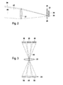
- FIG. 2 shows a detailed view of the overview drawing of the camera of the first embodiment according to FIG. 1 .
- FIG. 2 will be explained below how stray light from the same direction as the actual useful signal of the rain sensor function is hidden. Since parallel beams are focused from one direction to a point on the focal plane in which the image sensor 24 is approximately located, in the absence of the shutter 28 on the pixel area 38 reserved for rain sensor function, not only the light 30 coupled out of the disk hits as second optical radiation of the rain sensor, but also stray light 42 as the first optical radiation from the vehicle apron, which has the same direction.
- the image sensor 24 comprises a pixel area 36 for realizing at least one primary function.
- the stray light 44 is hidden by means of a mechanical shutter 28 in the first embodiment.
- the direction of the collimated light 30 (beam) of the rain sensor function is selected so that its angle of incidence just corresponds approximately to the maximum aperture angle of the camera and it falls on one of the lowest lines (the pixel area 38 reserved for the rain sensor function) of the image sensor 24.
- the passage location through the lens 22 is chosen as high as possible, but limited by a not shown field-limiting aperture.
- this Glaslid 26 is partially coated with an opaque layer on the top and / or the bottom depending on the required position of the aperture 28.
- the glass lid 26 is composed of two superimposed partial plates, so that the diaphragm layer can alternatively or additionally be applied to positions between the top and bottom of the glass lid 26.
- the image sensor 24 has a coating, wherein the coating is, for example, an angle-dependent filter which is designed such that interference light 42 (light from the interference direction) is suppressed and transmits light 30 of the useful direction.
- stray light 42 is alternatively or additionally taken into account mathematically.
- FIG. 3 shows an overview drawing with a view from above of the camera of the second embodiment, wherein only the changes compared to the first embodiment measures are listed and described below. Furthermore, the same reference numerals are used for the corresponding elements of the second compared to the first embodiment.
- a light sensor function is integrated in the camera in addition to the rain sensor function.
- light from at least one second direction is used in addition to the light from the detection range of the camera (light from the first direction).
- the light from the second direction is preferably from an area above the motor vehicle.
- a means for deflecting light from the at least one second direction to a second part of the image sensor 24 is used.
- the means for deflecting light are two mirrors 46 in this second exemplary embodiment.
- the light from the second direction is imaged by the mirrors 46 via the objective 22 onto two pixel areas 50 for the light sensor function, while the light for the rain sensor function is imaged by the decoupling element 20 via the objective 22 onto a pixel area 48 for the rain sensor function.
- the pixel areas 48, 50 of the light sensor function and the rain sensor function use the same lines of the image sensor 24.
- the lines used are subdivided, for example, into 3 pixel areas 48, 50.
- the middle pixel area 48 serves as a rain sensor, the outer two pixel areas 50 as light sensors.
- blocking by a mechanical shutter is to be provided immediately in front of the pixels in order to block stray light from the same direction.
- the interference immunity is performed in a variant of the embodiments described above by tuning the wavelength of the radiation source with the image sensor.
- the detectors pixels of the rain sensor functionality
- the detectors are adapted to the wavelength of the radiation source by optical bandpass filters, for example interference filters.
- an interference filter layer is applied directly to at least one pixel of the image sensor and / or attached in a second variant at another favorable location in the beam path.
- the interference immunity is increased by temporal synchronization between the radiation source and the image sensor.
- the radiation source is pulsed synchronously to the exposure phases of the image sensor. This achieves a higher signal-to-noise ratio.
- alternately images are taken with the radiation source switched on and off, so that the ambient light component, which is determined when the radiation source is switched off, is taken into account mathematically.
- a diverging beam path is collimated again before detection by the image sensor. This is done for example by a lens and / or a concave mirror.
- light with greater beam divergence is used to cover larger areas of the disk.
- additional optical elements such as deflection mirrors, and / or light-guiding elements, such as light guides.
- deflection mirrors and / or light-guiding elements, such as light guides.
- additional optical elements such as deflecting mirrors, and / or light-guiding elements, such as optical fibers, are used.
- the coupled-out light of the rain sensor function is coupled in bypassing the lens directly to the selected pixels of the image sensor.
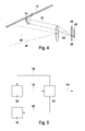
- FIG. 4 shows an overview drawing of the third, belonging to the prior art embodiment for the realization of a passive rain sensor function consisting of a parabolic mirror 51 as the first optical element and an image sensor 24, wherein only the measures compared to the first two embodiments listed measures and described below. Furthermore, the same reference numerals are used for the corresponding elements of the third compared to the first two embodiments.
- the moisture and / or wetting raindrops on the windshield 10 is recognized purely passive.
- the outside of the windshield 10 is detected with a matrix-shaped image sensor 24, the camera being focused on infinity and also providing a driver assistance function as a primary function, such as the night vision assistance function and / or the lane departure function.
- a parabolic mirror 51 is used, wherein the light 30 diverging from an object, for example a raindrop, is bundled by the parabolic mirror 51 in such a way that the light 30 then runs parallel and thus focused on a part of the image sensor 24 via the objective 22 imaged by the camera.
- the parabolic mirror 51 is designed and aligned such that its focal plane lies on the outside of the windshield 10. Furthermore, the parabolic mirror 51 simultaneously performs a deflection of the beam path of the light 30.
- a part of the image sensor 24 preferably an edge area, is used.
- the lower lines of the image sensor 24 are also used for the rain sensor function.
- the measuring range for the rain sensor function is an approximately rectangular area on the windscreen 10. Further shows FIG. 4 the optical axis 44 of the camera.
- a concave mirror which differs from the paraboloid shape, and / or a combination of at least one plane mirror and at least one lens used.
- FIG. 5 shows a block diagram of the above-described embodiments, consisting of an LED 16 as a radiation source, the image sensor 24 and an evaluation unit 52.
- the image sensor 24 transmits image signals via a signal line 56 to the evaluation unit 52.
- the evaluation unit 52 provides at least one parameter of the signal line 58 Image sensor 24 a. Furthermore, the evaluation unit 52 sets the LED 16 via the signal line 60.
- the evaluation unit 52 evaluates the image signals of the image sensor 24 and provides via the signal line 54 primary functions and / or the rain sensor function and / or the light sensor function and / or other functions subsequent systems available.
- the transmission on the signal lines 54, 56, 58, 60 takes place electrically and / or optically and / or by radio, preferably via a motor vehicle communication bus, such as the CAN bus.
- the transmission takes place on the signal lines 54, 56, 58, 60 by means of parallel LVDS lines (Low Voltage Differential Signaling lines) and / or Firewire and / or USB with preferably bandwidths above 10 Mbytes / s.
- Firewire or i.LINK is the IEEE 1394 technology.
- the Firewire interface enables the transmission of digital data at 400 Mbps, or preferably even higher data rates.
- the Universal Serial Bus (USB) is a fast bus system that allows multiple terminals to be connected to a single port.
- the evaluation unit 52 is designed such that it determines the moisture and / or wetting with water droplets of an external surface.
- Different intensity thresholds are defined to derive the wiping strategy. The ranges between these thresholds correspond to the various wiping modes of the wiper, such as interval, normal wiping operation, and / or fast wiping operation.
- the current intensity value is determined, for example, as the mean value and / or median of all used pixels of the rain sensor functionality.
- the wiping strategy is then determined.
- the histogram is evaluated over all used pixels and / or the histograms of specific pixel areas, and a refined moisture calculation is carried out via the formation of percentiles. Thus it can also be concluded from the distribution of the histogram on certain moisture conditions.
- the pixels of the rain sensor function are directly evaluated in a first variant and / or histograms of specific pixel regions are formed in a second variant.
- the evaluation strategy is adapted in a further variant depending on other information, such as navigation signals and / or weather data.
- a hardware sensor is integrated in the camera, which detects the fog on the inside of the windshield.
- portions of the image sensor, which serves to provide a primary function are also exploited.
- a polarizing filter is applied. This pixel area is used as a fog sensor, while the second pixel area is maintained as a rain sensor.
- the fitting sensor is taken into account that changes the beam path through the reflection on the inside of the disk against the rain sensor.
- small fitting particles have a polarizing effect, so that after reflection on a fogged surface linearly polarized light is produced.
- Light that overcomes the polarizing filter is therefore based predominantly on reflection at the fitting on the inside of the disk. Together with the different reflection location (inner side of the disc instead of outer side of the disc) there are two mechanisms for distinguishing between rain and fogging.
- the evaluation of the pixel areas of the fitting sensor is analogous to the evaluation described above in the rain sensor.
- the rain sensor functionality described above will be used to control the rear window wiper.
- the rain sensor functionality is preferably integrated in the reversing camera or in the front camera.
- a light sensor functionality and / or a fitting sensor functionality is integrated in the reversing camera.
- the camera comprises at least two or more than two image sensors, wherein in two image sensors the camera is embodied in a further variant as a stereo camera.
Landscapes
- Engineering & Computer Science (AREA)
- Multimedia (AREA)
- Mechanical Engineering (AREA)
- Physics & Mathematics (AREA)
- General Physics & Mathematics (AREA)
- Signal Processing (AREA)
- Automation & Control Theory (AREA)
- Theoretical Computer Science (AREA)
- Studio Devices (AREA)
- Investigating Or Analysing Materials By Optical Means (AREA)
- Traffic Control Systems (AREA)
Claims (13)
- Caméra (8) destinée à un véhicule automobile comportant au moins un capteur d'image (24) et un objectif (22) focalisé à l'infini (22), dans lequel la caméra (8) est conçue de manière à ce que le capteur d'image (24) détecte, par l'intermédiaire de l'objectif (22) focalisé à l'infini, un premier rayonnement optique (32) dans l'espace public de l'environnement du véhicule automobile, dans lequel la caméra (8) est conçue de manière à ce qu'un second rayonnement optique (30) différent du premier rayonnement optique (32) et sensiblement parallèle à celui-ci soit acheminé par l'intermédiaire de l'objectif (22) focalisé à l'infini vers une partie du capteur d'image (24), à ce qu'une image nette de celui-ci soit formée sur ladite partie du capteur d'image (24) et à ce qu'elle soit détecté par ladite partie dudit capteur d'image (24), dans lequel l'humidité et/ou la mouillabilité par des gouttes d'eau d'une surface externe d'une vitre (10) du véhicule automobile puisse être déterminée en fonction du second rayonnement optique (30) détecté, et la caméra (8) comporte au moins un premier élément optique (20), caractérisé en ce que
le premier élément optique (20) couple le second rayonnement optique (30) en sortie de la vitre (10). - Caméra selon la revendication 1, caractérisée en ce que la caméra (8) comporte au moins une source de rayonnement (16) et/ou au moins un second élément optique (18) et/ou au moins une lentille (22).
- Caméra selon l'une quelconque des revendications précédentes, caractérisée en ce que le premier élément optique (20) achemine le second rayonnement optique (30), de préférence par l'intermédiaire d'une lentille (22), vers ladite partie du capteur d'image (24).
- Caméra selon l'une quelconque des revendications précédentes, caractérisée en ce que le premier élément optique collimate et/ou dévie le second rayonnement optique.
- Caméra selon l'une quelconque des revendications précédentes lorsqu'elles dépendent de la revendication 2, caractérisée en ce que la source de rayonnement (16) génère le second rayonnement optique (30), dans lequel le second rayonnement optique (30) est collimaté et/ou est collimaté après avoir été généré.
- Caméra selon l'une quelconque des revendications précédentes lorsqu'elles dépendent de la revendication 2, caractérisée en ce que le second élément optique (18) injecte le second rayonnement optique (30) sur une surface interne de la vitre (10) de manière à ce que le second rayonnement optique (30) soit réfléchi au moins une fois sur la surface externe (12, 14) avant sa sortie de la surface interne de la vitre (10).
- Caméra selon l'une quelconque des revendications 2 à 6, caractérisée en ce que la source de rayonnement (16) et/ou le premier élément optique (20) et/ou le second rayonnement optique (18) sont intégrés à un diaphragme anti-lumière parasite (34) de la caméra et/ou d'un boîtier de la caméra.
- Caméra selon l'une quelconque des revendications précédentes, caractérisée en ce que la caméra (8) comprend au moins un diaphragme, dans lequel le diaphragme est conçu de manière à ce que le premier rayonnement optique (32) soit occulté par ladite partie du capteur d'image tandis que le second rayonnement optique (30) est détecté par ladite seconde partie du capteur d'image (24).
- Caméra selon la revendication 8, caractérisée en ce que le masque (34) est intégré à un capot de protection du capteur d'image et/ou en ce que le diaphragme est un revêtement du capteur d'image.
- Caméra selon l'une quelconque des revendications précédentes, caractérisée en ce que la caméra (8) comprend au moins un filtre optique, dans lequel le filtre optique est de préférence conçu de manière à ce que le second rayonnement optique (30) ne soit détecté que par ladite partie du capteur d'image.
- Caméra selon l'une quelconque des revendications précédentes, caractérisée en ce que la caméra (8) comprend une unité d'évaluation (52) qui fournit au moins une fonction d'aide à la conduite en fonction du premier rayonnement optique (32), dans lequel la fonction d'aide à la conduite est notamment une fonction d'aide à la vision nocturne et/ou une fonction d'alerte à la sortie de route et/ou une fonction de détection de panneaux routiers et/ou une fonction d'aide au recul.
- Caméra selon l'une quelconque des revendications précédentes, caractérisée en ce que la caméra (8) est conçue de manière à ce que- au moins un paramètre d'éclairement du capteur d'image soit réglé en fonction du second rayonnement optique et/ou- l'intensité et/ou l'évolution temporelle du second rayonnement optique soit réglée et/ou- le capteur d'image et le second rayonnement optique soient synchronisés.
- Caméra selon l'une quelconque des revendications précédentes, caractérisée en ce que la caméra (8) comporte des moyens destinés à déterminer la luminosité dans l'environnement du véhicule automobile et/ou en ce que la caméra comporte des moyens destinés à déterminer la présence de buée sur une surface interne de la vitre.
Applications Claiming Priority (2)
| Application Number | Priority Date | Filing Date | Title |
|---|---|---|---|
| DE102004015040A DE102004015040A1 (de) | 2004-03-26 | 2004-03-26 | Kamera in einem Kraftfahrzeug |
| DE102004015040 | 2004-03-26 |
Publications (3)
| Publication Number | Publication Date |
|---|---|
| EP1580092A2 EP1580092A2 (fr) | 2005-09-28 |
| EP1580092A3 EP1580092A3 (fr) | 2006-02-08 |
| EP1580092B1 true EP1580092B1 (fr) | 2015-09-23 |
Family
ID=34854084
Family Applications (1)
| Application Number | Title | Priority Date | Filing Date |
|---|---|---|---|
| EP05100746.6A Ceased EP1580092B1 (fr) | 2004-03-26 | 2005-02-03 | Caméra pour un véhicule automobile |
Country Status (2)
| Country | Link |
|---|---|
| EP (1) | EP1580092B1 (fr) |
| DE (1) | DE102004015040A1 (fr) |
Cited By (3)
| Publication number | Priority date | Publication date | Assignee | Title |
|---|---|---|---|---|
| DE102021109171A1 (de) | 2021-04-13 | 2022-10-13 | Valeo Schalter Und Sensoren Gmbh | Regensensorsystem und fahrzeug |
| DE102022123456A1 (de) | 2022-09-14 | 2024-03-14 | Valeo Schalter Und Sensoren Gmbh | Einrichtung für ein fahrzeug |
| WO2026073785A1 (fr) * | 2024-10-02 | 2026-04-09 | Saint-Gobain Sekurit France | Agencement de séchage de vitre de véhicule |
Families Citing this family (70)
| Publication number | Priority date | Publication date | Assignee | Title |
|---|---|---|---|---|
| DE102004037871B4 (de) * | 2004-08-04 | 2006-10-12 | Siemens Ag | Optisches Modul für ein den Außenvorraum in Fahrtrichtung eines Kraftfahrzeuges erfassendes Assistenzsystem |
| DE102005058718B4 (de) * | 2005-12-08 | 2020-06-04 | Conti Temic Microelectronic Gmbh | Sensorsystem zur Umgebungserfassung und zur Regendetektion |
| DE102006008274B4 (de) * | 2006-02-22 | 2021-11-25 | Continental Automotive Gmbh | Kraftfahrzeug mit einer optischen Erfassungsvorrichtung und Verfahren zum Betreiben eines Kraftfahrzeugs |
| DE102006010671A1 (de) * | 2006-03-08 | 2007-09-13 | Leopold Kostal Gmbh & Co. Kg | Kameraanordnung für ein Kraftfahrzeug |
| FR2901218B1 (fr) | 2006-05-22 | 2009-02-13 | Valeo Vision Sa | Procede de detection de pluie sur un parebrise |
| DE102006045916B4 (de) * | 2006-09-28 | 2010-03-18 | Pepperl + Fuchs Gmbh | Lichttaster oder Lichtschranke zum Nachweis von Objekten und Testverfahren für den Verschmutzungsgrad eines Lichttasters oder einer Lichtschranke |
| EP1923695A1 (fr) | 2006-11-20 | 2008-05-21 | Delphi Technologies, Inc. | Dispositif destiné à l'enregistrement de l'humidité sur un disque |
| DE102007049877A1 (de) * | 2007-10-18 | 2009-04-23 | Valeo Schalter Und Sensoren Gmbh | Sensormodul und Betriebsverfahren hierfür |
| ATE471254T1 (de) | 2007-11-21 | 2010-07-15 | Delphi Tech Inc | Optisches modul |
| DE102008033204A1 (de) * | 2008-07-15 | 2010-02-04 | Trw Automotive Electronics & Components Gmbh | Optischer Sensor |
| DE102008039606A1 (de) | 2008-08-25 | 2010-03-04 | GM Global Technology Operations, Inc., Detroit | Kraftfahrzeug mit einem Abstandssensor und einem Bilderfassungssystem |
| DE102008044003A1 (de) | 2008-11-24 | 2010-05-27 | Robert Bosch Gmbh | Kameramodul mit Mehrfachfunktion |
| DE102008062154B4 (de) * | 2008-12-16 | 2021-08-26 | Volkswagen Ag | Steuerung eines Kamera-Systems eines Kraftfahrzeugs und Fahrerassistenzsystem |
| DE102008062977A1 (de) * | 2008-12-23 | 2010-06-24 | Adc Automotive Distance Control Systems Gmbh | Optisches Modul mit multifokaler Optik zur Erfassung von Fern- und Nahbereich in einem Bild |
| DE102009000003A1 (de) * | 2009-01-02 | 2010-07-08 | Robert Bosch Gmbh | Kameraanordnung zur Erfassung eines Scheibenzustandes einer Fahrzeugscheibe |
| DE102009000004A1 (de) * | 2009-01-02 | 2010-07-08 | Robert Bosch Gmbh | Kameraanordnung für ein Kraftfahrzeug und Kraftfahrzeug mit einer Kameraanordnung |
| DE102009000005A1 (de) † | 2009-01-02 | 2010-07-08 | Robert Bosch Gmbh | Kameraanordnung und Verfahren zur Erfassung einer Fahrzeugumgebung |
| DE102009018515A1 (de) * | 2009-04-23 | 2010-11-11 | Bury Sp.Z.O.O | Kameravorrichtung zur Verwendung in einem Kraftfahrzeug |
| WO2011003381A1 (fr) * | 2009-07-06 | 2011-01-13 | Conti Temic Microelectronic Gmbh | Module optique destiné à la focalisation simultanée de deux champs de vision |
| DE102009027512A1 (de) | 2009-07-08 | 2011-01-20 | Robert Bosch Gmbh | Vorrichtung zur Erfassung von Bilddaten |
| DE102009048493A1 (de) | 2009-09-25 | 2011-04-07 | Valeo Schalter Und Sensoren Gmbh | Fahrerassistenzsystem für ein Fahrzeug, Fahrzeug mit einem Fahrerassistenzsystem und Verfahren zum Unterstützen eines Fahrers beim Führen eines Fahrzeugs |
| FR2957160B1 (fr) * | 2010-03-05 | 2012-05-11 | Valeo Vision | Camera agencee pour pouvoir etre embarquee sur un vehicule |
| DE102010003666B4 (de) | 2010-04-07 | 2019-07-04 | Robert Bosch Gmbh | Kamera für ein Fahrzeug und Anordnung aus einer Kamera und einem Kamerahalter |
| DE102010015214A1 (de) * | 2010-04-16 | 2011-10-20 | Conti Temic Microelectronic Gmbh | Verfahren und Vorrichtung zur Fahrerunterstützung beim Fahren eines Fahrzeugs durch Detektion von wetterbedingten Sichteinschränkungen |
| DE102010028347A1 (de) | 2010-04-29 | 2011-11-03 | Robert Bosch Gmbh | Sensoranordnung an einem Kraftfahrzeug |
| DE102010023532A1 (de) * | 2010-06-11 | 2011-12-15 | Conti Temic Microelectronic Gmbh | Kamerasystem für Fahrzeuganwendungen |
| DE102010023531A1 (de) * | 2010-06-11 | 2011-12-15 | Conti Temic Microelectronic Gmbh | Optisches Element zur multifokalen Abbildung in einer Kamera für Fahrzeuganwendungen |
| DE102010023593A1 (de) * | 2010-06-12 | 2011-12-15 | Conti Temic Microelectronic Gmbh | Optische Vorrichtung mit einem bifokalen optischen Element und einem Spiegelelement |
| DE102010023591A1 (de) * | 2010-06-12 | 2011-12-15 | Conti Temic Microelectronic Gmbh | Stereokamerasystem |
| DE102010043479B4 (de) | 2010-11-05 | 2019-03-07 | Robert Bosch Gmbh | Kameraanordnung und Verfahren zum Betreiben einer Kameraanordnung für ein Kraftfahrzeug |
| CN103221805B (zh) * | 2010-11-30 | 2016-10-12 | 康蒂特米克微电子有限公司 | 借助于摄像机和照明装置检测窗玻璃上的雨滴 |
| DE102011003803A1 (de) * | 2011-02-08 | 2012-08-09 | Robert Bosch Gmbh | Verfahren und Vorrichtung zur Bestimmung einer Klarsichtigkeit einer Scheibe eines Fahrzeugs |
| DE102011004284A1 (de) * | 2011-02-17 | 2012-08-23 | Robert Bosch Gmbh | Verfahren zur Herstellung einer optischen Vorrichtung sowie optische Vorrichtung |
| DE102011017355B4 (de) * | 2011-04-16 | 2022-08-11 | Continental Autonomous Mobility Germany GmbH | Multifokales Abbildungssystem mit optischen Filtern |
| DE102011017356A1 (de) * | 2011-04-16 | 2012-10-18 | Conti Temic Microelectronic Gmbh | Optisches Modul zur bi- oder multifokalen Abbildung |
| DE102011076133A1 (de) * | 2011-05-19 | 2012-11-22 | Robert Bosch Gmbh | Prüfvorrichtung für eine Kamera sowie ein Verfahren zur Prüfung einer Kamera |
| DE102011103340A1 (de) * | 2011-06-03 | 2012-12-06 | Continental Automotive Gmbh | Vorrichtung mit optischem Sensorsystem und Antibeschlaglösung |
| DE102011103302A1 (de) * | 2011-06-03 | 2012-12-06 | Conti Temic Microelectronic Gmbh | Kamerasystem für ein Fahrzeug |
| JP2013029451A (ja) * | 2011-07-29 | 2013-02-07 | Ricoh Co Ltd | 付着物検出装置及び付着物検出方法 |
| DE102011112212A1 (de) * | 2011-09-02 | 2013-03-07 | Conti Temic Microelectronic Gmbh | Vorrichtung und Verfahren zur Feuchtigkeitserfassung auf einer Scheibe |
| DE102011113810A1 (de) * | 2011-09-20 | 2013-03-21 | Conti Temic Microelectronic Gmbh | Vorrichtung zur Feuchtigkeitserkennung |
| DE102011083232B4 (de) * | 2011-09-22 | 2021-02-11 | Robert Bosch Gmbh | Bilderfassungsvorrichtung für ein Fahrzeug |
| DE102011055928A1 (de) * | 2011-12-01 | 2013-06-06 | Conti Temic Microelectronic Gmbh | Optische Vorrichtung mit multifokaler Abbildung |
| DE102011056051A1 (de) | 2011-12-05 | 2013-06-06 | Conti Temic Microelectronic Gmbh | Verfahren zur Auswertung von Bilddaten einer Fahrzeugkamera unter Berücksichtigung von Informationen über Regen |
| DE102011056690A1 (de) | 2011-12-20 | 2013-06-20 | Continental Automotive Gmbh | Verfahren und Vorrichtung zur Ermittlung von Feuchtigkeit auf einer Fahrzeugscheibe |
| DE102012200200B4 (de) | 2012-01-09 | 2020-09-17 | Robert Bosch Gmbh | Kamerasystem, insbesondere für ein Fahrzeug, sowie ein Fahrzeug |
| DE202012003277U1 (de) | 2012-03-22 | 2012-07-11 | Iris-Gmbh Infrared & Intelligent Sensors | Erkennung von Signalstörungen eines optischen Sensors hervorgerufen durch Beschädigungen oder Verdeckungen |
| DE102012103873A1 (de) * | 2012-05-03 | 2013-11-21 | Conti Temic Microelectronic Gmbh | Detektion von Regentropfen auf einer Scheibe mittels einer Kamera und Beleuchtung |
| DE102012106030A1 (de) * | 2012-07-05 | 2014-05-22 | Continental Automotive Gmbh | Kamerasystem zur Erkennung des Zustands einer Fahrzeugscheibe |
| DE102013100292A1 (de) | 2013-01-11 | 2014-07-24 | Conti Temic Microelectronic Gmbh | Beleuchtung zur Detektion von Regentropfen auf einer Scheibe mittels einer Kamera |
| KR102081747B1 (ko) * | 2012-08-06 | 2020-02-26 | 콘티 테믹 마이크로일렉트로닉 게엠베하 | 카메라 및 조명에 의한 유리창의 우적 감지 |
| DE102012108316A1 (de) * | 2012-08-06 | 2014-02-06 | Conti Temic Microelectronic Gmbh | Detektion von Regentropfen auf einer Scheibe mittels einer Kamera und Beleuchtung |
| DE102013000751B4 (de) * | 2013-01-17 | 2024-02-29 | HELLA GmbH & Co. KGaA | Sensorvorrichtung zum Erfassen von Feuchtigkeit auf einer Scheibe |
| US20150124094A1 (en) * | 2013-11-05 | 2015-05-07 | Delphi Technologies, Inc. | Multiple imager vehicle optical sensor system |
| DE102013225155A1 (de) | 2013-12-06 | 2015-06-11 | Conti Temic Microelectronic Gmbh | Beleuchtung zur Detektion von Regentropfen auf einer Scheibe mittels einer Kamera |
| DE102013225156A1 (de) | 2013-12-06 | 2015-06-11 | Conti Temic Microelectronic Gmbh | Beleuchtung zur Detektion von Regentropfen auf einer Scheibe mittels einer Kamera |
| DE102014214710B4 (de) * | 2014-07-25 | 2022-02-17 | Conti Temic Microelectronic Gmbh | Regendetektionsvorrichtung |
| EP2977275B1 (fr) * | 2014-07-25 | 2017-04-26 | Conti Temic microelectronic GmbH | Dispositif de détection de pluie |
| DE102014217749B4 (de) * | 2014-09-04 | 2024-06-13 | Continental Autonomous Mobility Germany GmbH | Streulichtblende, Fahrerassistenzsystem und Verfahren |
| US9506803B2 (en) * | 2014-09-17 | 2016-11-29 | Delphi Technologies, Inc. | Vehicle optical sensor system |
| DE102014220652A1 (de) * | 2014-10-13 | 2016-04-14 | Continental Automotive Gmbh | Fahrzeugscheibe mit einer Scheibenheizung und Heiz- und Sensoreinheit für ein Fahrzeug |
| US9245333B1 (en) | 2014-12-10 | 2016-01-26 | Semiconductor Components Industries, Llc | Systems and methods for detecting obstructions within the field-of-view of an image sensor |
| US9781361B2 (en) * | 2015-09-01 | 2017-10-03 | Delphi Technologies, Inc. | Integrated camera, ambient light detection, and rain sensor assembly |
| EP3634807B1 (fr) * | 2017-06-26 | 2021-08-04 | Gentex Corporation | Étalonnage dynamique de propriétés optiques d'un élément de gradation |
| CN108540730B (zh) * | 2018-03-29 | 2020-12-15 | 台州市吉吉知识产权运营有限公司 | 一种适用于物联网设备拍摄的补光方法及系统 |
| CN108528354B (zh) * | 2018-06-04 | 2023-08-08 | 威马智慧出行科技(上海)有限公司 | 车载摄像头支架及包括其的汽车 |
| CN110435665B (zh) * | 2019-08-14 | 2024-07-02 | 东风汽车有限公司 | 一种驾驶员检测装置及汽车 |
| DE102019213997A1 (de) * | 2019-09-13 | 2021-03-18 | Volkswagen Aktiengesellschaft | Kamerasystem für ein Fahrzeug |
| CN113677073B (zh) * | 2021-08-11 | 2024-03-22 | 董全喜 | 一种应用于车辆的分区感光装置 |
| DE102022200542A1 (de) | 2022-01-18 | 2023-07-20 | Robert Bosch Gesellschaft mit beschränkter Haftung | Verfahren zum Ableiten zumindest einer Information aus Bildern einer Stereokamera |
Family Cites Families (8)
| Publication number | Priority date | Publication date | Assignee | Title |
|---|---|---|---|---|
| DE4032927A1 (de) | 1990-10-17 | 1992-04-30 | Bosch Gmbh Robert | Vorrichtung zur verbesserung der sichtverhaeltnisse in einem kraftfahrzeug |
| WO1997029926A1 (fr) | 1996-02-13 | 1997-08-21 | Marquardt Gmbh | Detecteur optique |
| JPH1090188A (ja) | 1996-09-13 | 1998-04-10 | Mitsuba Corp | 画像認識装置 |
| DE19749331A1 (de) | 1997-11-07 | 1999-05-20 | Kostal Leopold Gmbh & Co Kg | Verfahren zum Detektieren von auf einer Windschutzscheibe befindlichen Objekten sowie Vorrichtung |
| JP4277308B2 (ja) * | 1999-11-25 | 2009-06-10 | 日本精機株式会社 | 雨滴検出装置 |
| US6596978B2 (en) | 2001-06-28 | 2003-07-22 | Valeo Electrical Systems, Inc. | Stereo imaging rain sensor |
| GB0216483D0 (en) * | 2002-07-16 | 2002-08-21 | Trw Ltd | Vehicle window cleaning apparatus and method |
| JP4326999B2 (ja) * | 2003-08-12 | 2009-09-09 | 株式会社日立製作所 | 画像処理システム |
-
2004
- 2004-03-26 DE DE102004015040A patent/DE102004015040A1/de not_active Ceased
-
2005
- 2005-02-03 EP EP05100746.6A patent/EP1580092B1/fr not_active Ceased
Cited By (4)
| Publication number | Priority date | Publication date | Assignee | Title |
|---|---|---|---|---|
| DE102021109171A1 (de) | 2021-04-13 | 2022-10-13 | Valeo Schalter Und Sensoren Gmbh | Regensensorsystem und fahrzeug |
| WO2022219011A1 (fr) | 2021-04-13 | 2022-10-20 | Valeo Schalter Und Sensoren Gmbh | Système de détecteur de pluie et véhicule |
| DE102022123456A1 (de) | 2022-09-14 | 2024-03-14 | Valeo Schalter Und Sensoren Gmbh | Einrichtung für ein fahrzeug |
| WO2026073785A1 (fr) * | 2024-10-02 | 2026-04-09 | Saint-Gobain Sekurit France | Agencement de séchage de vitre de véhicule |
Also Published As
| Publication number | Publication date |
|---|---|
| EP1580092A3 (fr) | 2006-02-08 |
| EP1580092A2 (fr) | 2005-09-28 |
| DE102004015040A1 (de) | 2005-10-13 |
Similar Documents
| Publication | Publication Date | Title |
|---|---|---|
| EP1580092A2 (fr) | Caméra pour un véhicule automobile | |
| DE60305124T2 (de) | Multifunktionales integriertes optisches System mit einer CMOS oder CCD Matrix | |
| DE60214593T2 (de) | Stereoabbildung mit einem bildsensor verwendender feuchtigkeitssensor | |
| DE102004037871B4 (de) | Optisches Modul für ein den Außenvorraum in Fahrtrichtung eines Kraftfahrzeuges erfassendes Assistenzsystem | |
| EP1706773B1 (fr) | Systeme de vision nocturne a filtre optique partiel pour des vehicules automobiles | |
| EP2715446B1 (fr) | Système de caméra pour un véhicule | |
| EP1275981B1 (fr) | Dispositif d'amélioration de la visibilité dans des véhicules | |
| DE102012200200B4 (de) | Kamerasystem, insbesondere für ein Fahrzeug, sowie ein Fahrzeug | |
| DE10126492B4 (de) | Verfahren zur Verbesserung der Sicht in Fahrzeugen | |
| EP2384292B1 (fr) | Système de caméra pour un véhicule automobile et véhicule automobile comprenant un système de caméra | |
| DE102013210887B4 (de) | Optische Sensoranordnung für ein Fahrzeug und Fahrzeug mit einer derartigen Sensoranordnung | |
| EP2646802A1 (fr) | Détection de gouttes de pluie sur une vitre au moyen d'une caméra et d'un éclairage | |
| DE60206369T2 (de) | Belichtungs- regensensor- erleuchtungs- positionierungsanlage | |
| DE102008062977A1 (de) | Optisches Modul mit multifokaler Optik zur Erfassung von Fern- und Nahbereich in einem Bild | |
| DE19909986C2 (de) | Optoelektronische Überwachungseinrichtung für ein Kraftfahrzeug | |
| DE10323560B4 (de) | Kamera und Vorrichtung zur Ermittlung der Helligkeit der Umgebung eines Kraftfahrzeuges | |
| DE102017222614A1 (de) | Vorrichtung zur Umgebungserfassung sowie Verfahren zu dessen Betrieb | |
| DE10138361A1 (de) | Verfahren zur Verbessung der Sicht in Fahrzeugen | |
| DE102006008274B4 (de) | Kraftfahrzeug mit einer optischen Erfassungsvorrichtung und Verfahren zum Betreiben eines Kraftfahrzeugs | |
| EP1503224A2 (fr) | Dispositif pour améliorer la visibilité dans véhicules | |
| DE102010023593A1 (de) | Optische Vorrichtung mit einem bifokalen optischen Element und einem Spiegelelement | |
| DE102017120653A1 (de) | Head-Up-Display-Vorrichtung mit einer Detektionsvorrichtung | |
| WO2013091619A1 (fr) | Procédé et dispositif pour détecter de l'humidité sur une vitre de véhicule | |
| DE102011017355B4 (de) | Multifokales Abbildungssystem mit optischen Filtern | |
| DE102012111199A1 (de) | Optische Vorrichtung mit multifokaler Bilderfassung |
Legal Events
| Date | Code | Title | Description |
|---|---|---|---|
| PUAI | Public reference made under article 153(3) epc to a published international application that has entered the european phase |
Free format text: ORIGINAL CODE: 0009012 |
|
| AK | Designated contracting states |
Kind code of ref document: A2 Designated state(s): AT BE BG CH CY CZ DE DK EE ES FI FR GB GR HU IE IS IT LI LT LU MC NL PL PT RO SE SI SK TR |
|
| AX | Request for extension of the european patent |
Extension state: AL BA HR LV MK YU |
|
| PUAL | Search report despatched |
Free format text: ORIGINAL CODE: 0009013 |
|
| AK | Designated contracting states |
Kind code of ref document: A3 Designated state(s): AT BE BG CH CY CZ DE DK EE ES FI FR GB GR HU IE IS IT LI LT LU MC NL PL PT RO SE SI SK TR |
|
| AX | Request for extension of the european patent |
Extension state: AL BA HR LV MK YU |
|
| 17P | Request for examination filed |
Effective date: 20060808 |
|
| 17Q | First examination report despatched |
Effective date: 20060908 |
|
| AKX | Designation fees paid |
Designated state(s): DE FR GB IT SE |
|
| GRAP | Despatch of communication of intention to grant a patent |
Free format text: ORIGINAL CODE: EPIDOSNIGR1 |
|
| INTG | Intention to grant announced |
Effective date: 20150630 |
|
| GRAS | Grant fee paid |
Free format text: ORIGINAL CODE: EPIDOSNIGR3 |
|
| GRAA | (expected) grant |
Free format text: ORIGINAL CODE: 0009210 |
|
| AK | Designated contracting states |
Kind code of ref document: B1 Designated state(s): DE FR GB IT SE |
|
| REG | Reference to a national code |
Ref country code: GB Ref legal event code: FG4D Free format text: NOT ENGLISH |
|
| REG | Reference to a national code |
Ref country code: DE Ref legal event code: R096 Ref document number: 502005014938 Country of ref document: DE |
|
| REG | Reference to a national code |
Ref country code: FR Ref legal event code: PLFP Year of fee payment: 12 |
|
| PG25 | Lapsed in a contracting state [announced via postgrant information from national office to epo] |
Ref country code: SE Free format text: LAPSE BECAUSE OF FAILURE TO SUBMIT A TRANSLATION OF THE DESCRIPTION OR TO PAY THE FEE WITHIN THE PRESCRIBED TIME-LIMIT Effective date: 20150923 |
|
| PG25 | Lapsed in a contracting state [announced via postgrant information from national office to epo] |
Ref country code: IT Free format text: LAPSE BECAUSE OF FAILURE TO SUBMIT A TRANSLATION OF THE DESCRIPTION OR TO PAY THE FEE WITHIN THE PRESCRIBED TIME-LIMIT Effective date: 20150923 |
|
| REG | Reference to a national code |
Ref country code: DE Ref legal event code: R097 Ref document number: 502005014938 Country of ref document: DE |
|
| PLBE | No opposition filed within time limit |
Free format text: ORIGINAL CODE: 0009261 |
|
| STAA | Information on the status of an ep patent application or granted ep patent |
Free format text: STATUS: NO OPPOSITION FILED WITHIN TIME LIMIT |
|
| 26N | No opposition filed |
Effective date: 20160624 |
|
| REG | Reference to a national code |
Ref country code: FR Ref legal event code: PLFP Year of fee payment: 13 |
|
| REG | Reference to a national code |
Ref country code: FR Ref legal event code: PLFP Year of fee payment: 14 |
|
| PGFP | Annual fee paid to national office [announced via postgrant information from national office to epo] |
Ref country code: GB Payment date: 20200225 Year of fee payment: 16 |
|
| PGFP | Annual fee paid to national office [announced via postgrant information from national office to epo] |
Ref country code: FR Payment date: 20200220 Year of fee payment: 16 |
|
| PGFP | Annual fee paid to national office [announced via postgrant information from national office to epo] |
Ref country code: DE Payment date: 20200421 Year of fee payment: 16 |
|
| REG | Reference to a national code |
Ref country code: DE Ref legal event code: R119 Ref document number: 502005014938 Country of ref document: DE |
|
| GBPC | Gb: european patent ceased through non-payment of renewal fee |
Effective date: 20210203 |
|
| PG25 | Lapsed in a contracting state [announced via postgrant information from national office to epo] |
Ref country code: DE Free format text: LAPSE BECAUSE OF NON-PAYMENT OF DUE FEES Effective date: 20210901 Ref country code: FR Free format text: LAPSE BECAUSE OF NON-PAYMENT OF DUE FEES Effective date: 20210228 Ref country code: GB Free format text: LAPSE BECAUSE OF NON-PAYMENT OF DUE FEES Effective date: 20210203 |