EP1706773B1 - Systeme de vision nocturne a filtre optique partiel pour des vehicules automobiles - Google Patents
Systeme de vision nocturne a filtre optique partiel pour des vehicules automobiles Download PDFInfo
- Publication number
- EP1706773B1 EP1706773B1 EP04820035A EP04820035A EP1706773B1 EP 1706773 B1 EP1706773 B1 EP 1706773B1 EP 04820035 A EP04820035 A EP 04820035A EP 04820035 A EP04820035 A EP 04820035A EP 1706773 B1 EP1706773 B1 EP 1706773B1
- Authority
- EP
- European Patent Office
- Prior art keywords
- night vision
- image sensor
- vision system
- radiation
- filter
- Prior art date
- Legal status (The legal status is an assumption and is not a legal conclusion. Google has not performed a legal analysis and makes no representation as to the accuracy of the status listed.)
- Expired - Lifetime
Links
- 230000004297 night vision Effects 0.000 title claims description 39
- 230000003287 optical effect Effects 0.000 title description 13
- 230000005855 radiation Effects 0.000 claims description 31
- 230000001419 dependent effect Effects 0.000 claims description 17
- 230000005540 biological transmission Effects 0.000 claims description 10
- 238000000576 coating method Methods 0.000 claims description 9
- 239000011248 coating agent Substances 0.000 claims description 8
- 230000002238 attenuated effect Effects 0.000 claims description 4
- 230000001629 suppression Effects 0.000 claims description 3
- 230000000694 effects Effects 0.000 claims description 2
- 230000005670 electromagnetic radiation Effects 0.000 claims description 2
- 239000011521 glass Substances 0.000 claims description 2
- 238000001228 spectrum Methods 0.000 claims description 2
- 230000001681 protective effect Effects 0.000 claims 1
- 230000003595 spectral effect Effects 0.000 description 8
- 238000005286 illumination Methods 0.000 description 5
- 230000006872 improvement Effects 0.000 description 5
- 238000010586 diagram Methods 0.000 description 4
- 238000013461 design Methods 0.000 description 3
- 238000001514 detection method Methods 0.000 description 3
- 230000010287 polarization Effects 0.000 description 3
- 238000012805 post-processing Methods 0.000 description 3
- 238000012545 processing Methods 0.000 description 3
- 238000002834 transmittance Methods 0.000 description 3
- 238000010521 absorption reaction Methods 0.000 description 2
- 230000000903 blocking effect Effects 0.000 description 2
- 238000011161 development Methods 0.000 description 2
- 230000018109 developmental process Effects 0.000 description 2
- 229910052736 halogen Inorganic materials 0.000 description 2
- 150000002367 halogens Chemical class 0.000 description 2
- 238000003384 imaging method Methods 0.000 description 2
- 239000000463 material Substances 0.000 description 2
- 238000000034 method Methods 0.000 description 2
- 230000035945 sensitivity Effects 0.000 description 2
- 238000000926 separation method Methods 0.000 description 2
- 230000004913 activation Effects 0.000 description 1
- 230000006978 adaptation Effects 0.000 description 1
- 239000010426 asphalt Substances 0.000 description 1
- 230000009286 beneficial effect Effects 0.000 description 1
- 230000000295 complement effect Effects 0.000 description 1
- 239000006059 cover glass Substances 0.000 description 1
- 238000013016 damping Methods 0.000 description 1
- 238000005516 engineering process Methods 0.000 description 1
- 230000004438 eyesight Effects 0.000 description 1
- 210000003608 fece Anatomy 0.000 description 1
- 238000002329 infrared spectrum Methods 0.000 description 1
- 230000002452 interceptive effect Effects 0.000 description 1
- 230000035699 permeability Effects 0.000 description 1
- 230000008569 process Effects 0.000 description 1
- 239000004065 semiconductor Substances 0.000 description 1
- 238000001429 visible spectrum Methods 0.000 description 1
- 238000012800 visualization Methods 0.000 description 1
Images

Classifications
-
- B—PERFORMING OPERATIONS; TRANSPORTING
- B60—VEHICLES IN GENERAL
- B60R—VEHICLES, VEHICLE FITTINGS, OR VEHICLE PARTS, NOT OTHERWISE PROVIDED FOR
- B60R1/00—Optical viewing arrangements; Real-time viewing arrangements for drivers or passengers using optical image capturing systems, e.g. cameras or video systems specially adapted for use in or on vehicles
- B60R1/20—Real-time viewing arrangements for drivers or passengers using optical image capturing systems, e.g. cameras or video systems specially adapted for use in or on vehicles
- B60R1/30—Real-time viewing arrangements for drivers or passengers using optical image capturing systems, e.g. cameras or video systems specially adapted for use in or on vehicles providing vision in the non-visible spectrum, e.g. night or infrared vision
-
- B—PERFORMING OPERATIONS; TRANSPORTING
- B60—VEHICLES IN GENERAL
- B60R—VEHICLES, VEHICLE FITTINGS, OR VEHICLE PARTS, NOT OTHERWISE PROVIDED FOR
- B60R1/00—Optical viewing arrangements; Real-time viewing arrangements for drivers or passengers using optical image capturing systems, e.g. cameras or video systems specially adapted for use in or on vehicles
- B60R1/20—Real-time viewing arrangements for drivers or passengers using optical image capturing systems, e.g. cameras or video systems specially adapted for use in or on vehicles
- B60R1/22—Real-time viewing arrangements for drivers or passengers using optical image capturing systems, e.g. cameras or video systems specially adapted for use in or on vehicles for viewing an area outside the vehicle, e.g. the exterior of the vehicle
- B60R1/23—Real-time viewing arrangements for drivers or passengers using optical image capturing systems, e.g. cameras or video systems specially adapted for use in or on vehicles for viewing an area outside the vehicle, e.g. the exterior of the vehicle with a predetermined field of view
- B60R1/24—Real-time viewing arrangements for drivers or passengers using optical image capturing systems, e.g. cameras or video systems specially adapted for use in or on vehicles for viewing an area outside the vehicle, e.g. the exterior of the vehicle with a predetermined field of view in front of the vehicle
-
- G—PHYSICS
- G01—MEASURING; TESTING
- G01S—RADIO DIRECTION-FINDING; RADIO NAVIGATION; DETERMINING DISTANCE OR VELOCITY BY USE OF RADIO WAVES; LOCATING OR PRESENCE-DETECTING BY USE OF THE REFLECTION OR RERADIATION OF RADIO WAVES; ANALOGOUS ARRANGEMENTS USING OTHER WAVES
- G01S17/00—Systems using the reflection or reradiation of electromagnetic waves other than radio waves, e.g. lidar systems
- G01S17/88—Lidar systems specially adapted for specific applications
- G01S17/89—Lidar systems specially adapted for specific applications for mapping or imaging
-
- G—PHYSICS
- G01—MEASURING; TESTING
- G01S—RADIO DIRECTION-FINDING; RADIO NAVIGATION; DETERMINING DISTANCE OR VELOCITY BY USE OF RADIO WAVES; LOCATING OR PRESENCE-DETECTING BY USE OF THE REFLECTION OR RERADIATION OF RADIO WAVES; ANALOGOUS ARRANGEMENTS USING OTHER WAVES
- G01S17/00—Systems using the reflection or reradiation of electromagnetic waves other than radio waves, e.g. lidar systems
- G01S17/88—Lidar systems specially adapted for specific applications
- G01S17/93—Lidar systems specially adapted for specific applications for anti-collision purposes
- G01S17/931—Lidar systems specially adapted for specific applications for anti-collision purposes of land vehicles
-
- G—PHYSICS
- G01—MEASURING; TESTING
- G01S—RADIO DIRECTION-FINDING; RADIO NAVIGATION; DETERMINING DISTANCE OR VELOCITY BY USE OF RADIO WAVES; LOCATING OR PRESENCE-DETECTING BY USE OF THE REFLECTION OR RERADIATION OF RADIO WAVES; ANALOGOUS ARRANGEMENTS USING OTHER WAVES
- G01S7/00—Details of systems according to groups G01S13/00, G01S15/00, G01S17/00
- G01S7/48—Details of systems according to groups G01S13/00, G01S15/00, G01S17/00 of systems according to group G01S17/00
- G01S7/481—Constructional features, e.g. arrangements of optical elements
- G01S7/4811—Constructional features, e.g. arrangements of optical elements common to transmitter and receiver
- G01S7/4813—Housing arrangements
-
- G—PHYSICS
- G02—OPTICS
- G02B—OPTICAL ELEMENTS, SYSTEMS OR APPARATUS
- G02B13/00—Optical objectives specially designed for the purposes specified below
- G02B13/14—Optical objectives specially designed for the purposes specified below for use with infrared or ultraviolet radiation
-
- G—PHYSICS
- G02—OPTICS
- G02B—OPTICAL ELEMENTS, SYSTEMS OR APPARATUS
- G02B5/00—Optical elements other than lenses
- G02B5/20—Filters
- G02B5/208—Filters for use with infrared or ultraviolet radiation, e.g. for separating visible light from infrared and/or ultraviolet radiation
-
- H—ELECTRICITY
- H04—ELECTRIC COMMUNICATION TECHNIQUE
- H04N—PICTORIAL COMMUNICATION, e.g. TELEVISION
- H04N23/00—Cameras or camera modules comprising electronic image sensors; Control thereof
- H04N23/20—Cameras or camera modules comprising electronic image sensors; Control thereof for generating image signals from infrared radiation only
-
- B—PERFORMING OPERATIONS; TRANSPORTING
- B60—VEHICLES IN GENERAL
- B60R—VEHICLES, VEHICLE FITTINGS, OR VEHICLE PARTS, NOT OTHERWISE PROVIDED FOR
- B60R2300/00—Details of viewing arrangements using cameras and displays, specially adapted for use in a vehicle
- B60R2300/10—Details of viewing arrangements using cameras and displays, specially adapted for use in a vehicle characterised by the type of camera system used
- B60R2300/106—Details of viewing arrangements using cameras and displays, specially adapted for use in a vehicle characterised by the type of camera system used using night vision cameras
-
- B—PERFORMING OPERATIONS; TRANSPORTING
- B60—VEHICLES IN GENERAL
- B60R—VEHICLES, VEHICLE FITTINGS, OR VEHICLE PARTS, NOT OTHERWISE PROVIDED FOR
- B60R2300/00—Details of viewing arrangements using cameras and displays, specially adapted for use in a vehicle
- B60R2300/20—Details of viewing arrangements using cameras and displays, specially adapted for use in a vehicle characterised by the type of display used
- B60R2300/205—Details of viewing arrangements using cameras and displays, specially adapted for use in a vehicle characterised by the type of display used using a head-up display
-
- B—PERFORMING OPERATIONS; TRANSPORTING
- B60—VEHICLES IN GENERAL
- B60R—VEHICLES, VEHICLE FITTINGS, OR VEHICLE PARTS, NOT OTHERWISE PROVIDED FOR
- B60R2300/00—Details of viewing arrangements using cameras and displays, specially adapted for use in a vehicle
- B60R2300/80—Details of viewing arrangements using cameras and displays, specially adapted for use in a vehicle characterised by the intended use of the viewing arrangement
- B60R2300/804—Details of viewing arrangements using cameras and displays, specially adapted for use in a vehicle characterised by the intended use of the viewing arrangement for lane monitoring
-
- B—PERFORMING OPERATIONS; TRANSPORTING
- B60—VEHICLES IN GENERAL
- B60R—VEHICLES, VEHICLE FITTINGS, OR VEHICLE PARTS, NOT OTHERWISE PROVIDED FOR
- B60R2300/00—Details of viewing arrangements using cameras and displays, specially adapted for use in a vehicle
- B60R2300/80—Details of viewing arrangements using cameras and displays, specially adapted for use in a vehicle characterised by the intended use of the viewing arrangement
- B60R2300/8053—Details of viewing arrangements using cameras and displays, specially adapted for use in a vehicle characterised by the intended use of the viewing arrangement for bad weather conditions or night vision
Definitions
- the invention relates to a night vision system for motor vehicles, which contains a camera with a radiation-sensitive image sensor surface, configured for detecting electromagnetic radiation, in particular from the near infrared range.
- Night Vision systems aim to enhance the driver's vision beyond the low beam range by using cameras and displays or night windshield projections.
- oncoming traffic should not be dazzled, as would be the case with conventional high beam, which also has light in the visible range.
- Night vision support is achieved through the use and detection of wavelength ranges that are invisible to the human eye. These are done via cameras using displays or windshield projections (eg by head-up displays) made accessible to the driver.
- halogen headlights (high and low beam) contain spectral components in the visible range (VIS, 380nm - 780nm, see DIN5030 part 2) as well as in the near infrared (NTR IR-A, 780nm - 1400nm).
- NTR spotlights of current design use conventional halogen incandescent lamps and hide the visible area by means of optical filters.
- laser-based or NIR-based headlights will also be available.
- Video cameras based on CCD or CMOS technology have a spectral sensitivity ranging from about 380nm to about 1100nm. From the NIR-IR-A range, only the range between 780nm and 1100nm is used. This is referred to below as the NIR range.
- Out DE 41 07 850 A1 is an arrangement for improving the visibility, especially in vehicles, known.
- the illumination optics comprises a semiconductor laser and a camera.
- a polarizing filter is mounted, whose transmission direction is perpendicular to the direction of the emitted laser light. The polarization filter thus blocks the passage of one's own imitated light and the light of oncoming vehicles of the same polarization.
- a spectral line filter is arranged in front of the optics of the camera, which is transparent to the own laser light, but has a high blocking for the remaining visible and infrared spectrum, so strongly attenuates both the daylight and the normal headlights of the oncoming vehicles.
- a spatial absorption filter may also be placed in front of the camera which, for example, weakens the lower portions of the image and thus weakens the brighter illuminated foreground, in favor of the less illuminated background.
- a spatial light modulator in front of the camera, which then selectively attenuates only the too bright parts of the image in the camera system.
- the arrangement has an illumination optics and a receiving optics with the possibility of the separation of the distance of incident light, wherein the decrease in the intensity of the illuminated light is compensated by distance-dependent measures in the recording optics.
- an infrared camera for a vehicle which has a filter, wherein the filter filters out portions of the image of infrared light.
- a device for improving the visibility in a motor vehicle has a radiation source with infrared radiation and an infrared-sensitive camera. Furthermore, a filter is provided which has areas of different transmission characteristics. The filter has at least one region with a transmittance of about 70% for visible light or parts thereof. Furthermore, at least a second area with a transmittance of about or 10-5 for visible light is preferably provided. This design of the device makes it possible to enable a secure detection of the vehicle environment and thereby make road traffic safer.
- the invisible near-infrared (NIR) region having wavelengths of 780 to about 1100 nm is used.
- NIR-based so-called active systems as opposed to far-infrared heat radiation systems
- the areas illuminated by NIR vehicle headlamps are captured as a near-infrared image for driver night vision support with a video camera and displayed (conventional or head-up). Display) visualized for the driver.
- the camera captures only the image from the NIR area of 780nm - approx. 1100nm and makes it visible to the driver on a display or head-up display.
- Kunihiko Toyofuku et al .: "The” Night View System "Using Near-Infrared Night", in SAE 2003-01-0018, p.33 - p.38 such a system is disclosed.
- VIS range visible range
- the image areas relevant for the night vision support possible improvements of the image quality are prevented by radiation from the visible (VIS) area and the driver safety-relevant information pre-driving vehicles such as LED-based brake lights withheld, which are available only in the visible range.
- mixed NIR-VIS systems are known. Both radiation from the NIR and the VIS range is detected, and the image is visualized on a display.
- the camera used for this purpose is sensitive in a wavelength range of about ⁇ _unten to ⁇ _oben, where ⁇ _unten in the visible range between 380nm and 780nm and ⁇ _oben between 780nm and 1100nm in the NIR range.
- a problem with pure NIR systems and especially with the combined NIR-VIS systems is the uneven illumination of the area covered by the camera.
- the low beam range (hereinafter referred to as short range) is already sufficiently illuminated by the low beam and is therefore of lesser importance, but nevertheless (at least partially) presented to facilitate the driver's orientation when viewing the night vision image.
- Bright illumination of the camera image for this area occurs because the conventional low beam and the NIR high beam complement each other.
- near areas are inherently more illuminated and brighter than more distant zones.
- the measures of the independent claim 1 is achieved that without the aid of image processing software algorithms attenuation of the detected radiation on predetermined portions of the image sensor surface of the camera of the night vision system takes place, would normally account for otherwise undesirably high radiation intensity. Due to the fact that the attenuation of the radiation is effected according to the invention in predetermined subregions by a correspondingly arranged in the beam path of the night vision optical filter element, the radiation is already in the image sensor area in the desired image areas, such as the image of too bright before the detection Close range, reduced.
- the beam path is understood to be the path from the illuminated object to the imager, wherein, for the present invention, the suitable positions of the filter element are preferably located in the section immediately in front of and / or inside the camera.
- Cost-intensive software algorithms for image post-processing are then dispensable for the darkening of image areas which would be undesirably bright in terms of noise.
- the view of the driver is more easily directed to the interesting for the night vision support image sections.
- An override of partial areas of the image sensor surface is avoided and the available brightness dynamics of the camera and the display are better utilized with respect to the image areas relevant for the night vision support.
- the system according to the invention is defined in claim 1 and includes a camera which is sensitive in a wavelength range from 380 to 1100 nm. Radiation from both the VIS and NIR areas is detected, increasing the quality of night vision support (for example, LFD brake and tail lights are also visible).
- the night vision system has the filter-related attenuation of the radiation of at least the part of the image sensor surface to which the proximity region is imaged from the driver's point of view. It is the area immediately before the motor vehicle, which is already sufficiently visible from the perspective of the driver by means of dipped beam.
- the high brightness especially caused by the combination of dipped beam and NIR high beam, is thus attenuated according to the invention in this area of interest for night vision support, resulting in an improvement of night vision beyond the low beam range.
- the attention of the driver is not distracted by high brightness at close range.
- the dynamic range of the camera is better utilized, so that dark areas of the picture (especially in the far range) can turn higher resolved.
- wavelength-dependent filter characteristic of the optical filter wherein this has an individually adapted to the specific use of the system transmission function.
- the wavelength characteristic of the image sensor in the camera and / or the headlamp can be taken into account by an inverse wavelength characteristic of the optical filter, whereby a homogeneous spectral sensitivity of the overall system is achieved over a large wavelength range.
- the spectra of NIR main beam and conventional dipped beam are selected so that they do not overlap (eg by blocking the NIR component by means of an optical filter in the dipped beam headlamp), then a complete suppression of the dipped beam component in the NV image is possible (spectral separation) , Particularly advantageous is a blockage of all spectral components over about 600nm, in the low beam, since then the night vision camera can be designed (pass band of 600mn to 1100nm), the low beam despite LED backlight or brake lights with a wavelength of eg 625nm despite Abblelichtunterdrückung can be detected. In the design of the wavelength-dependent filter characteristic, the spectral Reflection behavior of the road (eg asphalt) are taken into account.
- optical filter An additional improvement is the interchangeability of the optical filter. This allows easy adaptation to different vehicle types or variants. Even retrofit systems can thus be easily adapted to different vehicle types.
- the positioning of the filter is directly in front of the image sensor surface.
- An optical filter as a coating on the image sensor surface is an advantageous variant, since a fastening device for the filter is thereby eliminated.
- the filter may be applied as a coating on a cover glass for the image sensor (glass lid), which protects the actual image sensor and its bonding wires from damage.
- the lid itself may be expressed as an optical filter. It can also be beneficial to integrate the filter into the lens.
- the coating of the last, the imager facing lens offers.
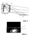
- FIG. 1 shows a block diagram of an embodiment of the night vision system 1 according to the invention for motor vehicles.
- the night vision system 1 has a control unit 3, which is connected to the other components of the system, controls these and processes their signals and data.
- the control unit 3 switches on the NIR high-beam headlights 5.
- These headlights 5 light up in the NIR wavelength range (780 to about 1100nm) a similar spatial area as in conventional high beam in front of the motor vehicle. The range is about 250 meters.
- a camera 7 with CCD or CMOS image sensor (in each case with a linear or nonlinear intensity characteristic curve) which is also sensitive to the NIR range and has a depth of field depth of approximately 2m to infinity, inter alia, detects those of objects which are located in the NIR high-beam range NIR radiation.
- the camera 7 is equipped with an optical filter element 9 arranged in the beam path of the night vision system 1, with which the radiation is attenuated on a predetermined partial area of the image sensor surface 11 in the camera 7.
- the image sensor surface is for example a CCD or CMOS chip
- the image data captured by the camera 7 are transmitted via the control unit 3 to a display unit 15.
- the image of the camera is visualized on a display 17 for the driver.
- the display 17 is, for example, a so-called "head-up display" with which the visualized image of the camera for the driver is clearly visible thrown on a lower part of the windshield.
- FIG. 2 is a cross-section of a camera 7 with the beam path of a night vision system according to the invention arranged filter element 9 for attenuation detected radiation from the vicinity 20 schematically sketched.
- a filter element 9 is located directly in front of the partial area of the image sensor onto which the near area is imaged.
- the dashed lines represent the marginal rays of the beam starting from the front and rear ends of the beam Close range 20.
- the position of the filter element is selected so that all falling from the near area on the image sensor surface rays go through the filter element 9.
- the solid lines represent the main point beam of the front or rear edge point of the near zone.
- the dotted lines represent a specific, arbitrary point from the far end, which, as shown in the drawing, is not attenuated by the filter element 9.
- the filter element 9 should be as close as possible to the image sensor surface 11 in order to have the sharpest possible boundary between near-field imaging and far-field imaging with as little overlap as possible so that as few rays of pixels as possible are filtered out of the far-field many rays from the near zone 20 are filtered by the filter 9.
- the filter element 9 is arranged according to the invention.
- the filter element 9 may consist of the material / layers of a commercially available interference filter or absorption filter. This filter 9 attenuates the radiation from the near zone 20 according to its wavelength characteristic.
- a filter whose attenuation of the radiation has the inverse location-dependent characteristic of the image of the low beam of the motor vehicle, mounted in front of the image sensor surface 11.
- filter elements that extend beyond the pure near range Cover area, possible.
- These have, for example, a location-dependent filter characteristic, which are based on the total intensity of the radiation detected by the camera 7 and thus not only correct an over-radiation of the near range, but additionally also compensate inhomogeneities in the far range by an inverse characteristic.
- a homogeneous intensity of the entire field of view of the camera can be achieved, so that, for example, the vignetting is compensated.
- the filter 9 or the filter coating can then influence the entire imager surface or only parts thereof.
- the filter 9 may also have a wavelength-dependent transmission characteristic. In addition, a combination of location-dependent and wavelength-dependent characteristics is possible.
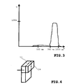
- FIG. 3 an example of such a wavelength-dependent transmission characteristic of the filter is shown in diagram form.
- the transmission rate T is a function over the wavelength A.
- the attenuation for the visible range (380-780nm) is very strong at about 90%.
- the suppression of radiation in the NIR range (780-1100nm) is only about 4%.
- a combination of the location-dependent characteristic with a wavelength-specific transmission characteristic also achieves a strong attenuation of the NIR radiation from the near field and an equally good transmission of VIS and NIR radiation for the remaining image sensor surface area.
- FIG. 4 an embodiment of an inventively coated with an optical filter image sensor surface 11 is set out for use in a night vision system for motor vehicles sketched.
- the image sensor surface 11 has a coating that attenuates depending on the location only for a portion 24 of the image sensor surface incident there radiation.
- the coating 24 is made of a suitable material, as mentioned above.
- the filter effect can have a location-dependent characteristic, which is achieved, for example, by applying different coatings at different locations.
Landscapes
- Engineering & Computer Science (AREA)
- Physics & Mathematics (AREA)
- General Physics & Mathematics (AREA)
- Multimedia (AREA)
- Computer Networks & Wireless Communication (AREA)
- Radar, Positioning & Navigation (AREA)
- Remote Sensing (AREA)
- Optics & Photonics (AREA)
- Toxicology (AREA)
- Electromagnetism (AREA)
- Health & Medical Sciences (AREA)
- Mechanical Engineering (AREA)
- Signal Processing (AREA)
- Studio Devices (AREA)
- Blocking Light For Cameras (AREA)
- Closed-Circuit Television Systems (AREA)
Claims (6)
- Système (1) de vision nocturne pour véhicules automobiles,
comprenant une caméra (7) dotée d'un détecteur d'image (11) destiné à détecter le rayonnement électromagnétique dans la plage visible (VIS) et la plage infrarouge (NIR),
un élément de filtrage (9) étant prévu et disposé dans le parcours des rayons du système (1) de vision nocturne de manière à entraîner une atténuation du rayonnement détecté sur des parties prédéterminées du détecteur d'image,
la caméra (7) étant sensible dans une plage de longueurs d'onde de 400 à 1 100 nm,
l'atténuation du rayonnement provoquée par le filtrage comprenant au moins la partie de la surface (11) du détecteur d'image sur laquelle l'image de la zone proche (20) vue par le conducteur est formée,
la zone proche vue par le conducteur étant la zone située immédiatement en avant du véhicule automobile, suffisamment éclairée pour le conducteur par la lumière des feux de croisement,
l'atténuation étant très prononcée dans la plage visible qui s'étend de 380 nm à 780 nm, de l'ordre de 90 %, la diminution du rayonnement n'étant que d'environ 4 % dans la plage comprise entre 780 nm et 1 100 nm,
caractérisé en ce que
l'élément de filtrage (9) présente une caractéristique de filtrage qui dépend de l'emplacement et est situé immédiatement en avant de la partie du détecteur d'image sur laquelle l'image de la zone proche est formée, de telle sorte que le rayonnement provenant de la zone proche (20) est atténué en fonction de la caractéristique de longueur d'onde de l'élément de filtrage (9) et
en ce que le rayonnement non filtré qui provient de la zone éloignée aboutit sur le reste de la surface (11) du détecteur d'image. - Système (1) de vision nocturne selon la revendication 1, caractérisé en ce que l'élément de filtrage (9) présente une caractéristique de filtrage indépendante de la longueur d'onde et en ce que cette caractéristique présente une fonction de passage adaptée individuellement à l'utilisation particulière du système (1).
- Système (1) de vision nocturne selon l'une des revendications 1 ou 2, caractérisé en ce que l'élément de filtrage (9) est fixé de manière à pouvoir être remplacé.
- Système (1) de vision nocturne selon l'une des revendications 1 ou 2, caractérisé en ce que l'élément de filtrage (9) est prévu comme revêtement (24) sur le détecteur d'image (11).
- Système de vision nocturne selon l'une des revendications 1 ou 2 qui précèdent, dans lequel l'élément de filtrage (9) est configuré comme partie intégrée à un verre de protection du détecteur d'image (11).
- Système (1) de vision nocturne selon l'une des revendications 1 à 5, dans lequel les spectres de la lumière NIR éloignés et de la lumière classique de feux de croisement se superposent aussi peu que possible ou ne se superposent pas.
Applications Claiming Priority (2)
| Application Number | Priority Date | Filing Date | Title |
|---|---|---|---|
| DE102004001556A DE102004001556A1 (de) | 2004-01-10 | 2004-01-10 | Nachtsichtsystem für Kraftfahrzeuge mit partiellem optischem Filter |
| PCT/EP2004/053035 WO2005066684A1 (fr) | 2004-01-10 | 2004-11-22 | Systeme de vision nocturne a filtre optique partiel pour des vehicules automobiles |
Publications (2)
| Publication Number | Publication Date |
|---|---|
| EP1706773A1 EP1706773A1 (fr) | 2006-10-04 |
| EP1706773B1 true EP1706773B1 (fr) | 2010-08-25 |
Family
ID=34716437
Family Applications (1)
| Application Number | Title | Priority Date | Filing Date |
|---|---|---|---|
| EP04820035A Expired - Lifetime EP1706773B1 (fr) | 2004-01-10 | 2004-11-22 | Systeme de vision nocturne a filtre optique partiel pour des vehicules automobiles |
Country Status (5)
| Country | Link |
|---|---|
| US (1) | US20070278406A1 (fr) |
| EP (1) | EP1706773B1 (fr) |
| CN (1) | CN100426046C (fr) |
| DE (2) | DE102004001556A1 (fr) |
| WO (1) | WO2005066684A1 (fr) |
Families Citing this family (32)
| Publication number | Priority date | Publication date | Assignee | Title |
|---|---|---|---|---|
| DE10315741A1 (de) * | 2003-04-04 | 2004-11-04 | Daimlerchrysler Ag | Vorrichtung zur Verbesserung der Sicht in einem Kraftfahrzeug |
| DE102005049307A1 (de) * | 2005-10-12 | 2007-04-19 | Siemens Ag | Bildaufnahmeeinrichtung für den Infrarotbereich |
| WO2007111317A1 (fr) | 2006-03-28 | 2007-10-04 | Kyocera Corporation | Dispositif de vision nocturne |
| US7527440B1 (en) * | 2006-06-05 | 2009-05-05 | White Osborn L | Triangular vehicle light apparatus with camera |
| JP4434234B2 (ja) * | 2007-05-30 | 2010-03-17 | トヨタ自動車株式会社 | 車両用撮像システム、及び車両用制御装置 |
| DE102007053307A1 (de) * | 2007-11-08 | 2009-05-14 | Robert Bosch Gmbh | Kamera zur Erfassung eines Fahrzeugumfeldes |
| DE102008014912B4 (de) | 2008-03-19 | 2023-01-19 | Vorwerk & Co. Interholding Gmbh | Selbsttätig verfahrbares Bodenstaub-Aufsammelgerät |
| DE102008062790A1 (de) * | 2008-12-19 | 2010-06-24 | Visumotion Gmbh | Verfahren und Anordnung zur räumlichen Darstellung |
| DE102009000001B4 (de) | 2009-01-02 | 2019-01-24 | Robert Bosch Gmbh | Bildsensor und Verfahren zur Herstellung eines Bildsensors |
| DE102009036595A1 (de) * | 2009-08-07 | 2011-02-10 | Conti Temic Microelectronic Gmbh | Bildgebender Multifunktions-Sensor |
| JP5525277B2 (ja) * | 2010-02-10 | 2014-06-18 | 株式会社小糸製作所 | カメラを内蔵した車両用灯具 |
| US9507462B2 (en) * | 2012-06-13 | 2016-11-29 | Hong Kong Applied Science and Technology Research Institute Company Limited | Multi-dimensional image detection apparatus |
| US9870753B2 (en) | 2013-02-12 | 2018-01-16 | Gentex Corporation | Light sensor having partially opaque optic |
| JP2016521480A (ja) | 2013-03-22 | 2016-07-21 | セイコーエプソン株式会社 | 赤外線ビデオ表示アイウェア |
| JP6219517B2 (ja) * | 2013-07-26 | 2017-10-25 | ジェンテックス コーポレイション | 部分的に不透明なオプティックを持つ光センサー |
| US9485439B2 (en) | 2013-12-03 | 2016-11-01 | Sensors Unlimited, Inc. | Shortwave infrared camera with bandwidth restriction |
| US10095086B2 (en) * | 2013-12-23 | 2018-10-09 | Lg Electronics Inc. | Camera module |
| DE102014201181A1 (de) * | 2014-01-23 | 2015-07-23 | Robert Bosch Gmbh | Kamerasystem, insbesondere für ein Fahrzeug, und Verfahren zur Ermittlung von Bildinformationen einer zeitlich gepulsten Signalquelle |
| EP3428522A1 (fr) * | 2015-03-23 | 2019-01-16 | Koito Manufacturing Co., Ltd. | Dispositif de capture d'images pour véhicule, support de lampe pour véhicule et unité de commande électronique |
| CN104773079A (zh) * | 2015-03-26 | 2015-07-15 | 淮南圣丹网络工程技术有限公司 | 汽车远光盲点显像装置 |
| DE102015005697B4 (de) * | 2015-05-04 | 2019-10-02 | Mekra Lang Gmbh & Co. Kg | Kamerasystem für ein Kraftfahrzeug |
| CN106470299B (zh) * | 2015-08-18 | 2022-12-23 | 杭州海康机器人股份有限公司 | 镜头、摄像机、包裹检测系统和图像处理方法 |
| US11040649B2 (en) * | 2015-12-21 | 2021-06-22 | Koito Manufacturing Co., Ltd. | Vehicular sensor and vehicle provided with same |
| WO2017161520A1 (fr) * | 2016-03-23 | 2017-09-28 | 徐鹤菲 | Système d'imagerie composite et terminal mobile prenant en charge une imagerie par lumière visible et lumière proche infrarouge |
| JP6786302B2 (ja) * | 2016-08-12 | 2020-11-18 | 株式会社小糸製作所 | 照明装置 |
| CN107765258B (zh) * | 2016-08-22 | 2021-02-05 | 原相科技股份有限公司 | 可用来判断参考物件或光源相对位置的光学侦测装置 |
| JP2018031888A (ja) * | 2016-08-24 | 2018-03-01 | 豊田合成株式会社 | 近赤外線センサ用カバー |
| JP6759995B2 (ja) | 2016-11-11 | 2020-09-23 | 株式会社デンソー | 画像処理装置 |
| DE102017210379A1 (de) * | 2017-06-21 | 2018-12-27 | Robert Bosch Gmbh | Bildsensormodul |
| JP6912757B2 (ja) * | 2017-09-08 | 2021-08-04 | 三菱自動車工業株式会社 | 車両の前照灯制御装置 |
| US10582136B2 (en) * | 2018-03-22 | 2020-03-03 | GM Global Technology Operations LLC | Camera apparatus and operating method thereof |
| JP2024081062A (ja) * | 2022-12-05 | 2024-06-17 | パナソニックオートモーティブシステムズ株式会社 | 車載用カメラ |
Family Cites Families (11)
| Publication number | Priority date | Publication date | Assignee | Title |
|---|---|---|---|---|
| US3704375A (en) * | 1970-05-05 | 1972-11-28 | Barnes Eng Co | Monolithic detector construction of photodetectors |
| DE4137551A1 (de) * | 1990-03-10 | 1993-03-11 | Daimler Benz Ag | Anordnung zur verbesserung der sicht, insbesondere in fahrzeugen |
| DE4107850B4 (de) * | 1990-03-10 | 2006-06-29 | Daimlerchrysler Ag | Anordnung zur Verbesserung der Sicht, insbesondere in Fahrzeugen |
| FR2732849B1 (fr) * | 1995-04-07 | 1997-06-20 | Valeo Vision | Dispositif a camera infrarouge pour systeme d'aide a la vision dans un vehicule automobile, et systeme l'incorporant |
| US5781243A (en) * | 1995-05-08 | 1998-07-14 | Hughes Electronics | Display optimization for night vision enhancement systems |
| JPH11194091A (ja) * | 1997-08-20 | 1999-07-21 | Daimler Benz Ag | 車道表面の状態を求める方法及びこの方法を実施する装置 |
| CN2321026Y (zh) * | 1997-10-13 | 1999-05-26 | 广东省普宁市雄鹰实业公司 | 多功能安全驾驶夜视眼镜及眼镜夹镜 |
| US6730913B2 (en) * | 2002-02-21 | 2004-05-04 | Ford Global Technologies, Llc | Active night vision system for vehicles employing short-pulse laser illumination and a gated camera for image capture |
| JP2003259363A (ja) * | 2002-02-27 | 2003-09-12 | Denso Corp | ナイトビジョン装置 |
| DE10315741A1 (de) * | 2003-04-04 | 2004-11-04 | Daimlerchrysler Ag | Vorrichtung zur Verbesserung der Sicht in einem Kraftfahrzeug |
| DE10335189A1 (de) * | 2003-07-30 | 2005-03-03 | Daimlerchrysler Ag | Vorrichtung zur Sichtverbesserung bei Kraftfahrzeugen |
-
2004
- 2004-01-10 DE DE102004001556A patent/DE102004001556A1/de not_active Withdrawn
- 2004-11-22 US US10/583,201 patent/US20070278406A1/en not_active Abandoned
- 2004-11-22 DE DE502004011592T patent/DE502004011592D1/de not_active Expired - Lifetime
- 2004-11-22 EP EP04820035A patent/EP1706773B1/fr not_active Expired - Lifetime
- 2004-11-22 CN CNB2004800402076A patent/CN100426046C/zh not_active Expired - Fee Related
- 2004-11-22 WO PCT/EP2004/053035 patent/WO2005066684A1/fr not_active Ceased
Also Published As
| Publication number | Publication date |
|---|---|
| US20070278406A1 (en) | 2007-12-06 |
| CN1902522A (zh) | 2007-01-24 |
| DE502004011592D1 (de) | 2010-10-07 |
| WO2005066684A1 (fr) | 2005-07-21 |
| CN100426046C (zh) | 2008-10-15 |
| EP1706773A1 (fr) | 2006-10-04 |
| DE102004001556A1 (de) | 2005-08-04 |
Similar Documents
| Publication | Publication Date | Title |
|---|---|---|
| EP1706773B1 (fr) | Systeme de vision nocturne a filtre optique partiel pour des vehicules automobiles | |
| DE102016111783B4 (de) | Anzeigevorrichtung zur Einblendung eines virtuellen Bildes in das Blickfeld eines Benutzers | |
| DE102004050181B4 (de) | Aktives Nachtsichtsystem mit adaptiver Bildgebung | |
| EP1214224B1 (fr) | Dispositif de capteurs automobiles pour detection de l'environnement | |
| DE102004015040A1 (de) | Kamera in einem Kraftfahrzeug | |
| DE10203421C1 (de) | Automobiles Infrarot-Nachtsichtgerät und automobiles Display | |
| DE102017116849A1 (de) | Indirektes Sichtsystem für ein Fahrzeug | |
| EP2844529A1 (fr) | Détection de gouttes de pluie sur un pare-brise au moyen d'une caméra et d'un éclairage | |
| DE102016209526A1 (de) | Projektionseinrichtung und Verfahren zum Projizieren eines virtuellen Bilds in einen Sichtbereich eines Fahrers eines Fahrzeugs | |
| EP1465002B9 (fr) | Caméra avec filtre infrarouge pour améliorer la visibilité dans un véhicule automobile | |
| EP1503224A2 (fr) | Dispositif pour améliorer la visibilité dans véhicules | |
| DE102008042012A1 (de) | Bildaufnahmevorrichtung und Fahrzeug mit einer Bildaufnahmevorrichtung | |
| DE102008043880A1 (de) | Beleuchtungseinheit für ein Fahrzeug, Fahrzeug und Verfahren hierfür | |
| DE102015221970A1 (de) | Projektionsvorrichtung für ein Kraftfahrzeug | |
| DE102006014504B3 (de) | Bilderfassungssystem für Kraft- und Schienenfahrzeuge sowie Verfahren zur elektronischen Bilderfassung | |
| WO2006067005A1 (fr) | Dispositif et procede pour influer sur la lumiere incidente sur un capteur d'images | |
| DE102015005697B4 (de) | Kamerasystem für ein Kraftfahrzeug | |
| WO2019052936A1 (fr) | Affichage d'un véhicule coloré de manière dynamique | |
| DE102004039334B4 (de) | Vorrichtung zur Verbesserung der Sicht in Fahrzeugen und Fahrzeug | |
| DE102008002553B4 (de) | Bildaufnahmeanordnung und Nachtsichtsystem mit einer Bildaufnahmeanordnung | |
| DE10359345B3 (de) | Vorrichtung zur Verbesserung der Sichtverhältniesse in einem Kraftfahrzeug | |
| DE102008031593A1 (de) | Kamerasystem für Kraftfahrzeuge und Verfahren zum Darstellen von Bildern mittels eines Kamerasystems | |
| EP1262369A2 (fr) | Dispositif de vision nocturne pour véhicule | |
| EP1829373B1 (fr) | Dispositif pour observer en continu des objets independamment de la lumiere ambiante | |
| DE102012201761A1 (de) | Vorrichtung und Verfahren zur Lenkung von Strahlung in Richtung eines optischen Elements einer Bilderfassungseinrichtung eines Fahrzeugs |
Legal Events
| Date | Code | Title | Description |
|---|---|---|---|
| PUAI | Public reference made under article 153(3) epc to a published international application that has entered the european phase |
Free format text: ORIGINAL CODE: 0009012 |
|
| 17P | Request for examination filed |
Effective date: 20060810 |
|
| AK | Designated contracting states |
Kind code of ref document: A1 Designated state(s): DE FR IT SE |
|
| DAX | Request for extension of the european patent (deleted) | ||
| RBV | Designated contracting states (corrected) |
Designated state(s): DE FR IT SE |
|
| 17Q | First examination report despatched |
Effective date: 20090210 |
|
| GRAP | Despatch of communication of intention to grant a patent |
Free format text: ORIGINAL CODE: EPIDOSNIGR1 |
|
| GRAS | Grant fee paid |
Free format text: ORIGINAL CODE: EPIDOSNIGR3 |
|
| GRAA | (expected) grant |
Free format text: ORIGINAL CODE: 0009210 |
|
| AK | Designated contracting states |
Kind code of ref document: B1 Designated state(s): DE FR IT SE |
|
| REF | Corresponds to: |
Ref document number: 502004011592 Country of ref document: DE Date of ref document: 20101007 Kind code of ref document: P |
|
| PGFP | Annual fee paid to national office [announced via postgrant information from national office to epo] |
Ref country code: FR Payment date: 20101130 Year of fee payment: 7 |
|
| PG25 | Lapsed in a contracting state [announced via postgrant information from national office to epo] |
Ref country code: SE Free format text: LAPSE BECAUSE OF FAILURE TO SUBMIT A TRANSLATION OF THE DESCRIPTION OR TO PAY THE FEE WITHIN THE PRESCRIBED TIME-LIMIT Effective date: 20100825 |
|
| PG25 | Lapsed in a contracting state [announced via postgrant information from national office to epo] |
Ref country code: IT Free format text: LAPSE BECAUSE OF FAILURE TO SUBMIT A TRANSLATION OF THE DESCRIPTION OR TO PAY THE FEE WITHIN THE PRESCRIBED TIME-LIMIT Effective date: 20100825 |
|
| PGFP | Annual fee paid to national office [announced via postgrant information from national office to epo] |
Ref country code: DE Payment date: 20110125 Year of fee payment: 7 |
|
| PLBE | No opposition filed within time limit |
Free format text: ORIGINAL CODE: 0009261 |
|
| STAA | Information on the status of an ep patent application or granted ep patent |
Free format text: STATUS: NO OPPOSITION FILED WITHIN TIME LIMIT |
|
| 26N | No opposition filed |
Effective date: 20110526 |
|
| REG | Reference to a national code |
Ref country code: DE Ref legal event code: R097 Ref document number: 502004011592 Country of ref document: DE Effective date: 20110526 |
|
| REG | Reference to a national code |
Ref country code: FR Ref legal event code: ST Effective date: 20120731 |
|
| REG | Reference to a national code |
Ref country code: DE Ref legal event code: R119 Ref document number: 502004011592 Country of ref document: DE Effective date: 20120601 |
|
| PG25 | Lapsed in a contracting state [announced via postgrant information from national office to epo] |
Ref country code: FR Free format text: LAPSE BECAUSE OF NON-PAYMENT OF DUE FEES Effective date: 20111130 |
|
| PG25 | Lapsed in a contracting state [announced via postgrant information from national office to epo] |
Ref country code: DE Free format text: LAPSE BECAUSE OF NON-PAYMENT OF DUE FEES Effective date: 20120601 |