EP1580155B1 - Dispositif d'enroulement avec rouleau brosse à transfert - Google Patents
Dispositif d'enroulement avec rouleau brosse à transfert Download PDFInfo
- Publication number
- EP1580155B1 EP1580155B1 EP05251629A EP05251629A EP1580155B1 EP 1580155 B1 EP1580155 B1 EP 1580155B1 EP 05251629 A EP05251629 A EP 05251629A EP 05251629 A EP05251629 A EP 05251629A EP 1580155 B1 EP1580155 B1 EP 1580155B1
- Authority
- EP
- European Patent Office
- Prior art keywords
- transfer
- spindles
- brush
- accordance
- webs
- Prior art date
- Legal status (The legal status is an assumption and is not a legal conclusion. Google has not performed a legal analysis and makes no representation as to the accuracy of the status listed.)
- Expired - Lifetime
Links
Images


Classifications
-
- B—PERFORMING OPERATIONS; TRANSPORTING
- B65—CONVEYING; PACKING; STORING; HANDLING THIN OR FILAMENTARY MATERIAL
- B65H—HANDLING THIN OR FILAMENTARY MATERIAL, e.g. SHEETS, WEBS, CABLES
- B65H19/00—Changing the web roll
- B65H19/22—Changing the web roll in winding mechanisms or in connection with winding operations
-
- B—PERFORMING OPERATIONS; TRANSPORTING
- B65—CONVEYING; PACKING; STORING; HANDLING THIN OR FILAMENTARY MATERIAL
- B65H—HANDLING THIN OR FILAMENTARY MATERIAL, e.g. SHEETS, WEBS, CABLES
- B65H18/00—Winding webs
- B65H18/08—Web-winding mechanisms
- B65H18/14—Mechanisms in which power is applied to web roll, e.g. to effect continuous advancement of web
- B65H18/22—Mechanisms in which power is applied to web roll, e.g. to effect continuous advancement of web by friction band
-
- B—PERFORMING OPERATIONS; TRANSPORTING
- B65—CONVEYING; PACKING; STORING; HANDLING THIN OR FILAMENTARY MATERIAL
- B65H—HANDLING THIN OR FILAMENTARY MATERIAL, e.g. SHEETS, WEBS, CABLES
- B65H19/00—Changing the web roll
- B65H19/22—Changing the web roll in winding mechanisms or in connection with winding operations
- B65H19/2207—Changing the web roll in winding mechanisms or in connection with winding operations the web roll being driven by a winding mechanism of the centre or core drive type
-
- B—PERFORMING OPERATIONS; TRANSPORTING
- B65—CONVEYING; PACKING; STORING; HANDLING THIN OR FILAMENTARY MATERIAL
- B65H—HANDLING THIN OR FILAMENTARY MATERIAL, e.g. SHEETS, WEBS, CABLES
- B65H19/00—Changing the web roll
- B65H19/22—Changing the web roll in winding mechanisms or in connection with winding operations
- B65H19/28—Attaching the leading end of the web to the replacement web-roll core or spindle
-
- B—PERFORMING OPERATIONS; TRANSPORTING
- B65—CONVEYING; PACKING; STORING; HANDLING THIN OR FILAMENTARY MATERIAL
- B65H—HANDLING THIN OR FILAMENTARY MATERIAL, e.g. SHEETS, WEBS, CABLES
- B65H2301/00—Handling processes for sheets or webs
- B65H2301/40—Type of handling process
- B65H2301/41—Winding, unwinding
- B65H2301/414—Winding
- B65H2301/41419—Starting winding process
- B65H2301/41422—Starting winding process involving mechanical means
- B65H2301/414222—Starting winding process involving mechanical means fixed to frame, tucking leading edge to core, e.g. by brush
-
- B—PERFORMING OPERATIONS; TRANSPORTING
- B65—CONVEYING; PACKING; STORING; HANDLING THIN OR FILAMENTARY MATERIAL
- B65H—HANDLING THIN OR FILAMENTARY MATERIAL, e.g. SHEETS, WEBS, CABLES
- B65H2301/00—Handling processes for sheets or webs
- B65H2301/40—Type of handling process
- B65H2301/41—Winding, unwinding
- B65H2301/414—Winding
- B65H2301/4146—Winding involving particular drive arrangement
- B65H2301/41466—Winding involving particular drive arrangement combinations of drives
- B65H2301/41468—Winding involving particular drive arrangement combinations of drives centre and nip drive
-
- B—PERFORMING OPERATIONS; TRANSPORTING
- B65—CONVEYING; PACKING; STORING; HANDLING THIN OR FILAMENTARY MATERIAL
- B65H—HANDLING THIN OR FILAMENTARY MATERIAL, e.g. SHEETS, WEBS, CABLES
- B65H2408/00—Specific machines
- B65H2408/20—Specific machines for handling web(s)
- B65H2408/23—Winding machines
- B65H2408/231—Turret winders
- B65H2408/2315—Turret winders specified by number of arms
- B65H2408/23157—Turret winders specified by number of arms with more than three arms
Definitions
- the present invention relates generally to an apparatus for winding webs of material into individual rolls, and more particularly to a winder apparatus having a brush roll assembly which facilitates efficient transfer of serially conveyed webs of material onto associated winding spindles of the apparatus.
- An apparatus of this nature includes a conveyor along which the webs of material are serially conveyed, and an associated, indexable winding turret having a plurality of winding spindles mounted thereon.
- the spindles of the winding turret can each be indexed to a so-called transfer position, with winding of a roll initiated by transferring a leading edge portion of one of the material webs onto the winding spindle.
- the spindle is rotatably driven in coordination with speed at which the webs are conveyed, thereby forming a coreless roll on the spindle.
- another spindle is presented at the transfer position for winding, while rolls previously formed on the turret spindles are moved at a discharge position through which the spindles are indexed.
- U.S. Patent No. 5,779,180 discloses a drive arrangement for effecting drive of the winding spindles, with a typical winder apparatus exemplified by commercially available Hudson-Sharp M-450 continuous motion winder. Another example for a winder to be regarded as closest prior art is disclosed in US 5,337,968 .
- operation of such a winder apparatus can inadvertently result in mis-transfer of one of the webs of material, that is, failure to initiate the intended winding of the web onto the winding spindle at the transfer position.
- mis-transfers undesirably results in wasted product and undesirable down time for the equipment.
- initiation of web winding has been effected by the provision of an air horn which acts upon the leading portion of the web of material to effect transfer to the associated winding spindle in the transfer position.
- a air blast from the air horn is precisely timed so as to direct air at the web on the conveyor, forcing the web off of the conveyor and around the winding spindle which is positioned in operative association with the air horn.
- this existing transfer arrangement can sometimes undesirably result in mis-transfer of the webs of material.
- this particular component of the winding apparatus is a relatively expensive part to fabricate, entailing substantial machine work for its manufacture.
- the present invention is directed to a winder apparatus including an improved arrangement for effecting web transfer, which not only desirably precludes inadvertent mis-transfers, which is also desirably straightforward in configuration for economical manufacture and use.
- the present invention is directed to a winder apparatus for winding webs of materials into coreless rolls, with the apparatus including an improved arrangement for effecting transfer of the webs onto associated winding spindles for initiating winding thereon.
- the apparatus includes a rotatably driven transfer brush assembly positioned in operative association with an apparatus conveyor and the winding spindles, with the brush assembly configured to engage the leading edge portion of one of the webs, and thereby deflect and transfer the web from the conveyor onto the associated winding spindle to initiate winding.
- the arrangement is desirably straight forward in construction for economical manufacture and use, with highly consistent and reliable web-transfer achieved.
- the present winder apparatus includes a conveyor for serially conveying webs of material to be wound into rolls.
- webs typically comprise bags formed from plastic film material, which may be arranged in interleaved relationship, or in end-to-end array.
- the apparatus includes an indexable winding turret having a plurality of winding spindles thereon.
- the turret is indexable to position each of the spindles in a transfer position, in operative association with, and generally transversely of, the conveyor on which the webs are moved.
- the winder apparatus includes a rotatably driven transfer brush assembly positionable in operative association with the web conveyor, generally transversely thereof.
- the transfer brush assembly includes at least one rotatable brush wheel, which is rotatable in a direction opposite to that direction in which the webs of material are conveyed by the associated conveyor, and at a speed equal to or faster than the liner speed of each web.
- each of the winding spindles includes air passageways, with application of vacuum through these passageways facilitating initiation of winding, and the direction of air pressure outwardly through the passageways facilitating discharge of a completed roll from the spindle after the turret is indexed to present the roll at a discharge position.
- the transfer brush assembly includes a plurality of the brush wheels positioned in spaced apart relationship.
- the apparatus further preferably includes a plurality of spaced apart guide fingers which are positionable generally about the one of the winding spindles in the transfer position.
- the brush wheels are each positioned between a respective adjacent pair of the guide fingers, with the guide fingers and transfer brush assembly preferably mounted for movement together on a movable frame which can be brought into operative association with a winding spindle at the transfer position after indexed movement of the associated winding turret.
- the apparatus includes a support roll positioned beneath the conveyor for cooperation with the transfer brush assembly, thereby facilitating transfer of each of the webs from the conveyor onto the associated winding spindle.
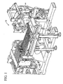
- winder apparatus 10 embodying the principals of the present invention.
- winder apparatus 10 is configured to wind webs of material, typically plastic film bags arranged in an interleaved relationship or end-to-end arrays, into individual, coreless rolls. After winding into individual rolls, the rolls are discharged from the apparatus for subsequent handling.
- Winder apparatus 10 includes a frame on which a conveyor 12 is mounted for serially conveying the webs of material therealong.
- the apparatus further includes a selectively indexable, winding turret 14 having a plurality of winding spindles 16 mounted thereon.
- Winding turret 14 is indexed during operation of apparatus 10 so that each of the winding spindles 16 thereon are moved through four distinct positions. These include a transfer position, at which the spindle is positioned in operative association with conveyor 12 for initiating winding of a roll of material thereon. In a final wind position, winding of the roll of material is completed. In a discharge position, the roll of wound material is ejected from the spindle. Finally, each spindle is indexed through a ready position, prior to being indexed to the transfer position, before repeating the cycle.
- a transfer brush assembly 18 is positionable in operative association with the conveyor 12, and one of the spindles 16 in the transfer position thereof, to thereby effect transfer of a leading edge portion of one of the webs of material being conveyed onto the spindle in the transfer position to thereby initiate winding into a roll.
- the transfer brush assembly comprises at least one, and preferably a plurality of generally circular brush wheels 20 positioned in spaced apart relationship along a mounting shaft 22.
- each of the rotatable brush wheels 20 has a three inch diameter, a face width of approximately 0.5 inches, with 16 mil bristles, such as commercially available from Brush Research Manufacturing, under designation CN-3.
- the brush wheels are spaced apart on the shaft 22 by the provision of suitable rubber donut-shaped spacers (not shown) positioned along the shaft, and are thus rotatable together about an axis extending transversely of the conveyor.
- the brush wheels 20 of the transfer brush assembly are positionable in operative association with the conveyor 12 so as to be engageable with the conveyor, and thus engageable with a leading edge portion of one of the webs of material being conveyed thereon. Transfer of the web to the associated spindle 16 in its transfer position is facilitated by rotatably driving the transfer brush assembly in a direction opposite to the direction of movement of the webs of material, that is, in a clockwise direction referring to the orientation of FIGURE 3 .
- each of the transfer spindles 16 is shown in its transfer position, with the spindle being rotatably driven in a direction opposite to the direction of rotation of transfer brush assembly 18 (i.e., spindle 16 is driven in a counter-clockwise direction, referring to the orientation of FIGURE 3 ).
- spindle 16 is driven in a counter-clockwise direction, referring to the orientation of FIGURE 3 .
- the leading edge portion of the web is urged generally upwardly and about the rotating spindle 16.
- each of the spindles 16 defines a plurality of air passageways 24 ( FIGURE 2 ) at the periphery thereof.
- the winder apparatus includes a plurality of guide fingers 26 positionable in operative association with the spindle in the transfer position.
- the spaced apart brush wheels 20 are each positioned between a respective pair of the guide fingers 26, with the guide fingers 26 extending generally about the one of the spindles 16 in the transfer position as winding is initiated.
- the guide fingers thus act to guide the leading edge portion of the web onto the spindle, as transfer is effected by the rotating transfer brush assembly 18.
- the winder apparatus can include a support roll 27 positioned beneath the conveyor generally opposite the brush assembly.
- the support roll cooperates and coacts with the brush assembly to urge each web off of the conveyor for transfer to the associated winding spindle
- the support roll can be mounted for movement, if desired, to permit the support roll to be periodically urged upwardly toward the brush assembly to promote engagement of the brush assembly with the web to be transferred.
- the support roll can thus be configured to function as a so-called kick roll, and operated in conjunction with the transferring action of the brush assembly, to promote consistent web transfer.
- transfer brush assembly 20, and the associated guide fingers 26 are moved to an out-of-the-way disposition, to thereby facilitate unencumbered indexing rotation of the winding turret 14.
- the brush wheel assembly and guide fingers are mounted on a movable frame 28 for movement together relative to the one of the spindles in the transfer position.
- FIGURES 2 and 3 illustrate the movable frame 28, with guide fingers 26 and transfer brush assembly 18, positioned in such operative association with the illustrated spindle 16.
- the frame 28 Prior to indexing rotation of the turret 14, the frame 28 is pivoted generally upwardly in a counterclockwise direction by one or more appropriate actuators, preferably a pair of pneumatic cylinders.
- the first of the pneumatic cylinders effects the major portion of the motion of movable frame 28, while a second one of the cylinders urges the frame, and transfer roller 18, into position for operative engagement with the conveyor 12, and the associated spindle 16 in its transfer position.
- FIGURE 1 illustrates a drive arrangement for the rotatably driven transfer brush assembly 18, including a drive pulley 30, and a drive belt 32.
- the transfer brush assembly is appropriately driven at a speed which is equal to, or faster than, the linear speed of the web of material being conveyed on conveyor 12.
- the orientation of the transfer brush assembly, including brush wheels 20, is such that the brush wheels are in contact with the conveyor and the spindle 16 simultaneously, so that the resulting sweeping action of the brush wheels effects a positive transfer up from the conveyor onto the spindle 16.
- the preferred provision of curved guide fingers 26 extending generally about the spindle 16 desirably acts to ensure that the web travels around the spindle during transfer.
- the movable frame 28 can be pivoted for moving the transfer brush assembly 18 and the associated guide fingers 26 out of their operative position.
- the turret 14 is indexed to move the rotating spindle 16 to its final wind position to complete roll formation.
Landscapes
- Replacement Of Web Rolls (AREA)
Claims (12)
- Dispositif d'enroulement (10) pour enrouler des bandes de matériau en rouleaux, comprenant :un transporteur (12) pour transporter en série ladite bande de matériau ;une tourelle sélectivement indexable (14) comportant une pluralité de broches à bobiner (16) sur celle-ci, ladite tourelle (14) étant indexable pour positionner chacune desdites broches (16) dans une position de transfert en association opérative avec ledit transporteur (12) pour initialiser l'enroulement de l'une desdites bandes de matériau sur l'une desdites broches (16) dans ladite position de transfert, caractérisé par :un assemblage de brosses de transfert (18) positionnable en association opérative avec ledit transporteur (12), ledit assemblage de brosses (18) étant engageable avec ladite une desdites bandes de matériau pour le transfert de ladite une desdites bandes dans ladite une desdites broches (16) dans ladite position de transfert.
- Dispositif d'enroulement (10) selon la revendication 1, dans lequel :ledit assemblage de brosses (18) comprend au moins une roue de brosse rotative (20).
- Dispositif d'enroulement (10) selon la revendication 2, dans lequel :ladite roue de brosse rotative (20) tourne dans une direction opposée à la direction dans laquelle ladite une desdites bandes est transportée sur le transporteur.
- Dispositif d'enroulement (10) selon la revendication 1, 2 ou 3, dans lequel :ledit assemblage de brosses (18) comprend une pluralité de roues de brosse généralement circulaires (20) pouvant tourner ensemble sur un axe s'étendant transversalement par rapport au transporteur (12).
- Dispositif d'enroulement (10) selon l'une quelconque des revendications 1 à 4, dans lequel :ledit dispositif inclut une pluralité de doigts de guidage (26) positionnables généralement autour de ladite une desdites broches (16) dans ladite position de transfert,ladite pluralité de roues de brosse (20) étant espacées et chacune étant positionnée entre une paire respective adjacente desdits doigts de guidage (26).
- Dispositif d'enroulement (10) selon la revendication 5, dans lequel :ledit assemblage de brosses (18) et lesdits doigts de guidage (26) sont montés sur un cadre pour se déplacer ensemble par rapport à l'une desdites broches (16) dans ladite position de transfert.
- Dispositif d'enroulement (10) selon la revendication 1, dans lequel :l'assemblage de brosses de transfert (18) est positionnable en association opérative avec ledit transporteur (12) de manière généralement transversale à celui-ci, et dans lequelledit assemblage de brosses de transfert (18) inclut au moins une roue de brosse rotative (20) pouvant tourner dans une direction opposée à la direction dans laquelle les bandes sont transportées.
- Dispositif d'enroulement (10) selon la revendication 7, dans lequel :ladite roue de brosse (20) est engageable avec ladite une desdites broches (16) dans ladite position de transfert.
- Dispositif d'enroulement (10) selon la revendication 7 ou 8, dans lequel :ledit assemblage de brosses de transfert (18) inclut une pluralité desdites roues de brosse rotatives (20).
- Dispositif d'enroulement (10) selon la revendication 7, 8 ou 9, dans lequel :ledit dispositif inclut une pluralité de doigts de guidage (26) positionnables généralement autour de ladite une desdites broches (16) dans ladite position de transfert, ladite pluralité de roues de brosse (20) étant espacées et chacune positionnée entre une paire respective desdits doigts de guidage (26),ledit dispositif incluant un cadre mouvant (28) sur lequel lesdits doigts de guidage (26) et ledit assemblage de brosses de transfert (18) sont montés pour se déplacer ensemble par rapport à l'une desdites broches (16) dans ladite position de transfert.
- Dispositif d'enroulement (10) selon l'une quelconque des revendications 7 à 10, dans lequel :chacune desdites broches (16) définit une pluralité de voies de passage d'air à la périphérie de celui-ci.
- Dispositif d'enroulement (10) selon l'une quelconque des revendications 7 à 11, incluant :un rouleau de support (27) positionné en dessous dudit transporteur pour une coopération avec ledit assemblage de brosses (18) pour faciliter le transfert de chacune desdites bandes.
Applications Claiming Priority (2)
| Application Number | Priority Date | Filing Date | Title |
|---|---|---|---|
| US810366 | 2001-03-15 | ||
| US10/810,366 US7108219B2 (en) | 2004-03-26 | 2004-03-26 | Winder apparatus with transfer brush roll |
Publications (3)
| Publication Number | Publication Date |
|---|---|
| EP1580155A2 EP1580155A2 (fr) | 2005-09-28 |
| EP1580155A3 EP1580155A3 (fr) | 2007-03-28 |
| EP1580155B1 true EP1580155B1 (fr) | 2009-05-13 |
Family
ID=34862110
Family Applications (1)
| Application Number | Title | Priority Date | Filing Date |
|---|---|---|---|
| EP05251629A Expired - Lifetime EP1580155B1 (fr) | 2004-03-26 | 2005-03-17 | Dispositif d'enroulement avec rouleau brosse à transfert |
Country Status (4)
| Country | Link |
|---|---|
| US (1) | US7108219B2 (fr) |
| EP (1) | EP1580155B1 (fr) |
| DE (1) | DE602005014406D1 (fr) |
| ES (1) | ES2325449T3 (fr) |
Cited By (1)
| Publication number | Priority date | Publication date | Assignee | Title |
|---|---|---|---|---|
| US12280560B2 (en) | 2022-05-20 | 2025-04-22 | Cmd Corporation | Bag making machines and methods thereof |
Families Citing this family (6)
| Publication number | Priority date | Publication date | Assignee | Title |
|---|---|---|---|---|
| US7578779B2 (en) * | 2006-09-14 | 2009-08-25 | Cmd Corporation | Bag machine and winder |
| US20090019817A1 (en) * | 2006-09-14 | 2009-01-22 | Cmd Corporation | Bag Machine And Winder |
| ITMI20061814A1 (it) * | 2006-09-26 | 2008-03-27 | Colines Srl | Impianto avvolgitore per impiego in linee di produzione di film plastici,in particolare film plastici estensibili,e metodo di avvolgimento di bobine di film plastici |
| NL2000854C2 (nl) * | 2007-09-12 | 2009-03-18 | Global Factories B V | Wikkelinrichting. |
| DK3274283T3 (da) | 2015-03-23 | 2021-08-16 | Roll O Matic As | Opviklingsindretning til et banemateriale |
| CN108341291B (zh) * | 2018-03-30 | 2024-02-02 | 厦门攸信信息技术有限公司 | 直线式卷纸包装机及其控制方法 |
Family Cites Families (10)
| Publication number | Priority date | Publication date | Assignee | Title |
|---|---|---|---|---|
| US3782650A (en) * | 1972-04-28 | 1974-01-01 | Egan Machinery Co | Web winder control |
| DE2619236C3 (de) * | 1976-04-30 | 1989-06-08 | Siemens AG, 1000 Berlin und 8000 München | Verfahren zur Steuerung des fliegenden Anschließens einer Bahn von einer zweiten Wickelrolle an eine von einer ersten Wickelrolle überlaufende Bahn |
| US4667890A (en) * | 1985-07-15 | 1987-05-26 | Custom Machinery Design, Inc. | Coreless winder |
| DE3710142A1 (de) * | 1987-03-31 | 1988-10-13 | Jagenberg Ag | Verfahren und vorrichtung zum einziehen einer papierbahn in eine rollmaschine |
| DE4010894C2 (de) * | 1990-04-04 | 1996-11-28 | Fmc Corp | Revolverkopfaufwickel-Vorrichtung zum Aufwickeln von Bahnmaterial, insbesondere von aus Kunststoffolien bestehenden, in Bandform zusammenhängenden Beuteln |
| US5161793A (en) * | 1991-02-06 | 1992-11-10 | Fmc Corporation | Interleaving apparatus for rolled up segments |
| US5318237A (en) * | 1992-10-08 | 1994-06-07 | Fmc Corporation | Air horn for web winding machine |
| US5899403A (en) * | 1994-05-24 | 1999-05-04 | Cmd Corporation | Method and apparatus for winding bags onto a spindle |
| US5779180A (en) * | 1996-10-18 | 1998-07-14 | Fmc Corporation | Winder for use with bag-making machine |
| JP4585136B2 (ja) * | 2001-03-29 | 2010-11-24 | メッツォペーパージャパン株式会社 | 巻取ロール押さえ装置および長尺材巻取り方法 |
-
2004
- 2004-03-26 US US10/810,366 patent/US7108219B2/en not_active Expired - Lifetime
-
2005
- 2005-03-17 ES ES05251629T patent/ES2325449T3/es not_active Expired - Lifetime
- 2005-03-17 DE DE602005014406T patent/DE602005014406D1/de not_active Expired - Lifetime
- 2005-03-17 EP EP05251629A patent/EP1580155B1/fr not_active Expired - Lifetime
Cited By (4)
| Publication number | Priority date | Publication date | Assignee | Title |
|---|---|---|---|---|
| US12280560B2 (en) | 2022-05-20 | 2025-04-22 | Cmd Corporation | Bag making machines and methods thereof |
| US12485637B2 (en) | 2022-05-20 | 2025-12-02 | Cmd Corporation | Bag making machines and methods thereof |
| US12496797B2 (en) | 2022-05-20 | 2025-12-16 | Cmd Corporation | Bag making machines and methods thereof |
| US12600107B2 (en) | 2022-05-20 | 2026-04-14 | Cmd Corporation | Bag making machines and methods thereof |
Also Published As
| Publication number | Publication date |
|---|---|
| EP1580155A3 (fr) | 2007-03-28 |
| EP1580155A2 (fr) | 2005-09-28 |
| US7108219B2 (en) | 2006-09-19 |
| ES2325449T3 (es) | 2009-09-04 |
| DE602005014406D1 (de) | 2009-06-25 |
| US20050211818A1 (en) | 2005-09-29 |
Similar Documents
| Publication | Publication Date | Title |
|---|---|---|
| CN101970321B (zh) | 索引卷绕机上卷绕芯的设备 | |
| US6595458B1 (en) | Method and device for the production of rolls of web material without a winding core | |
| US5000729A (en) | Bag folding machine | |
| US5150848A (en) | Re-reeling machine working at constant speed and related cutting device | |
| CA2746294A1 (fr) | Tambour servant a couper et transferer des etiquettes sans endos provenant d'une bande continue vers un contenant en mouvement, et appareil equipe dudit tambour | |
| US20040159999A1 (en) | Conveying roller for a paper web, machines equipped therewith and methods of use | |
| US7108219B2 (en) | Winder apparatus with transfer brush roll | |
| EP3274283B1 (fr) | Appareil d'enroulement de matière de bande continue | |
| US12024396B2 (en) | Machine and method for providing rolls of material for use in sheet form, particularly aluminum for food uses, of the coreless type | |
| US4954033A (en) | Transfer mechanism for conveyor | |
| US6761329B2 (en) | Apparatus and method of producing rolls of bags | |
| EP3526125B1 (fr) | Appareil de fabrication de rouleau avec dispositif d'enveloppage | |
| US5899403A (en) | Method and apparatus for winding bags onto a spindle | |
| JPS63106264A (ja) | 細幅帯状体の供給装置 | |
| JP4357027B2 (ja) | シート状部材の製造方法および装置 | |
| US4473431A (en) | Apparatus for making plastic material bags and for depositing them in groups | |
| EP0810172A2 (fr) | Appareil à fabriquer des rouleaux pour bandes continues ou enchevêtrées | |
| CN219362705U (zh) | Pet片材自动换芯收卷机构 | |
| CN222006711U (zh) | 一种垃圾袋收卷装置 | |
| RU2781647C2 (ru) | Машина и способ получения выполненных без сердечника рулонов материала, предназначенного для использования в виде листа, в частности алюминиевого, предназначенного для использования для пищевых продуктов | |
| JPS6245890Y2 (fr) | ||
| JPS62146857A (ja) | ウエブロ−ル製造装置及びウエブロ−ル製造方法 | |
| JPH0736933Y2 (ja) | ウエブの多条巻取装置 | |
| US20190367200A1 (en) | Packaging sleeve feeding device | |
| TH39800A (th) | แกนม้วนเก็บของโครงระดับ a ที่ได้รับการม้วนที่พื้นผิว |
Legal Events
| Date | Code | Title | Description |
|---|---|---|---|
| PUAI | Public reference made under article 153(3) epc to a published international application that has entered the european phase |
Free format text: ORIGINAL CODE: 0009012 |
|
| AK | Designated contracting states |
Kind code of ref document: A2 Designated state(s): AT BE BG CH CY CZ DE DK EE ES FI FR GB GR HU IE IS IT LI LT LU MC NL PL PT RO SE SI SK TR |
|
| AX | Request for extension of the european patent |
Extension state: AL BA HR LV MK YU |
|
| PUAL | Search report despatched |
Free format text: ORIGINAL CODE: 0009013 |
|
| AK | Designated contracting states |
Kind code of ref document: A3 Designated state(s): AT BE BG CH CY CZ DE DK EE ES FI FR GB GR HU IE IS IT LI LT LU MC NL PL PT RO SE SI SK TR |
|
| AX | Request for extension of the european patent |
Extension state: AL BA HR LV MK YU |
|
| 17P | Request for examination filed |
Effective date: 20070905 |
|
| AKX | Designation fees paid |
Designated state(s): BE DE ES FR GB IT |
|
| GRAP | Despatch of communication of intention to grant a patent |
Free format text: ORIGINAL CODE: EPIDOSNIGR1 |
|
| GRAS | Grant fee paid |
Free format text: ORIGINAL CODE: EPIDOSNIGR3 |
|
| GRAA | (expected) grant |
Free format text: ORIGINAL CODE: 0009210 |
|
| AK | Designated contracting states |
Kind code of ref document: B1 Designated state(s): BE DE ES FR GB IT |
|
| REG | Reference to a national code |
Ref country code: GB Ref legal event code: FG4D |
|
| REF | Corresponds to: |
Ref document number: 602005014406 Country of ref document: DE Date of ref document: 20090625 Kind code of ref document: P |
|
| REG | Reference to a national code |
Ref country code: ES Ref legal event code: FG2A Ref document number: 2325449 Country of ref document: ES Kind code of ref document: T3 |
|
| PG25 | Lapsed in a contracting state [announced via postgrant information from national office to epo] |
Ref country code: BE Free format text: LAPSE BECAUSE OF FAILURE TO SUBMIT A TRANSLATION OF THE DESCRIPTION OR TO PAY THE FEE WITHIN THE PRESCRIBED TIME-LIMIT Effective date: 20090513 |
|
| PLBE | No opposition filed within time limit |
Free format text: ORIGINAL CODE: 0009261 |
|
| STAA | Information on the status of an ep patent application or granted ep patent |
Free format text: STATUS: NO OPPOSITION FILED WITHIN TIME LIMIT |
|
| 26N | No opposition filed |
Effective date: 20100216 |
|
| PG25 | Lapsed in a contracting state [announced via postgrant information from national office to epo] |
Ref country code: IT Free format text: LAPSE BECAUSE OF FAILURE TO SUBMIT A TRANSLATION OF THE DESCRIPTION OR TO PAY THE FEE WITHIN THE PRESCRIBED TIME-LIMIT Effective date: 20090513 |
|
| REG | Reference to a national code |
Ref country code: FR Ref legal event code: PLFP Year of fee payment: 12 |
|
| REG | Reference to a national code |
Ref country code: FR Ref legal event code: PLFP Year of fee payment: 13 |
|
| REG | Reference to a national code |
Ref country code: FR Ref legal event code: PLFP Year of fee payment: 14 |
|
| PGFP | Annual fee paid to national office [announced via postgrant information from national office to epo] |
Ref country code: FR Payment date: 20230327 Year of fee payment: 19 |
|
| PGFP | Annual fee paid to national office [announced via postgrant information from national office to epo] |
Ref country code: GB Payment date: 20230327 Year of fee payment: 19 Ref country code: DE Payment date: 20230329 Year of fee payment: 19 |
|
| PGFP | Annual fee paid to national office [announced via postgrant information from national office to epo] |
Ref country code: ES Payment date: 20230403 Year of fee payment: 19 |
|
| REG | Reference to a national code |
Ref country code: DE Ref legal event code: R119 Ref document number: 602005014406 Country of ref document: DE |
|
| GBPC | Gb: european patent ceased through non-payment of renewal fee |
Effective date: 20240317 |
|
| PG25 | Lapsed in a contracting state [announced via postgrant information from national office to epo] |
Ref country code: DE Free format text: LAPSE BECAUSE OF NON-PAYMENT OF DUE FEES Effective date: 20241001 |
|
| PG25 | Lapsed in a contracting state [announced via postgrant information from national office to epo] |
Ref country code: GB Free format text: LAPSE BECAUSE OF NON-PAYMENT OF DUE FEES Effective date: 20240317 |
|
| PG25 | Lapsed in a contracting state [announced via postgrant information from national office to epo] |
Ref country code: FR Free format text: LAPSE BECAUSE OF NON-PAYMENT OF DUE FEES Effective date: 20240331 |
|
| PG25 | Lapsed in a contracting state [announced via postgrant information from national office to epo] |
Ref country code: GB Free format text: LAPSE BECAUSE OF NON-PAYMENT OF DUE FEES Effective date: 20240317 Ref country code: FR Free format text: LAPSE BECAUSE OF NON-PAYMENT OF DUE FEES Effective date: 20240331 Ref country code: DE Free format text: LAPSE BECAUSE OF NON-PAYMENT OF DUE FEES Effective date: 20241001 |
|
| REG | Reference to a national code |
Ref country code: ES Ref legal event code: FD2A Effective date: 20250430 |
|
| PG25 | Lapsed in a contracting state [announced via postgrant information from national office to epo] |
Ref country code: ES Free format text: LAPSE BECAUSE OF NON-PAYMENT OF DUE FEES Effective date: 20240318 |