EP1580524B1 - Verfahren und Vorrichtung zur Charakterisierung von Strukturschäden mittels Moiré- Schatten - Google Patents
Verfahren und Vorrichtung zur Charakterisierung von Strukturschäden mittels Moiré- Schatten Download PDFInfo
- Publication number
- EP1580524B1 EP1580524B1 EP05290646A EP05290646A EP1580524B1 EP 1580524 B1 EP1580524 B1 EP 1580524B1 EP 05290646 A EP05290646 A EP 05290646A EP 05290646 A EP05290646 A EP 05290646A EP 1580524 B1 EP1580524 B1 EP 1580524B1
- Authority
- EP
- European Patent Office
- Prior art keywords
- image
- grid
- damage
- moiré
- acquisition means
- Prior art date
- Legal status (The legal status is an assumption and is not a legal conclusion. Google has not performed a legal analysis and makes no representation as to the accuracy of the status listed.)
- Expired - Lifetime
Links
Images


Classifications
-
- G—PHYSICS
- G01—MEASURING; TESTING
- G01N—INVESTIGATING OR ANALYSING MATERIALS BY DETERMINING THEIR CHEMICAL OR PHYSICAL PROPERTIES
- G01N21/00—Investigating or analysing materials by the use of optical means, i.e. using sub-millimetre waves, infrared, visible or ultraviolet light
- G01N21/84—Systems specially adapted for particular applications
- G01N21/88—Investigating the presence of flaws or contamination
- G01N21/8806—Specially adapted optical and illumination features
-
- G—PHYSICS
- G01—MEASURING; TESTING
- G01B—MEASURING LENGTH, THICKNESS OR SIMILAR LINEAR DIMENSIONS; MEASURING ANGLES; MEASURING AREAS; MEASURING IRREGULARITIES OF SURFACES OR CONTOURS
- G01B11/00—Measuring arrangements characterised by the use of optical techniques
- G01B11/24—Measuring arrangements characterised by the use of optical techniques for measuring contours or curvatures
- G01B11/25—Measuring arrangements characterised by the use of optical techniques for measuring contours or curvatures by projecting a pattern, e.g. one or more lines, moiré fringes on the object
-
- G—PHYSICS
- G01—MEASURING; TESTING
- G01B—MEASURING LENGTH, THICKNESS OR SIMILAR LINEAR DIMENSIONS; MEASURING ANGLES; MEASURING AREAS; MEASURING IRREGULARITIES OF SURFACES OR CONTOURS
- G01B11/00—Measuring arrangements characterised by the use of optical techniques
- G01B11/30—Measuring arrangements characterised by the use of optical techniques for measuring roughness or irregularity of surfaces
- G01B11/303—Measuring arrangements characterised by the use of optical techniques for measuring roughness or irregularity of surfaces using photoelectric detection means
Definitions
- the present invention relates to a non-destructive structural control system, and more particularly to a structure damage characterization system based on the observation of deformations on the surface of said structure.
- the deformations are important, their characterization can be done directly by a control operator who makes a decision on the follow-up to give to the damage. This decision generally corresponds to a choice between the validation, the repair or, in the least favorable cases, the change of the defective part.
- the controller can misjudge the damage while the risk of structural fatigue are present and may be important depending on the position of the defect on the structure.
- a visualization of surface defects is performed by means of a shadow moire on the observed surface. It makes it possible to highlight the existence of a deformation of the surface by observing, through a rigid grid, the shadow of the network of this grid on the surface, projected by means of a source of illumination.
- a device provided with a rigid grid is used only raised above the surface and furthermore, gives no quantitative information on the extent of the deformation.
- a problem with these devices lies in the fact that the grid is raised. In practice, raising such devices is difficult and traversing the surface with these becomes virtually impossible especially when it is necessary to use a precise measuring instrument, such as a micrometer, to tilt the grid by a certain angle for each measurement.
- the document US 5311286 discloses an apparatus and method for measuring the roughness, or other characteristic, of a surface by transmitting a beam of light through a grid at an angle of incidence relative to that grid.
- the grid has a plurality of parallel opaque bars and transparent adjacent bars.
- the light beam produces several lines of shadows on the surface under the grid, these shadows corresponding to the opaque bars of said grid.
- a camera records the shadow line pattern and the recorded pattern is superimposed with equidistant parallel scan lines oriented perpendicular to the shadow lines. The distances between the points corresponding to the intersection of a scan line with a shadow line are measured to determine the roughness, or other characteristic, of the analyzed surface.
- the present invention aims to provide a method and a device for characterizing a structural damage easy to implement.
- the device according to the invention will be of low cost and easily transportable.
- the method may further comprise the steps of traversing the surface, of visually controlling, by means of said acquisition means or not, the existence or not of deformations of said pattern, of stopping the course of the surface, for example when a deformation appears, to record an image by means of acquisition and to characterize the damage.
- the user can transfer one or more unprocessed recorded images to remote processing means to characterize the damage in a delayed time.
- the processing algorithm comprises for example a step of normalizing the interference fringes appearing on said image. This step then makes it possible to eliminate the background of the pattern that would not be useful for the characterization of a damage and to normalize the phase field observed.
- the algorithm makes it possible, for example, to obtain phase modulation for determining the spatial position of each point of said image, based on the characteristics of the assembly and the intensity. observed.
- the result of the step of producing a graphical representation is a graphical representation according to a color scale.
- This scale may advantageously be representative of the depth of the damage, the point of the deepest damage being for example represented by a dark color while the rest of the damage could be degradedly colored from the zero height. from the surface where the color would be lighter.
- the graphical representation can be a view in two or more dimensions of the damage.
- the moire grid is flexible to increase the contact surface between said grid and the observed structure, especially when the latter is non-planar.
- said grid preferably undergoes antireflection treatment prior to its use.
- the image acquisition means is fixed to the support to allow continuous observation from the same observation axis, thus ensuring the user implementing the method the invariability of the characteristics of the assembly whatever the observation axis of the user himself.
- the image acquisition means comprises, for example, by a means digital acquisition allowing a photo or video recording.
- said recording is processed by processing means, such as a programmed computer, applying at least one image processing algorithm.
- processing means such as a programmed computer, applying at least one image processing algorithm.
- These algorithms are for example the algorithms used in the method described above.
- the result provided by the image processing means, determining the position of the points of the damage in space is for example then graphically transformed, represented globally or not on a computer screen for example, in color or in black and white by views in two or three dimensions.
- the device according to the invention advantageously comprises means for graphically transforming the result provided by the image processing means, a screen for the visualization of the graphical representation obtained, allowing a representation according to a color scale, by views in two or three dimensions.
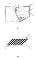
- a device comprising firstly a moire grid 1 fixed on a support 2 and an image acquisition means 8 provided with an objective are recognized in schematic view from above.
- the support 2 is a housing, opaque preference to avoid light pollution.
- the moire grid 1 slides along the walls of the housing to a maximum position so that it does not move once positioned on the support 2.
- the moire grid can be fixed on the support 2 by screwing.
- a light source for example a diode
- This axis 4 has an incidence of, for example, between 40 ° and 50 °, preferably 45 °, on the plan of the moire grid 1.
- the support 2 may have a location 6 to make the device autonomous, this location 6 may for example contain an electric battery 5. This location 6 is then preferably delimited by a separator to prevent the light coming directly from the diode to reach the objective of the image acquisition means and thus not to disturb the intensity measurements during the phase calculations explained below.
- the acquisition means of the image 8 is fixed on an opening 7 whose support 2 is provided.
- This means is schematically represented here.
- This is for example a digital camera.
- this digital camera is mounted with a screw thread 9 (but of course any other means of attachment could be used here).
- the opening 7 and the screw thread 9 allow the digital camera to photograph the moiré grid 1 along an observation axis 10.
- the characteristics of the assembly ie the observation and illumination axes 4, are reproducible very easily, without the risk of obtaining different information for the same damage. that would entail a change of these.
- the angle between these two axes 4 and 10 is 45 °.
- This moire grid firstly comprises a transparent support 11.
- this grid has a grid pitch defined by the alternation on the upper face of this transparent support 11 with transparent bands 12 and dark bands 13.
- the dark bands 13 may for example be screen printed on the surface superior of the transparent support 11. Necessarily, the thickness of this support is not zero. This observation makes it possible to understand that by keeping the plane of the grid above the plane of support of the support on the surface to be analyzed, this characteristic makes it possible to observe fringes without raising the device, even when no damage is observed. present. Still concerning the grid, one can also treat the upper surface of the grid to minimize reflections. The contrast of the observed pattern is then increased.
- the grid 1 is oriented so that its longitudinal strips 12, 13 do not form a zero angle with the alignment between the image acquisition means 8 and the light source. 3, that is to say the plane containing the lighting axes 4 and 10 observation.
- the longitudinal strips 12 and 13 will be perpendicular to this plane to observe the fringes more contrasted.
- the parameters of the image acquisition means Before traversing the surface, the parameters of the image acquisition means must be adjusted properly to obtain optimum results. Contrary to what one might think, a good adjustment of the means of acquisition of the image does not necessarily correspond to a maximum setting of the resolution. For example, for a defect of the order of a millimeter, a lesser resolution will suffice to characterize the damage with respect to the resolution necessary to characterize defects of the order of 10 microns. The analysis will also be faster with less resolution. These settings depend on the device used and the structures tested and are usually determined by testing.
- the figure 4 gives an example of the image of the pattern of the moire fringes that the image acquisition means 8 can record during the passage on a surface damage.
- This figure shows dark fringes of low intensity 15 and clear fringes of higher intensity 16. These dark fringes 15 and clear 16 are no longer parallel as they are when no damage is present. In this figure, they form in particular concentric patterns around the center of the damage 17.
- the image is then analyzed by processing means that will apply algorithms to obtain a representation of the damage observed from the pattern of moiré fringes.
- ⁇ x ⁇ there 2 ⁇ ⁇ p ⁇ tan ⁇ + tan ⁇ ⁇ z , where p corresponds to the pitch of the grid, ⁇ and ⁇ correspond to the illumination and observation angles, and z to the height relative to a reference plane.
- phase demodulation ⁇ (x, y) can be obtained from intensity I (x, y).
- the fields ⁇ x (x, y) and ⁇ y (x, y) are estimates of local frequencies along the x and y axes . These fields also represent the slopes of the phase plane. Finally, the parameter ⁇ is a constant that controls the regularity of the phase ⁇ 0 ( x, y ).
- phase demodulation it is necessary to minimize the cost function U (x, y) for each point as a function of the variables ⁇ 0 ( x, y ), ⁇ x ( x, y ) and ⁇ y ( x, y ).
- this function is not linear. So we can not use fast optimization techniques.
- ⁇ r denotes the gradient of U ( x, y ) as a function of the three components of r.
- This method requires an initial condition r 0 .
- the regularity constant ⁇ is not taken into account since the starting point is the first to undergo demodulation and therefore the indicator function m (x , y ) is equal to 0 on S.
- the root vector r ( x 0 , y 0 ) has been calculated, it is possible to continue with the rest of the points on S. This algorithm must follow a sequential and continuous trajectory, point by point, from the root point.
- this algorithm sequentially demodulates the pattern drawn by the moiré fringes, starting from a starting point and then propagating until the whole of the area to be moire. analyze has been covered.
- the way of traversing the pattern is a critical phase of demodulation.
- the goal when navigating the moiré fringe pattern is to guide the algorithm so that higher quality areas are prioritized and areas of lower quality last.
- This technique has the effect of limiting possible errors to only areas where the quality is lower.
- the amplitude parameter b ( x , y ) In the case of phase shift, it is easy to obtain the modulation of this parameter.
- the modulation is generally more difficult to obtain.
- the technique used by the algorithm of the invention is to follow the pattern of the fringes of the pattern, ie to go through the pattern along the isophase lines.
- This strategy has been described by Servin and Quiroga in their publication "Isochromatics demodulation from a single image using a regularized phase tracking technique" ( M. servin, JA Quiroga, Journal of Modern Optics, Volume 48, Number 3, 521-531, 2001 ).
- the principle is to assign a level of "quality" for a gray level of the image. For example, in a 256-grayscale image, one can arbitrarily choose that the "best-quality" areas correspond to grayscale levels greater than 128, and "low-quality” areas to levels lower than 128. using this principle, the image is divided into two areas.
- Demodulation will then take priority over the "best quality” zones and then the "low quality” zones, which means that the quality as defined by this technique does not correspond to a signal-to-quality ratio. high noise. From the intensity of the fringe patterns, it is therefore possible to build a two-level quality map and demodulate, in priority, the "best quality” zones to which, for example, a value of 1 and the zones of "low quality” can be assigned. "a value of 0.
- the phase modulation is obtained differently.
- the first term not ⁇ r ⁇ ⁇ r ⁇ ⁇ r is a unitary vector normal to the corresponding isophases, directed in the direction of the orientation term of the fringes ⁇ ( r ).
- This term related to the direction of the fringes can not be calculated directly because we access the phase only through the intensity, and the orientation angles of the fringes calculated by the intensity gradient do not correspond not at the angles calculated by the phase gradient. It is necessary to develop the phase to obtain the term of orientation of the fringes.
- modulation and background variations are undesirable because the cost function compares the measured values with the pattern of the fringe pattern: no background and constant sine modulation. It is therefore necessary to previously process images of the pattern of the fringes to eliminate the background and normalize the modulation.
- the orientation field can not be obtained directly from the phase gradient.
- the use of the first or second embodiment depends on the user of the system.
- the second mode is faster and is generally sufficient to represent the deformation corresponding to the pattern.
- the first mode is more robust and is used when the results of the second mode are inconclusive.
- the user After having selected the algorithm to be used and the analysis of the pattern carried out, the user must specify to the system a point of the image corresponding to a zero height, which makes it possible to obtain a complete representation of the deformation represented on the image. image by the pattern of the fringes.
- the algorithms determine the height z of the surface corresponding to this position.
- FIG. 5 there is shown a two-dimensional view of a damage 18 obtained by the algorithms presented above.
- Scales 19, 20 of dimensions of the order of ten micrometers allow the user to characterize the damage represented as a function of the different spatial positions of the surface 18 in terms of width and depth, in a given direction.
- This type of two-dimensional view corresponds to a section of the damage.
- FIG. 6 there is shown a three-dimensional view of the damage 21 obtained using the algorithms presented above.
- Scales 22, 23, 24 whose unit is ten micrometers, can accurately represent the damage 21.
- To characterize the damage can then be used various criteria. The characterization criteria depend on the application, but from the complete geometry, the person skilled in the art can determine, for example, whether certain predetermined maximum limits in one of the directions have been reached.
- the representation of Figures 5 and 6 can also be a color representation.
- a color scale can then be defined. It can for example be representative of the depth of the damage, the point of the deepest damage may for example be represented by a dark color while the rest of the damage could be colored degraded from zero height from the surface where the color would be lighter.
- the color graphic representation can be a two or more dimensional view of the damage.
Landscapes
- Physics & Mathematics (AREA)
- General Physics & Mathematics (AREA)
- Biochemistry (AREA)
- Pathology (AREA)
- Health & Medical Sciences (AREA)
- Life Sciences & Earth Sciences (AREA)
- Chemical & Material Sciences (AREA)
- Analytical Chemistry (AREA)
- Engineering & Computer Science (AREA)
- General Health & Medical Sciences (AREA)
- Immunology (AREA)
- Computer Vision & Pattern Recognition (AREA)
- Length Measuring Devices By Optical Means (AREA)
- Facsimile Scanning Arrangements (AREA)
- Facsimile Image Signal Circuits (AREA)
- Credit Cards Or The Like (AREA)
- Image Processing (AREA)
- Analysing Materials By The Use Of Radiation (AREA)
- Character Input (AREA)
Claims (14)
- Verfahren zur Kennzeichnung eines Strukturschadens, umfassend die Schritte: ein Moire-Gitter (1) in Nähe der Oberfläche (14) der Struktur anordnen, eine Lichtquelle (3) auf das Gitter (1) so richten, dass ein Schatten des Gitters auf der Struktur erzeugt wird, und mit Hilfe eines Erfassungsmittels (8) ein Bild des Musters aufzeichnen, das durch das Gitter hindurch in einer von der Richtung der Lichtquelle abweichenden Beobachtungsrichtung beobachtet wird, wobei das Gitter (1) ein flexibles Gitter ist, das direkt auf die zu analysierende Oberfläche (14) aufgelegt ist, wobei dieses Verfahren außerdem die folgenden Schritte umfasst:- den Schaden ausgehend von dem aufgezeichneten Bild mit Hilfe eines Algorithmus zur Behandlung des Bildes graphisch darstellen und- den Schaden ausgehend von dieser Darstellung kennzeichnen.
- Verfahren nach Anspruch 1, dadurch gekennzeichnet, dass es au-ßerdem die Schritte umfasst: die Oberfläche durchgehen, visuell das Vorhandensein oder nicht von Verformungen des Musters kontrollieren, das Durchgehen der Oberfläche anhalten, das Bild mit Hilfe eines Erfassungsmittels aufzeichnen und den Schaden kennzeichnen.
- Verfahren nach Anspruch 2, umfassend die Schritte: ein oder mehrere aufgezeichnete, nicht behandelte Bilder zu versetzten Behandlungsmitteln übertragen, um die Schäden in verzögerter Zeit zu kennzeichnen.
- Verfahren nach Anspruch 3, dadurch gekennzeichnet, dass der Algorithmus zur Behandlung des Bilds einen Schritt der Normalisierung der auf dem Bild erscheinenden Interferenzstreifen umfasst.
- Verfahren nach Anspruch 3, dadurch gekennzeichnet, dass der Algorithmus die Phasenmodulierung ausführt, um die räumliche Lage jedes Punkts des Bilds ausgehend von den Merkmalen der Montage und von der beobachteten Stärke zu bestimmen.
- Verfahren nach einem der vorhergehenden Ansprüche, dadurch gekennzeichnet, dass das Ergebnis des Schritts der graphischen Darstellung des Schadens eine graphische Darstellung nach einer Farbskala ist.
- Verfahren nach einem der vorhergehenden Ansprüche, dadurch gekennzeichnet, dass das Ergebnis der Behandlungsmittel eine zweidimensionale graphische Darstellung des Schadens (18) ist.
- Verfahren nach einem der vorhergehenden Ansprüche, dadurch gekennzeichnet, dass das Ergebnis der Behandlungsmittel in eine graphische Darstellung des Schadens (21) in mehreren Dimensionen umgewandelt wird.
- Vorrichtung zur Kennzeichnung eines Strukturschadens, umfassend:- einen Halter (2),- ein Moire-Gitter (1),- ein Beleuchtungsmittel (3),- ein Bilderfassungsmittel (8), dessen Beobachtungsachse (10) gegen diejenige des Beleuchtungsmittels (4) versetzt ist,- ein Bildbehandlungsmittel,- ein Mittel zur Anzeige des Ergebnisses dieser Behandlung,dadurch gekennzeichnet, dass das Moire-Gitter (1) flexibel ist.
- Vorrichtung nach Anspruch 9, dadurch gekennzeichnet, dass das Moire-Gitter (1) vor seiner Verwendung einer Antireflexbehandlung unterzogen wird.
- Vorrichtung nach einem der Ansprüche 9 oder 10, dadurch gekennzeichnet, dass das Bilderfassungsmittel (8) an dem Halter befestigt ist.
- Vorrichtung nach einem der Ansprüche 9 bis 11, dadurch gekennzeichnet, dass eine Aufzeichnung des Bilds durch ein digitales Erfassungsmittel stattfindet.
- Vorrichtung nach Anspruch 12, dadurch gekennzeichnet, dass die Aufzeichnung durch Behandlungsmittel behandelt wird, die Bildbehandlungsalgorithmen anlegen.
- Vorrichtung nach einem der Ansprüche 9 bis 13, dadurch gekennzeichnet, dass sie außerdem Mittel umfasst, um das von dem Bildbehandlungsmittel gelieferte Ergebnis graphisch umzuwandeln, einen Bildschirm für die Visualisierung der erhaltenen graphischen Darstellung, die eine Darstellung in einer Farbskala durch Aufnahmen in zwei oder drei Dimensionen (18, 21) gestatten.
Applications Claiming Priority (2)
| Application Number | Priority Date | Filing Date | Title |
|---|---|---|---|
| FR0403096A FR2868156B1 (fr) | 2004-03-25 | 2004-03-25 | Procede et dispositif de controle non destructif de structure et de caracterisation des endommagements de structure par le principe de moire d'ombre |
| FR0403096 | 2004-03-25 |
Publications (3)
| Publication Number | Publication Date |
|---|---|
| EP1580524A2 EP1580524A2 (de) | 2005-09-28 |
| EP1580524A3 EP1580524A3 (de) | 2006-06-07 |
| EP1580524B1 true EP1580524B1 (de) | 2008-08-20 |
Family
ID=34855162
Family Applications (1)
| Application Number | Title | Priority Date | Filing Date |
|---|---|---|---|
| EP05290646A Expired - Lifetime EP1580524B1 (de) | 2004-03-25 | 2005-03-24 | Verfahren und Vorrichtung zur Charakterisierung von Strukturschäden mittels Moiré- Schatten |
Country Status (5)
| Country | Link |
|---|---|
| US (1) | US7298499B2 (de) |
| EP (1) | EP1580524B1 (de) |
| AT (1) | ATE405812T1 (de) |
| DE (1) | DE602005009053D1 (de) |
| FR (1) | FR2868156B1 (de) |
Families Citing this family (21)
| Publication number | Priority date | Publication date | Assignee | Title |
|---|---|---|---|---|
| US7595894B2 (en) * | 2006-06-02 | 2009-09-29 | General Electric Company | Profilometry apparatus and method of operation |
| US10157495B2 (en) * | 2011-03-04 | 2018-12-18 | General Electric Company | Method and device for displaying a two-dimensional image of a viewed object simultaneously with an image depicting the three-dimensional geometry of the viewed object |
| US10586341B2 (en) | 2011-03-04 | 2020-03-10 | General Electric Company | Method and device for measuring features on or near an object |
| US9875574B2 (en) * | 2013-12-17 | 2018-01-23 | General Electric Company | Method and device for automatically identifying the deepest point on the surface of an anomaly |
| US10580075B1 (en) | 2012-08-16 | 2020-03-03 | Allstate Insurance Company | Application facilitated claims damage estimation |
| US12175540B2 (en) | 2012-08-16 | 2024-12-24 | Allstate Insurance Company | Processing insured items holistically with mobile damage assessment and claims processing |
| US10783585B1 (en) | 2012-08-16 | 2020-09-22 | Allstate Insurance Company | Agent-facilitated claims damage estimation |
| US11455691B2 (en) | 2012-08-16 | 2022-09-27 | Allstate Insurance Company | Processing insured items holistically with mobile damage assessment and claims processing |
| US20220036463A1 (en) | 2012-08-16 | 2022-02-03 | Allstate Insurance Company | User devices in claims damage estimation |
| US8712893B1 (en) | 2012-08-16 | 2014-04-29 | Allstate Insurance Company | Enhanced claims damage estimation using aggregate display |
| US10430885B1 (en) | 2012-08-16 | 2019-10-01 | Allstate Insurance Company | Processing insured items holistically with mobile damage assessment and claims processing |
| US10572944B1 (en) | 2012-08-16 | 2020-02-25 | Allstate Insurance Company | Claims damage estimation using enhanced display |
| US11532048B2 (en) | 2012-08-16 | 2022-12-20 | Allstate Insurance Company | User interactions in mobile damage assessment and claims processing |
| US8510196B1 (en) | 2012-08-16 | 2013-08-13 | Allstate Insurance Company | Feedback loop in mobile damage assessment and claims processing |
| FR3001564B1 (fr) * | 2013-01-31 | 2016-05-27 | Vit | Systeme de determination d'une image tridimensionnelle d'un circuit electronique |
| US9818039B2 (en) * | 2013-12-17 | 2017-11-14 | General Electric Company | Method and device for automatically identifying a point of interest in a depth measurement on a viewed object |
| US9250066B2 (en) * | 2014-03-21 | 2016-02-02 | Charles Thorndike | System for measuring base edge bevel angles and conditions of base flatness for skis and snowboards |
| US9824453B1 (en) | 2015-10-14 | 2017-11-21 | Allstate Insurance Company | Three dimensional image scan for vehicle |
| FR3045828B1 (fr) * | 2015-12-17 | 2019-04-05 | Airbus Group Sas | Dispositif de mesure et de controle de conformite d'un impact sur une structure |
| CN111156931A (zh) * | 2020-02-25 | 2020-05-15 | 成都威博恩科技有限公司 | 一种高精度平面度检测装置及方法 |
| CN115452820B (zh) * | 2022-07-21 | 2023-10-27 | 成都华建地质工程科技有限公司 | 基于钻孔电视图像提取结构面特征的方法及装置和介质 |
Family Cites Families (5)
| Publication number | Priority date | Publication date | Assignee | Title |
|---|---|---|---|---|
| US5025285A (en) * | 1989-05-10 | 1991-06-18 | Grumman Aerospace Corporation | Apparatus and method for shadow moire mapping |
| US5311286A (en) * | 1992-04-01 | 1994-05-10 | Materials Technologies Corporation | Apparatus and method for optically measuring a surface |
| GB9405457D0 (en) * | 1994-03-19 | 1994-05-04 | British Aerospace | Testing a metal component for cold compression of the metal |
| US6731391B1 (en) * | 1998-05-13 | 2004-05-04 | The Research Foundation Of State University Of New York | Shadow moire surface measurement using Talbot effect |
| GB9828474D0 (en) | 1998-12-24 | 1999-02-17 | British Aerospace | Surface topology inspection |
-
2004
- 2004-03-25 FR FR0403096A patent/FR2868156B1/fr not_active Expired - Fee Related
-
2005
- 2005-03-24 EP EP05290646A patent/EP1580524B1/de not_active Expired - Lifetime
- 2005-03-24 AT AT05290646T patent/ATE405812T1/de not_active IP Right Cessation
- 2005-03-24 DE DE602005009053T patent/DE602005009053D1/de not_active Expired - Lifetime
- 2005-03-25 US US11/088,787 patent/US7298499B2/en not_active Expired - Lifetime
Also Published As
| Publication number | Publication date |
|---|---|
| ATE405812T1 (de) | 2008-09-15 |
| EP1580524A2 (de) | 2005-09-28 |
| EP1580524A3 (de) | 2006-06-07 |
| US7298499B2 (en) | 2007-11-20 |
| FR2868156B1 (fr) | 2006-11-10 |
| DE602005009053D1 (de) | 2008-10-02 |
| FR2868156A1 (fr) | 2005-09-30 |
| US20050246108A1 (en) | 2005-11-03 |
Similar Documents
| Publication | Publication Date | Title |
|---|---|---|
| EP1580524B1 (de) | Verfahren und Vorrichtung zur Charakterisierung von Strukturschäden mittels Moiré- Schatten | |
| EP2553439B1 (de) | Verfahren und vorrichtung zur analyse der optischen qualität eines durchsichtigen substrats | |
| FR2951543A1 (fr) | Procede d'analyse de la qualite d'un vitrage | |
| EP1605241A1 (de) | Apparat zur optischen Kontrolle von transparenten oder reflektierenden Proben | |
| WO2000042401A2 (fr) | Procede et dispositif d'analyse d'un front d'onde a grande dynamique | |
| EP3388976A1 (de) | Betrugserkennungsverfahren | |
| EP0756152B1 (de) | Verfahren und Vorrichtung zur Detektierung des Zustandes der Oberfläche eines Objektes mit einer reflektierenden Oberfläche, anwendbar zur Kontrolle der Rauhigkeit von polierten Objekten | |
| WO2004083772A2 (fr) | Procede de mesure d'objets tridimensionnels par ombroscopie optique a une seule vue | |
| FR2632728A1 (fr) | Procede et appareil pour la determination automatique du comportement d'une goutte d'un liquide par rapport a une surface d'un materiau | |
| FR3071611A1 (fr) | Procede et dispositif de controle non destructif d'une piece aeronautique | |
| EP4246135B1 (de) | Verbessertes verfahren zur messung der ausrichtung eines zeilenablenkungsfehlers in kleinen winkeln durch t-saxs-übertragung ; entsprechendes instrumentalsystem und computerprogrammprodukt | |
| EP4451060B1 (de) | Verfahren zur identifizierung eines fehlers, der ein von einer mikroelektronischen komponente getragenes kontrollmuster beeinflusst, steuerverfahren, entsprechendes instrument und computerprogrammprodukt | |
| EP2029399B1 (de) | Verfahren zur analyse einer integrierten schaltung, beobachtungsverfahren und entsprechende installationen | |
| WO2018060359A1 (fr) | Procede et dispositif d'analyse d'une onde electromagnetique en haute definition | |
| EP3080592A1 (de) | Verfahren und vorrichtung zur analyse der oberfläche eines substrats | |
| FR2836575A1 (fr) | Procede de mesure de la localisation d'un objet par detection de phase | |
| WO2012143649A1 (fr) | Procede d'analyse de la qualite d'un vitrage | |
| EP3617646B1 (de) | Messmethode der linienrauheit eines liniennetzes durch beugung von röntgenstrahlen | |
| EP4118616B1 (de) | Verfahren und system zur zerstörungsfreien prüfung einer aeronautischen komponente | |
| EP2366986B1 (de) | Metrologieverfahren zur Messung optischer Gangunterschiede in einem statischen Interferometer | |
| FR2921492A1 (fr) | Procede de positionnement cartesien d'un objet sur une surface et dispositif pour sa mise en oeuvre | |
| EP4565844A1 (de) | Verbessertes deflektometrieverfahren und zugehöriges system | |
| FR3144289A1 (fr) | Procédé amélioré de mesure mettant en œuvre une technique par diffusion des rayons X aux petits angles en incidence rasante – GISAXS ; Système instrumental et produit programme d’ordinateur associés. | |
| FR3051551A1 (fr) | Appareil et procede de mesure d'un etat de surface ou de volume d'un objet par diffusion en champ lointain | |
| WO2007077312A2 (fr) | Procede et dispositif d'observation d'un objet. |
Legal Events
| Date | Code | Title | Description |
|---|---|---|---|
| PUAI | Public reference made under article 153(3) epc to a published international application that has entered the european phase |
Free format text: ORIGINAL CODE: 0009012 |
|
| AK | Designated contracting states |
Kind code of ref document: A2 Designated state(s): AT BE BG CH CY CZ DE DK EE ES FI FR GB GR HU IE IS IT LI LT LU MC NL PL PT RO SE SI SK TR |
|
| AX | Request for extension of the european patent |
Extension state: AL BA HR LV MK YU |
|
| PUAL | Search report despatched |
Free format text: ORIGINAL CODE: 0009013 |
|
| AK | Designated contracting states |
Kind code of ref document: A3 Designated state(s): AT BE BG CH CY CZ DE DK EE ES FI FR GB GR HU IE IS IT LI LT LU MC NL PL PT RO SE SI SK TR |
|
| AX | Request for extension of the european patent |
Extension state: AL BA HR LV MK YU |
|
| RIC1 | Information provided on ipc code assigned before grant |
Ipc: G01B 11/25 20060101AFI20050722BHEP Ipc: G01B 11/16 20060101ALI20060503BHEP Ipc: G01B 11/30 20060101ALI20060503BHEP |
|
| 17P | Request for examination filed |
Effective date: 20061028 |
|
| 17Q | First examination report despatched |
Effective date: 20061219 |
|
| AKX | Designation fees paid |
Designated state(s): AT BE BG CH CY CZ DE DK EE ES FI FR GB GR HU IE IS IT LI LT LU MC NL PL PT RO SE SI SK TR |
|
| GRAP | Despatch of communication of intention to grant a patent |
Free format text: ORIGINAL CODE: EPIDOSNIGR1 |
|
| GRAS | Grant fee paid |
Free format text: ORIGINAL CODE: EPIDOSNIGR3 |
|
| GRAA | (expected) grant |
Free format text: ORIGINAL CODE: 0009210 |
|
| AK | Designated contracting states |
Kind code of ref document: B1 Designated state(s): AT BE BG CH CY CZ DE DK EE ES FI FR GB GR HU IE IS IT LI LT LU MC NL PL PT RO SE SI SK TR |
|
| REG | Reference to a national code |
Ref country code: GB Ref legal event code: FG4D Free format text: NOT ENGLISH |
|
| REG | Reference to a national code |
Ref country code: CH Ref legal event code: EP |
|
| REG | Reference to a national code |
Ref country code: IE Ref legal event code: FG4D Free format text: LANGUAGE OF EP DOCUMENT: FRENCH |
|
| REF | Corresponds to: |
Ref document number: 602005009053 Country of ref document: DE Date of ref document: 20081002 Kind code of ref document: P |
|
| REG | Reference to a national code |
Ref country code: SE Ref legal event code: TRGR |
|
| PG25 | Lapsed in a contracting state [announced via postgrant information from national office to epo] |
Ref country code: LT Free format text: LAPSE BECAUSE OF FAILURE TO SUBMIT A TRANSLATION OF THE DESCRIPTION OR TO PAY THE FEE WITHIN THE PRESCRIBED TIME-LIMIT Effective date: 20080820 Ref country code: NL Free format text: LAPSE BECAUSE OF FAILURE TO SUBMIT A TRANSLATION OF THE DESCRIPTION OR TO PAY THE FEE WITHIN THE PRESCRIBED TIME-LIMIT Effective date: 20080820 Ref country code: IS Free format text: LAPSE BECAUSE OF FAILURE TO SUBMIT A TRANSLATION OF THE DESCRIPTION OR TO PAY THE FEE WITHIN THE PRESCRIBED TIME-LIMIT Effective date: 20081220 |
|
| PG25 | Lapsed in a contracting state [announced via postgrant information from national office to epo] |
Ref country code: ES Free format text: LAPSE BECAUSE OF FAILURE TO SUBMIT A TRANSLATION OF THE DESCRIPTION OR TO PAY THE FEE WITHIN THE PRESCRIBED TIME-LIMIT Effective date: 20081201 Ref country code: FI Free format text: LAPSE BECAUSE OF FAILURE TO SUBMIT A TRANSLATION OF THE DESCRIPTION OR TO PAY THE FEE WITHIN THE PRESCRIBED TIME-LIMIT Effective date: 20080820 Ref country code: AT Free format text: LAPSE BECAUSE OF FAILURE TO SUBMIT A TRANSLATION OF THE DESCRIPTION OR TO PAY THE FEE WITHIN THE PRESCRIBED TIME-LIMIT Effective date: 20080820 Ref country code: SI Free format text: LAPSE BECAUSE OF FAILURE TO SUBMIT A TRANSLATION OF THE DESCRIPTION OR TO PAY THE FEE WITHIN THE PRESCRIBED TIME-LIMIT Effective date: 20080820 |
|
| REG | Reference to a national code |
Ref country code: IE Ref legal event code: FD4D |
|
| PG25 | Lapsed in a contracting state [announced via postgrant information from national office to epo] |
Ref country code: IE Free format text: LAPSE BECAUSE OF FAILURE TO SUBMIT A TRANSLATION OF THE DESCRIPTION OR TO PAY THE FEE WITHIN THE PRESCRIBED TIME-LIMIT Effective date: 20080820 Ref country code: BG Free format text: LAPSE BECAUSE OF FAILURE TO SUBMIT A TRANSLATION OF THE DESCRIPTION OR TO PAY THE FEE WITHIN THE PRESCRIBED TIME-LIMIT Effective date: 20081120 Ref country code: DK Free format text: LAPSE BECAUSE OF FAILURE TO SUBMIT A TRANSLATION OF THE DESCRIPTION OR TO PAY THE FEE WITHIN THE PRESCRIBED TIME-LIMIT Effective date: 20080820 |
|
| PG25 | Lapsed in a contracting state [announced via postgrant information from national office to epo] |
Ref country code: SK Free format text: LAPSE BECAUSE OF FAILURE TO SUBMIT A TRANSLATION OF THE DESCRIPTION OR TO PAY THE FEE WITHIN THE PRESCRIBED TIME-LIMIT Effective date: 20080820 Ref country code: RO Free format text: LAPSE BECAUSE OF FAILURE TO SUBMIT A TRANSLATION OF THE DESCRIPTION OR TO PAY THE FEE WITHIN THE PRESCRIBED TIME-LIMIT Effective date: 20080820 Ref country code: PT Free format text: LAPSE BECAUSE OF FAILURE TO SUBMIT A TRANSLATION OF THE DESCRIPTION OR TO PAY THE FEE WITHIN THE PRESCRIBED TIME-LIMIT Effective date: 20090120 Ref country code: CZ Free format text: LAPSE BECAUSE OF FAILURE TO SUBMIT A TRANSLATION OF THE DESCRIPTION OR TO PAY THE FEE WITHIN THE PRESCRIBED TIME-LIMIT Effective date: 20080820 |
|
| PLBE | No opposition filed within time limit |
Free format text: ORIGINAL CODE: 0009261 |
|
| STAA | Information on the status of an ep patent application or granted ep patent |
Free format text: STATUS: NO OPPOSITION FILED WITHIN TIME LIMIT |
|
| 26N | No opposition filed |
Effective date: 20090525 |
|
| PG25 | Lapsed in a contracting state [announced via postgrant information from national office to epo] |
Ref country code: EE Free format text: LAPSE BECAUSE OF FAILURE TO SUBMIT A TRANSLATION OF THE DESCRIPTION OR TO PAY THE FEE WITHIN THE PRESCRIBED TIME-LIMIT Effective date: 20080820 |
|
| BERE | Be: lapsed |
Owner name: AIRBUS FRANCE Effective date: 20090331 |
|
| PG25 | Lapsed in a contracting state [announced via postgrant information from national office to epo] |
Ref country code: MC Free format text: LAPSE BECAUSE OF NON-PAYMENT OF DUE FEES Effective date: 20090331 |
|
| REG | Reference to a national code |
Ref country code: CH Ref legal event code: PL |
|
| PG25 | Lapsed in a contracting state [announced via postgrant information from national office to epo] |
Ref country code: LI Free format text: LAPSE BECAUSE OF NON-PAYMENT OF DUE FEES Effective date: 20090331 Ref country code: CH Free format text: LAPSE BECAUSE OF NON-PAYMENT OF DUE FEES Effective date: 20090331 |
|
| PG25 | Lapsed in a contracting state [announced via postgrant information from national office to epo] |
Ref country code: BE Free format text: LAPSE BECAUSE OF NON-PAYMENT OF DUE FEES Effective date: 20090331 |
|
| PG25 | Lapsed in a contracting state [announced via postgrant information from national office to epo] |
Ref country code: PL Free format text: LAPSE BECAUSE OF FAILURE TO SUBMIT A TRANSLATION OF THE DESCRIPTION OR TO PAY THE FEE WITHIN THE PRESCRIBED TIME-LIMIT Effective date: 20080820 |
|
| PG25 | Lapsed in a contracting state [announced via postgrant information from national office to epo] |
Ref country code: GR Free format text: LAPSE BECAUSE OF FAILURE TO SUBMIT A TRANSLATION OF THE DESCRIPTION OR TO PAY THE FEE WITHIN THE PRESCRIBED TIME-LIMIT Effective date: 20081121 |
|
| PG25 | Lapsed in a contracting state [announced via postgrant information from national office to epo] |
Ref country code: LU Free format text: LAPSE BECAUSE OF NON-PAYMENT OF DUE FEES Effective date: 20090324 |
|
| PG25 | Lapsed in a contracting state [announced via postgrant information from national office to epo] |
Ref country code: HU Free format text: LAPSE BECAUSE OF FAILURE TO SUBMIT A TRANSLATION OF THE DESCRIPTION OR TO PAY THE FEE WITHIN THE PRESCRIBED TIME-LIMIT Effective date: 20090221 |
|
| REG | Reference to a national code |
Ref country code: GB Ref legal event code: 732E Free format text: REGISTERED BETWEEN 20110721 AND 20110727 |
|
| PG25 | Lapsed in a contracting state [announced via postgrant information from national office to epo] |
Ref country code: TR Free format text: LAPSE BECAUSE OF FAILURE TO SUBMIT A TRANSLATION OF THE DESCRIPTION OR TO PAY THE FEE WITHIN THE PRESCRIBED TIME-LIMIT Effective date: 20080820 |
|
| PG25 | Lapsed in a contracting state [announced via postgrant information from national office to epo] |
Ref country code: CY Free format text: LAPSE BECAUSE OF FAILURE TO SUBMIT A TRANSLATION OF THE DESCRIPTION OR TO PAY THE FEE WITHIN THE PRESCRIBED TIME-LIMIT Effective date: 20080820 |
|
| REG | Reference to a national code |
Ref country code: DE Ref legal event code: R082 Ref document number: 602005009053 Country of ref document: DE Representative=s name: MANITZ, FINSTERWALD & PARTNER GBR, DE |
|
| REG | Reference to a national code |
Ref country code: DE Ref legal event code: R082 Ref document number: 602005009053 Country of ref document: DE Representative=s name: MANITZ, FINSTERWALD & PARTNER GBR, DE Effective date: 20120326 Ref country code: DE Ref legal event code: R081 Ref document number: 602005009053 Country of ref document: DE Owner name: AIRBUS OPERATIONS SAS, FR Free format text: FORMER OWNER: AIRBUS FRANCE, TOULOUSE, FR Effective date: 20120326 Ref country code: DE Ref legal event code: R082 Ref document number: 602005009053 Country of ref document: DE Representative=s name: MANITZ FINSTERWALD PATENTANWAELTE PARTMBB, DE Effective date: 20120326 |
|
| PGFP | Annual fee paid to national office [announced via postgrant information from national office to epo] |
Ref country code: IT Payment date: 20120327 Year of fee payment: 8 Ref country code: SE Payment date: 20120322 Year of fee payment: 8 |
|
| REG | Reference to a national code |
Ref country code: SE Ref legal event code: EUG |
|
| PG25 | Lapsed in a contracting state [announced via postgrant information from national office to epo] |
Ref country code: SE Free format text: LAPSE BECAUSE OF NON-PAYMENT OF DUE FEES Effective date: 20130325 |
|
| PG25 | Lapsed in a contracting state [announced via postgrant information from national office to epo] |
Ref country code: IT Free format text: LAPSE BECAUSE OF NON-PAYMENT OF DUE FEES Effective date: 20130324 |
|
| REG | Reference to a national code |
Ref country code: FR Ref legal event code: PLFP Year of fee payment: 12 |
|
| REG | Reference to a national code |
Ref country code: FR Ref legal event code: PLFP Year of fee payment: 13 |
|
| REG | Reference to a national code |
Ref country code: FR Ref legal event code: PLFP Year of fee payment: 14 |
|
| PGFP | Annual fee paid to national office [announced via postgrant information from national office to epo] |
Ref country code: DE Payment date: 20220322 Year of fee payment: 18 |
|
| REG | Reference to a national code |
Ref country code: DE Ref legal event code: R119 Ref document number: 602005009053 Country of ref document: DE |
|
| PG25 | Lapsed in a contracting state [announced via postgrant information from national office to epo] |
Ref country code: DE Free format text: LAPSE BECAUSE OF NON-PAYMENT OF DUE FEES Effective date: 20231003 |
|
| PGFP | Annual fee paid to national office [announced via postgrant information from national office to epo] |
Ref country code: GB Payment date: 20240320 Year of fee payment: 20 |
|
| PGFP | Annual fee paid to national office [announced via postgrant information from national office to epo] |
Ref country code: FR Payment date: 20240321 Year of fee payment: 20 |
|
| REG | Reference to a national code |
Ref country code: GB Ref legal event code: PE20 Expiry date: 20250323 |
|
| PG25 | Lapsed in a contracting state [announced via postgrant information from national office to epo] |
Ref country code: GB Free format text: LAPSE BECAUSE OF EXPIRATION OF PROTECTION Effective date: 20250323 |